Sign In
Upload
Manuals
Brands
Anritsu Manuals
Portable Generator
681 B Series
Anritsu 681 B Series Manuals
Manuals and User Guides for Anritsu 681 B Series. We have
1
Anritsu 681 B Series manual available for free PDF download: Maintenance Manual
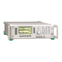
Anritsu 681 B Series Maintenance Manual (438 pages)
SYNTHESIZED CW/SWEEP GENERATORS
Brand:
Anritsu
| Category:
Portable Generator
| Size: 3 MB
Table of Contents
Table of Contents
5
Description
13
Introduction
13
Scope of Manual
13
Electronic Manual
16
GPIB Programming Manual
16
Identification Number
16
Operation Manual
16
Related Manuals
16
SCPI Programming Manual
16
Options
17
Calibration
18
Level of Maintenance
18
Preventive Maintenance
18
Repair
18
Troubleshooting
18
Static-Sensitive Component Handling Precautions
20
Startup Configurations
21
Recommended Test Equipment
22
Exchange Assembly Program
24
Replaceable Subassemblies and Parts
25
680Xxb/681Xxb Major Subsystems
33
Introduction
33
Digital Control
34
Frequency Synthesis
34
Front Panel
34
Analog Instruction
35
Alc/Modulation
40
RF Deck
40
YIG Driver
40
Inputs/Outputs
41
Power Supply
41
Frequency Synthesis
42
Motherboard/Interconnections
42
Phase Lock Loops
42
Overall Operation
45
RF Outputs 0.01 to 65 Ghz
47
Analog Sweep Mode (681XXB Only)
48
Frequency Modulation (681XXB Only)
48
Step Sweep Mode
48
Alc and Modulation
49
ALC Loop Operation
49
Amplitude Modulation (681XXB Only)
50
Square Wave Modulation (681XXB Only)
53
Power Level Control and Modulation
57
Rf Deck Assemblies
57
YIG-Tuned Oscillator
57
RF Signal Filtering
58
To 2 Ghz down Converter
59
To 2.2 Ghz Digital down Converter
59
Switched Doubler Module
60
Source Quadrupler Module
63
Power Level Detection/Alc Loop
65
Step Attenuator
65
Connector and Key Label Notation
69
Introduction
69
Recommended Test Equipment
69
Test Records
69
680Xxb/681Xxb Power Levels
72
Internal Time Base Aging Rate Test
74
Test Setup
74
Test Procedure
75
Frequency Synthesis Tests
77
Test Setup
77
Coarse Loop/Yig Loop Test Procedure
78
Fine Loop Test Procedure
79
Ghz (£2.2 Ghz for 68XX5B MODELS)
80
Ghz Test Procedure
80
Spurious Signals Test: Rf Output Signals
80
SPURIOUS SIGNALS TEST: RF OUTPUT SIGNALS £2 Ghz (£2.2 Ghz for 68XX5B MODELS)
80
Test Setup
80
2.2 Ghz Test Procedure
83
HARMONIC TEST: RF OUTPUT SIGNALS from 2 to 20 Ghz
85
Test Procedure (2 to 10 Ghz)
85
Test Procedure (11 to 20 Ghz)
86
Single Sideband Phase Noise Test
88
Test Setup
88
Test Procedure
89
Power Level Accuracy and Flatness Tests
92
Test Setup
92
Power Level Accuracy Test Procedure
93
Power Level Flatness Test Procedure
93
Introduction
99
Recommended Test Equipment
99
Test Records
99
Calibration Following Subassembly
100
Calibration Following Subassembly Replacement
100
Connector and Key Label Notation
100
Replacement
100
Initial Setup
103
Interconnection
103
PC Setup - Windows 3.1
104
PC Setup - Windows 95
106
Equipment Setup
109
Preliminary Calibration
109
Calibration Steps
110
Equipment Setup
113
Switched Filter Shaper Calibration
113
Limiter DAC Adjustment
114
Log Amplifier Zero Calibration
114
Shaper DAC Adjustment
115
Rf Level Calibration
118
Alc Slope Calibration
119
ALC SLOPE CALIBRATION (681XXB Only)
119
Equipment Setup
119
ALC Slope DAC Adjustment
120
Equipment Setup
123
Firmware Version 3.03 and above
123
ALC Slope DAC Adjustment
124
Alc Bandwidth Calibration
127
Bandwidth Calibration
127
Equipment Setup
127
Am Calibration
129
AM CALIBRATION (681XXB Only)
129
Equipment Setup
129
AM Calibration DAC Adjustment
130
Equipment Setup
133
For 681X5B Models)
134
Equipment Setup
137
Fm Calibration
137
FM Calibration Procedure
138
Equipment Setup
140
Error and Warning/Status Messages
151
Introduction
151
Recommended Test Equipment
151
Self-Test Error Messages
151
Normal Operation Error and Warning
155
Status Messages
155
Malfunctions Not Displaying an Error Message
157
Troubleshooting Tables
157
Introduction
203
Covers
204
Preliminary
204
Procedure
204
Removing and Replacing the Chassis
204
Removing and Replacing the Chassis Covers
204
Panel Assembly
206
Preliminary
206
Procedure
206
Removing and Replacing the Front
206
Removing and Replacing the Front Panel Assembly
206
Preliminary
208
Procedure
208
Removing and Replacing the A3, A4, A5, or A6 Pcb
208
Preliminary
210
Procedure
210
Removing and Replacing the A7 Pcb
210
Removing and Replacing the A9, A10, A11, or A12 Pcb
210
A17 Pcb
211
Preliminary
211
Procedure
211
Removing and Replacing the A13, A14, or A15 Pcb
211
Removing and Replacing the A16 or A17 Pcb
211
Preliminary
212
Procedure
212
Removing and Replacing the A18 or A19 Pcb
212
Panel Assembly
213
Preliminary
213
Procedure
213
Removing and Replacing the Rear Panel Assembly
213
Preliminary
217
Procedure
217
Removing and Replacing the A21 Pcb
217
Preliminary
218
Procedure
218
Removing and Replacing the A21-1/A21-2 Pcb
218
Preliminary
219
Procedure
219
Removing and Replacing the Fan Assembly
219
Appendix A Test Records
221
Introduction
221
Advertisement
Advertisement
Related Products
Anritsu 681 C Series
Anritsu 68117C
Anritsu 68137C
Anritsu 68147C
Anritsu 68167C
Anritsu 68177C
Anritsu 68187C
Anritsu 68197C
Anritsu 680 C Series
Anritsu 680 B Series
Anritsu Categories
Measuring Instruments
Test Equipment
Portable Generator
Control Unit
Thermometer
More Anritsu Manuals
Login
Sign In
OR
Sign in with Facebook
Sign in with Google
Upload manual
Upload from disk
Upload from URL