Sign In
Upload
Manuals
Brands
Anritsu Manuals
Portable Generator
681 C Series
Anritsu 681 C Series Manuals
Manuals and User Guides for Anritsu 681 C Series. We have
2
Anritsu 681 C Series manuals available for free PDF download: Maintenance Manual, Operation Manual
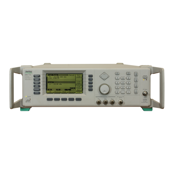
Anritsu 681 C Series Maintenance Manual (317 pages)
SYNTHESIZED CW/SIGNAL GENERATORS
Brand:
Anritsu
| Category:
Portable Generator
| Size: 3 MB
Table of Contents
Table of Contents
6
Description
14
Introduction
14
Scope of Manual
14
Electronic Manual
16
GPIB Programming Manual
16
Identification Number
16
Operation Manual
16
Related Manuals
16
SCPI Programming Manual
16
Options
17
Calibration
19
Level of Maintenance
19
Precautions
19
Preventive Maintenance
19
Repair
19
Static-Sensitive Component Handling
19
Troubleshooting
19
Handling Precautions
20
Static-Sensitive Component
20
Preventive Maintenance
21
Startup Configurations
22
Recommended Test Equipment
23
Exchange Assembly Program
25
Replaceable Subassemblies and Parts
25
690Xxb/691Xxb Major Subsystems
32
Digital Control
32
Introduction
32
Frequency Synthesis
33
Front Panel
33
Analog Instruction
34
YIG, SDM, SQM Driver
34
Alc/Modulation
37
Inputs/Outputs
37
Power Supply
37
RF Deck
37
Frequency Synthesis
38
Motherboard/Interconnections
38
Phase Lock Loops
38
Overall Operation
39
RF Outputs 0.00001 to 65 Ghz
42
Frequency Modulation (691XXB Only)
43
Alc and Modulation
44
ALC Loop Operation
44
Step Sweep Mode
44
Amplitude Modulation (691XXB Only)
47
Square Wave Modulation (691XXB Only)
47
Rf Deck Assemblies
49
YIG-Tuned Oscillator
49
RF Signal Filtering
54
To 2 Ghz down Converter
55
To 2.2 Ghz Digital down Converter
56
Switched Doubler Module
57
Source Quadrupler Module
58
Power Level Detection/Alc Loop
59
Step Attenuators
60
Connector and Key Label Notation
64
Introduction
64
Recommended Test Equipment
64
Test Records
64
690Xxb/691Xxb Power Levels
67
Internal Time Base Aging Rate Test
68
Test Setup
68
Test Procedure
69
Test Setup
71
Fine Loop Test Procedure
72
Ghz Test Procedure
73
SPURIOUS SIGNALS TEST: RF OUTPUT SIGNALS £2 Ghz (£2.2 Ghz UNITS W/OPTION 21A)
73
Test Setup
73
2.2 Ghz Test Procedure
76
Ghz Test Procedure
78
HARMONIC TEST: RF OUTPUT SIGNALS from 2 to 20 Ghz
78
Ghz Test Procedure
79
Single Sideband Phase Noise Test
81
Test Setup
81
Test Procedure
82
Power Level Accuracy and Flatness Tests
86
Power Level Accuracy Test Procedure
86
Power Level Flatness Test Procedure
87
Amplitude Modulation Test
91
Frequency Modulation Tests
92
Test Setup
92
FM Input Sensitivity Procedure
93
Introduction
100
Recommended Test Equipment
100
Test Records
100
Calibration Following Subassembly
101
Calibration Following Subassembly Replacement
101
Connector and Key Label Notation
101
Replacement
101
Initial Setup
104
Interconnection
104
PC Setup - Windows 3.1
105
PC Setup - Windows 95/Windows 98
107
Equipment Setup
110
Preliminary Calibration
110
Calibration Steps
111
Alternate Reference Oscillator Calibration
114
Equipment Setup
116
Switched Filter Shaper Calibration
116
Limiter DAC Adjustment
117
Log Amplifier Zero Calibration
117
Shaper DAC Adjustment
119
Rf Level Calibration
120
Alc Slope Calibration (691Xxb Only)
121
Equipment Setup
121
ALC Slope DAC Adjustment
122
Alc Bandwidth Calibration
125
Bandwidth Calibration
125
Equipment Setup
125
Alc Bandwidth Calibration
126
Equipment Setup
127
AM Calibration Procedure
128
Equipment Setup
131
Fm Calibration (691Xxb Only)
131
FM Calibration Procedure
132
Error and Warning/Status Messages
138
Introduction
138
Recommended Test Equipment
138
Self-Test Error Messages
138
Error and Warning/Status Messages
142
Messages
142
Normal Operation Error and Warning/Status
142
Status Messages
142
Malfunctions Not Displaying an Error Message
145
Troubleshooting Tables
145
Troubleshooting Tables
147
Introduction
188
Covers
189
Preliminary
189
Procedure
189
Removing and Replacing the Chassis
189
Removing and Replacing the Chassis Covers
189
Panel Assembly
191
Preliminary
191
Procedure
191
Removing and Replacing the Front
191
Removing and Replacing the Front Panel Assembly
191
Preliminary
193
Procedure
193
Removing and Replacing the A3, A5, or A6 Pcb
193
Removing and Replacing the A4 Pcb
193
Preliminary
195
Procedure
195
Removing and Replacing the A7 Pcb
195
Removing and Replacing the A9, A10, A11, or A12 Pcb
195
Preliminary
196
Procedure
196
Removing and Replacing the A13 or A15 Pcb
196
Or A17 Pcb
198
Or A19 Pcb
198
Preliminary
198
Procedure
198
Removing and Replacing the A16
198
Removing and Replacing the A18
198
Panel Assembly
199
Preliminary
199
Procedure
199
Removing and Replacing the Rear Panel Assembly
199
Preliminary
202
Procedure
202
Removing and Replacing the A21 Pcb
202
Preliminary
203
Procedure
203
Removing and Replacing the A21-1
203
Removing and Replacing the A21-1/A21-2 Pcb
203
Preliminary
204
Procedure
204
Removing and Replacing the Fan Assembly
204
Appendix A Test Records
206
Introduction
206
Advertisement
Anritsu 681 C Series Operation Manual (242 pages)
SYNTHESIZED SIGNAL GENERATOR
Brand:
Anritsu
| Category:
Portable Generator
| Size: 3 MB
Table of Contents
Table of Contents
7
Scope of Manual
15
Introduction
15
Description
15
Identification Number
17
Electronic Manual
17
Related Manuals
17
GPIB Programming Manual
17
SCPI Programming Manual
17
Maintenance Manual
18
Options
18
Performance Specifications
19
Recommended Test Equipment
20
Introduction
23
Initial Inspection
23
Preparation for Use
24
Power Requirements
24
Line Voltage Selection
24
Power Connection
24
Standby Operation
25
Preparation for Use
25
Warmup Time
26
Operating Environment
26
Gpib Setup and Interconnection
27
Interface Connector
27
Cable Length Restrictions
27
GPIB Interconnection
27
Setting the GPIB Address
27
Selecting the Line Terminator
29
Selecting the Interface Language
29
Rack Mounting Kit Installation
30
Preliminary
30
Procedure
30
Preparation for Storage/Shipment
33
Preparation for Storage
33
Preparation for Shipment
33
Introduction
39
Line Key
40
RF Output Control Key
41
Connectors
41
Data Display Area
42
Menu Display Format
43
Menu Keys
44
Data Entry Area
46
Instrument Start-Up
48
Powering up the 681XXC
48
Start-Up Display
48
Standby Operation
48
Self-Testing the 681XXC
49
Resetting to Default Parameters
49
Cw Frequency Operation
55
Selecting CW Mode
55
Selecting a CW Frequency
56
Selecting a Power Level
58
CW Ramp
59
Sweep Frequency Operation
60
Selecting Analog Sweep Mode
60
Selecting a Sweep Trigger
62
Step Sweep Mode
63
Setting Step Size, Dwell Time, and Sweep Time
63
Selecting Manual Sweep Mode
66
Selecting a Sweep Range
67
Selecting a Power Level
69
Frequency Markers
70
Selecting Alternate Sweep Mode
72
List Sweep Mode
75
Selecting List Sweep Mode
76
Editing the List
77
Selecting a List Sweep Range
80
Selecting a List Sweep Trigger
81
Fixed Power Level Operation
83
Selecting Fixed Power Level Mode
83
Selecting a Power Level
83
Level Offset
86
Power Level Sweep Operation
88
Dwell Time
88
Selecting a CW Power Sweep Trigger
89
Selecting a Power Level Sweep Range
90
Selecting a Sweep Frequency/Step Power Mode
92
Setting Power Level Step Size
93
Leveling Operations
97
Attenuator Decoupling
98
ALC Power Slope
99
User Cal (User Level Flatness Correction)
101
Signal Modulation
107
Amplitude Modulation Operating Modes
107
Providing Amplitude Modulation
107
Frequency Modulation Operating Modes
108
Providing Frequency Modulation
109
Square Wave Modulation Operating Modes
111
Providing Square Wave Modulation
111
System Configuration
114
Configuring the Front Panel
115
Configuring the Rear Panel
116
Configuring the RF
117
Configuring the GPIB
119
Setting Increment Sizes
122
Saving/Recalling Instrument Setups
123
Saving Setups
123
Recalling Setups
123
Erasing Stored Setups
124
Secure Operation
125
Reference Oscillator Calibration
126
Sample Menu Map
132
CW Frequency Mode Menu Map
133
Analog Sweep Frequency Mode Menu Map
134
Step Sweep Frequency Mode Menu Map
135
Manual Sweep Frequency Mode Menu Map
136
List Sweep Frequency Mode Menu Map
137
CW Power Sweep Mode Menu Map
139
Sweep Frequency/Step Power Mode Menu Map
140
Leveling Modes Menu Map
141
Amplitude Modulation Mode Menu Map
142
Frequency Modulation Mode Menu Map
143
System Configuration Menu Map
145
Introduction
148
Test Equipment
148
Test Records
148
Initial 681Xxc Checkout
149
Power up
149
Self Test
149
Resetting the 681XXC
149
Warmup Time
149
Cw Frequency Accuracy Test
150
Test Setup
150
Test Procedure
151
Power Level Accuracy and Flatness Tests
158
Test Setup
158
Power Level Accuracy Test Procedure
159
Power Level Flatness Test Procedure
160
Introduction
193
Error and Warning/Status Messages
193
Self-Test Error Messages
193
Messages
193
Troubleshooting
200
Routine Maintenance
203
Cleaning the Fan Filter
203
Cleaning the Data Display
203
Replacing the Line Fuse
204
Introduction
208
Master-Slave Operation
209
Connecting the Instruments
209
Initiating Master-Slave Operation
210
Master-Slave Operation
210
Master-Slave Operation in VNA Mode
212
Terminating Master-Slave Operation
214
Use with a 56100A Scalar Network Analyzer
215
Connecting the 681XXC to the 56100A
215
Use with a 360B Vector Network Analyzer
216
Connecting the 681XXC to the 360B
216
Modes of Operation
217
Source Lock Mode
217
Tracking Mode
219
Use with a Hp8757D Scalar Network Analyzer
221
Connecting the 681XXC to the HP8757D
221
Setting up the 681XXC
222
Initiating HP8757D SNA Operation
224
Advertisement
Related Products
Anritsu 68117C
Anritsu 68137C
Anritsu 68147C
Anritsu 68167C
Anritsu 68177C
Anritsu 68187C
Anritsu 68197C
Anritsu 681 B Series
Anritsu 680 C Series
Anritsu 680 B Series
Anritsu Categories
Measuring Instruments
Test Equipment
Portable Generator
Control Unit
Thermometer
More Anritsu Manuals
Login
Sign In
OR
Sign in with Facebook
Sign in with Google
Upload manual
Upload from disk
Upload from URL