Sign In
Upload
Manuals
Brands
Amazone Manuals
Farm Equipment
Cataya 3000 Special
User Manuals: Amazone Cataya 3000 Special Seed Drill
Manuals and User Guides for Amazone Cataya 3000 Special Seed Drill. We have
1
Amazone Cataya 3000 Special Seed Drill manual available for free PDF download: Operating Manual
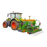
Amazone Cataya 3000 Special Operating Manual (243 pages)
Pack top seed drill
Brand:
Amazone
| Category:
Farm Equipment
| Size: 57 MB
Table of Contents
Table of Contents
5
1 User Information
10
2 General Safety Instructions
11
Obligations and Liability
11
Representation of Safety Symbols
13
Organisational Measures
14
Safety and Protective Equipment
14
Informal Safety Measures
14
User Training
15
Safety Measures in Normal Operation
16
Danger from Residual Energy
16
Maintenance and Repair Work, Fault Elimination
16
Design Changes
16
Spare and Wear Parts and Aids
17
Cleaning and Disposal
17
Workstation of the Operator
17
Warning Symbols on the Implement
18
Position of Warning Symbols
25
Dangers in Case of Non-Compliance with the Safety Instructions
26
Safety-Conscious Working
26
Safety Information for Users
27
General Safety Instructions and Accident Prevention Instructions
27
Hydraulic System
31
Electrical System
32
Mounted Implements
33
Operation of the Seed Drill
34
Cleaning, Maintenance and Repair
34
3 Loading and Unloading the Implement Upon Delivery
35
4 Product Description
37
Components of the AMAZONE Seeding Combination
37
Equipment Variations of the Cataya Pack Top Seed Drill
38
Assembly Groups of the Cataya Pack Top Seed Drill
40
Safety and Protective Equipment
42
Overview - Supply Cable / Hydraulic Hose Lines
43
Supply Cable
43
Identification of the Hydraulic Hose Lines
43
Connection and Function of the Tractor Control Units with and Without ISOBUS System
44
Traffic Safety Equipment
45
Proper Use
46
Approved AMAZONE Implement Combinations
47
Danger Areas and Danger Points
48
Rating Plate and CE Mark
49
Technical Specifications
50
Noise Production Data
50
Technical Data for Calculating the Tractor Weight and the Tractor Axle Loads
51
Required Tractor Equipment
52
Operating Pressure of the Hydraulic System
52
5 Structure and Function
53
AMAZONE Amalog+ Control Terminal
56
AMAZONE Amadrill 2 Control Terminal
56
AMAZONE Calibration Button
57
Control Terminal for Implements with ISOBUS System
57
AMAZONE Amatron 4 Control Terminal
58
AMAZONE Twinterminal
58
Implement Documentation
59
Central Key
59
Star Wheel
60
Radar Sensor
61
Seed Hopper and Loading Board
62
Fill Level Monitoring
63
Seeding Shaft Drive
64
Seeding Shaft Drive of One Star Wheel
64
5.11.1.1 Extending the Range of the Vario Gearbox
65
Seeding Shaft Drive, Electrically Regulated
65
Metering
66
Setting Values
68
5.12.1.1 Coarse and Fine Metering Wheel
70
5.12.1.2 Bean Metering Wheel
70
5.12.1.3 Bottom Flaps
71
5.12.1.4 Slide Gate
72
5.12.1.5 Agitator Shaft Support
72
Seed Rate Calibration
73
Calibration - Implements with Star Wheel Drive
76
Calibration - Implements with Electric Seeding Shaft Drive
79
WS Coulter
80
Band Seeding Shoe
80
Rotec Control Coulter
81
Coulter Pressure Rotec
83
Coulter Pressure Adjustment, Manually Actuated
83
Coulter Pressure, Hydraulically Actuated with Seed Rate Increase
84
Twintec Special Double Disc Coulter
86
Seed Placement Depth (Twintec Special)
88
Coulter Pressure (Twintec Special)
89
Coulter Lift - Soil Tillage Without Seeding
90
Exact Following Harrow
91
Exact Following Harrow Tine Position
92
Exact Following Harrow Pressure
93
Tramlines
94
Tramline Rhythm, Tabular Determination
97
Tramline Rhythm, Graphic Determination
98
One-Sided Switching
100
Tramline Marker
101
Track Marker
102
Seed Guide Elements
102
Work Floodlights
103
Coulter Array Lighting
103
Camera System
103
6 Initial Operation
104
Checking the Suitability of the Tractor
105
Calculating the Actual Values for the Total Tractor Weight, Tractor Axle Loads and Tyre Load-Bearing Capacity, as Well as the Required Minimum Ballast Weight
106
Data Required for the Calculation (Attached Implement)
107
Calculation of the Required Minimum Ballast Weight at the Front G
108
To Ensure Steering Capability
108
Min of the Tractor
108
Calculation of the Actual Front Axle Load of the Tractor T
108
Calculation of the Actual Total Weight of the Combined Tractor and Implement
108
Tat
108
Calculation of the Actual Rear Axle Load of the Tractor T
108
Load-Bearing Capacity of the Tractor Tyres
108
H Tat
108
Table
109
Secure the Tractor / Implement against Unintentional Starting and Rolling Away
110
7 Coupling and Uncoupling the Implement
111
Hydraulic Hose Lines
113
Coupling the Hydraulic Hose Lines
113
Disconnecting the Hydraulic Hose Lines
114
Coupling and Uncoupling Implements
115
Coupling - Tractor and Soil Tillage Implement
117
Coupling - Pack Top Seed Drill and Soil Tillage Implement
118
Uncoupling - Combination from the Tractor
123
Uncoupling - Soil Tillage Implement and Pack Top Seed Drill
124
Checking the Tramline Track Width
128
Checking the Tramline Wheelmark Width
128
8 Settings
129
Folding the Steps up and down
130
Fill the Seed Hopper
132
Adjusting the Implement to Type of Seed
137
Bottom Flap Position
137
Sliding Shutter Position
138
Agitator Shaft Support
139
Agitator Shaft Support (Implements with Star Wheel Drive)
139
Agitator Shaft Support (Implements with Electric Metering Drive)
140
Calibrating the Seed Rate
141
Calibrating the Seed Rate - Implements with Star Wheel Drive
145
Preparing the Implement for Calibration
145
Pre-Calibrating the Implement
146
Calibrating the Seed Rate
147
Determining the Gearbox Setting Using the Calculating Disc Rule
149
Calibrating the Seed Rate - Implements with Amadrill 2 Control Terminal or Implements with ISOBUS System
150
Adjusting the Automatic Seed Rate Increase
151
Star Wheel - Working and Transport Position
152
Rotec Control Coulter
153
Adjusting and Checking the Seed Placement Depth
153
Adjusting the Depth Control Discs / Wheels
154
Attaching the Band Seeding Shoe to the WS Coulter
155
Coulter Pressure - Rotec and WS Coulter
156
Coulter Pressure Adjustment (Manual Adjustment)
156
Coulter Pressure Adjustment (Hydraulic Adjustment)
157
Twintec Double Disc Coulter
158
Adjusting and Checking the Seed Placement Depth
158
Adjusting the Twintec Harrow Tines
158
Coulter Pressure (Manually Actuated)
161
Adjusting the Exact Following Harrow
162
Adjusting the Exact Following Harrow Tines by Rebolting the Brackets
162
Infinitely Variable Adjustment of the Exact Following Harrow Tines
162
Setting the Exact Following Harrow Pressure
163
Moving the Exact Following Harrow to the Working/Transport Position
164
8.10.4.1 Move the Exact Following Harrow into Working Position
164
8.10.4.2 Moving the Exact Following Harrow into Transport Position
164
Moving the Track Marker to the Working / Transport Position
165
One-Sided Switching
166
Moving the Tramline Marker into Working/Transport Position
167
Move the Tramline Marker to Working Position
167
Move the Tramline Markers to the Transport Position
168
Moving the Exact Following Harrow Road Safety Bar into Road Transport/Parking Position
169
Moving the Road Safety Bar into Road Transport Position
169
Moving the Road Safety Bar into Parking Position
169
Soil Tillage Without Seeding
170
Lifting the Coulters and Exact Following Harrow
170
Moving the Coulters and Exact Following Harrow into Working Position
171
9 Transportation
172
Moving the Seeding Combination into Transport Position
172
Legal Regulations and Safety
173
10 Use of the Implement
177
Initial Operation
178
Work Floodlights
178
Coulter Array Lighting
179
Moving the Implement from Transport into Working Position
179
Work Commencement
179
During Operation
181
Overview of Checks During Operation
181
Turning at End of the Field
182
Track Marker
183
End of Work on the Field
184
Emptying the Seed Hopper and Seed Housing
185
11 Faults
189
Residual Seed Quantity Display
190
Deviations between the Set and Actual Seed Rate
190
12 Maintenance and Repairs
191
Maintenance Schedule
191
Safety
193
Safety When Cleaning the Implement
194
Safety When Working on the Hydraulic System
195
Repairs
196
Visual Inspection of the Upper and Lower Link Pins
196
Visual Check of the Hydraulic Hose Lines and Couplings
197
12.3.2.1 Date of Manufacture of the Hydraulic Hose Line
197
Check the Chain Tension
198
Bottom Flaps, Check Basic Position
199
Vario Gearbox, Check the Oil Level
200
Checking / Readjusting / Replacing the Twintec Roller Scrape
201
Opening the Protective Equipment
202
Open the Function Flap
202
Opening the Cover
203
Installations
204
Shutdown of the Implement over a Long Period of Time
204
Adjusting the Tramline Control
205
12.5.2.1 Folding down the Lay Shaft
207
12.5.2.2 Folding up the Lay Shaft
208
12.5.2.3 Setting the Tramline Track Width
209
12.5.2.4 Setting the Tramline Wheelmark Width
210
12.5.2.5 Conversion of a Metering Wheel to a Tramline Metering Wheel
211
12.5.2.6 Conversion of a Tramline Metering Wheel to a Metering Wheel
213
Conversion of a Tramline Metering Wheel to a Metering Wheel by Shifting the Gear Wheel on the Lay Shaft
213
Conversion of a Tramline Metering Wheel to a Metering Wheel by Removing the Gear Wheel Pairing from the Lay Shaft and Seeding Shaft
214
Changing the Metering Wheel
215
12.5.3.1 Changing the Metering Wheel - Seeding Shaft Drive with Star Wheel
215
12.5.3.2 Changing the Metering Wheel - Seeding Shaft Drive with an Electric Motor
220
Extending the Range of the Vario Gearbox
226
Extending the Range of the Vario Gearbox by Moving the Double Chain Wheel on the Drive Shaft
227
Extending the Range of the Vario Gearbox by Replacing the Double Chain Wheel with a Double Chain Wheel with a Different Number of Cogs
228
Workshop Work
230
Checking the Hydraulic Hose Lines
230
12.6.1.1 Safety When Working on Hydraulic Hose Lines
231
Checking and Readjusting the Twintec Disc Bearings
232
12.6.2.1 Checking the Twintec Disc Bearings
232
12.6.2.2 Readjusting the Twintec Disc Bearings
232
Checking / Replacing the Twintec Inner Scraper
234
Checking / Replacing the Twintec Baffle Lip
235
12.6.4.1 Installation Instruction: Removing the Twintec Seed Line
236
Checking / Replacing the Twintec Press Roller
236
Oils and Greases
237
Lubricants for Grease Nipples and Grease Guns
237
Vario Gearbox Gear Oil
237
Bolt Tightening Torques
238
13 Hydraulic Diagram
239
Cataya 3000 Special Hydraulic Diagram with and Without ISOBUS System
239
Advertisement
Advertisement
Related Products
Amazone Centaya 3000 Super 1600
Amazone Cirrus 3002
Amazone Catros 3003 Special
Amazone Precea 3000-CC
Amazone Precea 3000-FCC
Amazone Ceus 3000-TX
Amazone Precea 3000-A
Amazone Precea 3000-ACC
Amazone Precea 3000-AFCC
Amazone Catros 3503 Special
Amazone Categories
Farm Equipment
Tiller
Spreader
Desktop
Paint Sprayer
More Amazone Manuals
Login
Sign In
OR
Sign in with Facebook
Sign in with Google
Upload manual
Upload from disk
Upload from URL