Sign In
Upload
Manuals
Brands
Amada Manuals
Power Supply
HF2
Amada HF2 Manuals
Manuals and User Guides for Amada HF2. We have
1
Amada HF2 manual available for free PDF download: Operation Manual
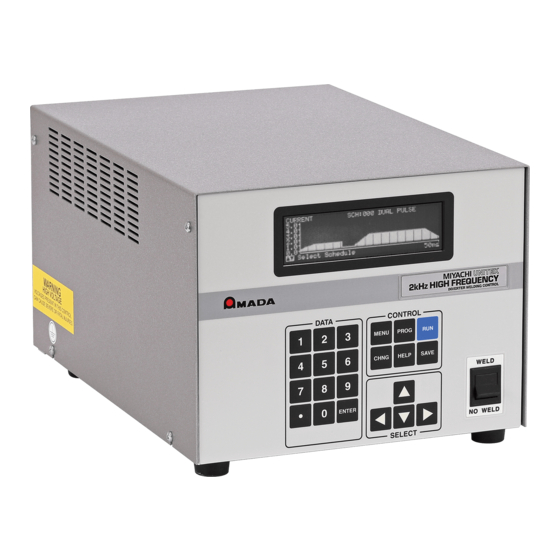
Amada HF2 Operation Manual (134 pages)
INVERTER WELDING POWER SUPPLY
Brand:
Amada
| Category:
Power Supply
| Size: 5.88 MB
Table of Contents
Table of Contents
4
Chapter 2: General Set-Up
19
Required Connections
19
Physical Space Requirements
19
HF2 Welding Power Supply Dimensions
19
HF2 Welding Transformer Dimensions
19
Power Line Voltage, Current, and Wire Size Requirements
20
Insulation Requirements
20
Power Line Fuse Requirements
20
HF2 Welding Transformer Electrical Specifications
21
HF2 Welding System Maximum Secondary Loop Resistance
22
HF2 Maximum Secondary Loop Resistance Measurement
22
HF2 Welding Power Supply to HF2 Welding Transformer Connections
22
HF2 Welding Transformer to Weld Head Connections
23
Weld Sentry Option
23
Help Screen Languages
23
Chapter 3: Welding System Set-Up
25
Welding System Set-Up Guide
25
General Programming Instructions
25
CHAPTER 3: WELDING SYSTEM SET-UP (Continued)
25
AMADA WELD TECH Force Fired, Foot Actuated Weld Head System
26
Weld Head Set-Up
26
Firing Switch Cable Connection
26
Quick Start Programming Guide
26
AMADA WELD TECH Force Fired, Single Air Actuated Weld Head System
28
Weld Head Set-Up
28
Firing Switch Cable Connection
28
Weld Head Valve Driver No. 1 Connection
28
Foot Switch Connection
28
Single Air Regulator Adjustment (TL-080B Series Weld Heads)
29
Dual Air Regulator Adjustments (TL-180B Weld Heads)
30
Quick Start Programming Guide
30
AMADA WELD TECH Force Fired, Dual Air Actuated Weld Head System
31
General Information
31
Power Supply, Jumper Modifications
31
Weld Head Set-Up
32
Firing Switch Cable Connection
33
Weld Head Valve Driver Connections
33
Foot Switch Connection
33
Dual Air Regulator Adjustment
34
Quick Start Programming Guide
38
PLC to Power Supply Electrical Connections
40
PLC Timing Diagram
41
Quick Start Programming Guide
41
Chapter 4: Controls
45
Power Supply Front Panel
45
Power Supply - Rear Panel Inputs and Outputs
47
Power
47
Fuses F1, F2
47
Sensing Port
47
Sensing Port - Connector Pin Assignments
48
Output
48
Foot Switch Connector
49
Single-Level Foot Switch
49
Two-Level Foot Switch
49
Firing Switch Operation
50
Mechanical Firing Switch Cable
50
Optical Firing Switch Connector
50
Mechanical Firing Switch - 3-Wire Connection
51
Opto-Coupler Firing Switch - 3-Wire Connection
51
Control Signals Connector
51
Control Signals - Pin Assignments
52
Control Signals - Remote Weld Schedule Selection Input
53
Control Signals - Emergency Stop Input
53
Control Signals - Process Inhibit Input
53
Control Signals - Output Relays
54
Relay K1
54
Relay K2
54
Accessory Port
54
Air Valve 1 and Air Valve 2 Driver Connectors
55
Air Valve 1 Driver
55
Air Valve 2 Driver
55
Chapter 5: Programming Modes
57
Help Screens
57
Machine States
57
Weld Graph Run State
57
Basic Weld Monitor Run State
58
Alphanumeric Run State
58
No Weld State
58
Standby State
58
Alarm State
59
Fire State
59
Menu State
59
Program State
60
Weld Graph Program State
60
Alphanumeric Program State
61
Output Relays
62
Relay 1 - Dual Air Head Operation
63
Weld Functions
65
Basic Weld
65
Weld/Repeat
65
Quench/Temper
65
Pre/Postheat
65
Up/Downslope
65
Braze
72
Rollspot
73
Seam
74
Dual Pulse
76
Pulsation
77
Chapter 7: Special Features
79
System Options
79
Weld Counter
86
Copy a Schedule
87
System Security
87
System Help
89
Weld Sentry
89
Calibrate the Power Supply
89
Reset to Defaults
89
Installation
91
Transformer Model
91
Chapter 8: Weld Monitoring
93
Basic Weld Monitor General Description
93
Weld Current and Weld Voltage Measurements
94
Data Output Capabilities
94
Weld Monitoring Suggestions
94
Basic Weld Monitor Programming
95
Energy Limit Monitor General Description
96
Energy Limit Monitor Programming
97
Appendix A: Technical Specifications
99
Appendix C: Recommended Spare Parts
105
Appendix Dalarm Messages
107
Appendix E: Help Screen Languages
111
Appendix F: Replacement of Programmed Integrated Circuits
113
Appendix G: the Basics of Resistance Welding
115
Appendix H: Quality Resistance Welding Solutions: Defining the Optimum Process
121
Advertisement
Advertisement
Related Products
Amada HF2S
Amada HF25
Amada HF28/240
Amada HF28/400
Amada HF28/480
Amada HF-2500A
Amada HFA-250
Amada HFA-400W
Amada HFA-250W
Amada HFA-400
Amada Categories
Welding System
Welding Accessories
Power Supply
Transformer
Indoor Furnishing
More Amada Manuals
Login
Sign In
OR
Sign in with Facebook
Sign in with Google
Upload manual
Upload from disk
Upload from URL