Sign In
Upload
Manuals
Brands
Allen-Bradley Manuals
Controller
PowerFlex40
User Manuals: Allen-Bradley PowerFlex40 AC Drive
Manuals and User Guides for Allen-Bradley PowerFlex40 AC Drive. We have
1
Allen-Bradley PowerFlex40 AC Drive manual available for free PDF download: User Manual
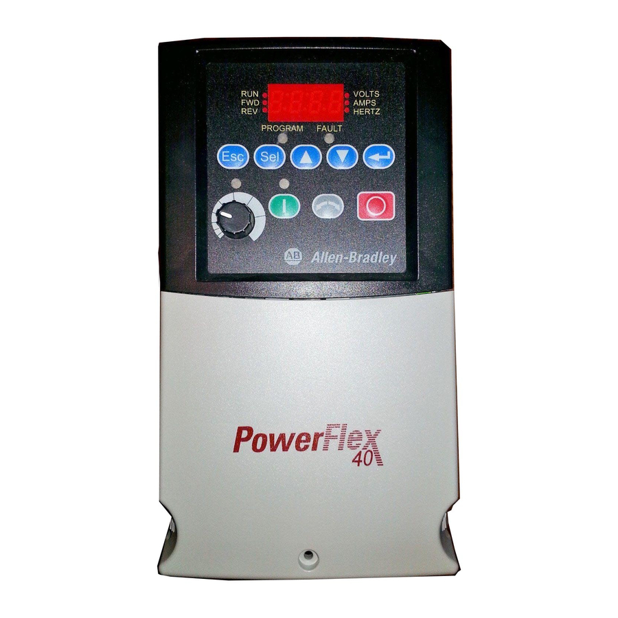
Allen-Bradley PowerFlex40 User Manual (161 pages)
Adjustable Frequency AC Drive
Brand:
Allen-Bradley
| Category:
Controller
| Size: 5 MB
Table of Contents
Chapter 1 Installation/Wiring
11
Opening the Cover
11
IP66, NEMA/UL Type 4X
12
IP66, NEMA/UL Type 4X Cover Installation
12
A Enclosure and Clearance Requirements
13
Ambient Operating Temperatures
13
Minimum Mounting Clearances
13
Mounting Considerations
13
Debris Protection
14
Storage
14
AC Supply Source Considerations
15
Phase to Ground MOV Removal
15
Ungrounded Distribution Systems
15
Input Power Conditioning
16
General Grounding Requirements
17
Ground Fault Monitoring
17
Safety Ground
17
Typical Grounding
17
Fuses and Circuit Breakers
18
Fusing
18
RFI Filter Grounding
18
Minimum Recommended Branch Circuit Protective Devices
19
Motor Cable Types Acceptable for 200-600 Volt Installations
20
Power Wiring
20
Shielded/Armored Cable
20
Unshielded
20
Recommended Shielded Wire
21
Maximum Cable Length Recommendations
22
Output Disconnect
22
Reflected Wave Protection
22
Power Terminal Block
23
Power Terminal Block Specifications
23
I/O Wiring Recommendations
24
IP66, NEMA/UL Type 4X Installations
24
Motor Start/Stop Precautions
24
Control Wire Types
25
I/O Terminal Block
25
Maximum Control Wire Recommendations
25
Recommended Control and Signal Wire
25
Control Wiring Block Diagram
26
H Control I/O Terminal Designations
27
Analog Input
28
Analog Input, PTC
28
I/O Wiring Examples
28
Potentiometer
28
Typical Multiple Drive Connection Examples
32
Start and Speed Reference Control
33
Accel/Decel Selection
34
EMC Instructions
35
Allowable Cable Length
36
Connections and Grounding
36
Essential Requirements for CE Compliance
36
Before Applying Power to the Drive
39
Prepare for Drive Start-Up
39
Start up
39
Applying Power to the Drive
40
Start, Stop, Direction and Speed Control
40
Variable Torque Fan/Pump Applications
41
Integral Keypad
42
Viewing and Editing Parameters
43
Remote HIM Menu Structure
44
Device Select Menu
45
Diagnostics Menu
45
HIM Setup Menu
45
Parameters Menu
45
Important User Information
2
Summary of Changes
3
New Parameter
4
Parameter Updates
4
Table of Contents
5
Overview
7
Reference Materials
7
Who Should Use this Manual
7
Drive Frame Sizes
8
Manual Conventions
8
General Precautions
9
Catalog Number Explanation
10
Chapter 2 Start up
47
Chapter 3 Programming and Parameters
47
About Parameters
47
Enum
47
Numeric Parameters
47
Parameter Organization
48
Display Group
49
Output Freq
49
Commanded Freq
49
Output Voltage
49
Drive Status
50
Process Display
50
Control Source
51
Contrl in Status
51
Dig in Status
52
Comm Status
52
Control SW Ver
52
Drive Type
52
Elapsed Run Time
53
Testpoint Data
53
Analog in 0-10V
53
Analog in 4-20Ma
53
Drive Temp
54
Counter Status
54
Timer Status
54
Stp Logic Status
54
Basic Program Group
55
Motor NP Volts
55
Motor NP Hertz
55
Motor OL Current
55
Start Source
56
Stop Mode
57
Hardware Enable Circuitry
57
Speed Reference
58
Accel Time 1
58
Decel Time 1
59
Reset to Defalts
59
Voltage Class
59
Motor OL Ret
59
Advanced Program Group
60
Relay out Sel
62
A056 [Relay out Level]
63
Opto Out1 Sel
64
Opto Out2 Sel
64
Opto out Logic
66
Analog out Sel
66
Analog out High
67
Accel Time 2
67
Decel Time 2
68
Internal Freq
68
Jog Frequency
69
Jog Accel/Decel
70
DC Brake Time
70
DC Brake Level
70
DB Resistor Sel
71
S Curve %
71
Boost Select
72
Start Boost
73
Break Voltage
73
Break Frequency
73
Maximum Voltage
74
Current Limit 1
74
Motor OL Select
74
PWM Frequency
74
Auto Rstrt Tries
75
Auto Rstrt Delay
75
Start at Powerup
75
Reverse Disable
76
Flying Start en
76
Compensation
76
SW Current Trip
76
Fault Clear
77
Program Lock
77
Testpoint Sel
77
Comm Data Rate
77
Comm Loss Action
78
Comm Loss Time
78
Comm Format
78
Language
78
Anlg out Setpt
79
Anlg in 0-10V lo
79
Anlg in 0-10V Hi
79
Anlg In4-20Ma lo
79
Anlg In4-20Ma Hi
80
Slip Hertz @ FLA
80
Process Time lo
80
Process Time Hi
80
Skip Frequency
81
Skip Freq Band
81
Stall Fault Time
81
Analog in Loss
82
10V Bipolar Enbl
82
Var PWM Disable
82
Torque Perf Mode
82
Autotune
83
IR Voltage Drop
83
Flux Current Ref
83
PID Trim Hi
84
PID Trim lo
84
PID Ref Sel
84
PID Feedback Sel
84
PID Integ Time
85
PID Diff Rate
85
PID Setpoint
85
PID Deadband
85
How Steplogic Works
86
Digit 0: Logic for Next Step
86
Digit 1: Logic to Jump to a Different Step
86
Digit 2: Different Step to Jump
86
Values Default
86
Display
86
Digit 3: Step Settings
87
Steplogic Settings
87
Display
88
EM Brk off Delay
88
Select the Source of the PID Feedback. Refer to Appendix F for Details.
88
Values Default
88
Min/Max
88
DB Threshold
89
EM Brk on Delay
89
MOP Reset Sel
89
Analog in Filter
90
Anlg Loss Delay
90
Comm Write Mode
90
PID Invert Error
90
Parameter Cross Reference – by Name
91
Chapter 4 Troubleshooting
93
Faults
93
Drive Status
93
Fault Indication
94
Manually Clearing Faults
94
Automatically Clearing Faults
94
Auto Restart (Reset/Run)
94
Fault Descriptions
95
Common Symptoms and Corrective Actions
97
Motor Does Not Start
97
Motor Operation Is Unstable
100
Drive will Not Reverse Motor Direction
100
Drive Does Not Power up
100
Supplemental Drive Information
101
Drive, Fuse & Circuit Breaker Ratings
101
Circuit Breakers
101
Specifications
101
Specifications
102
Drive Ratings
102
Input/Output Ratings
103
Control Output
103
Protective Features
103
Dynamic Braking
103
Appendix B Accessories and Dimensions
107
Product Selection
107
Catalog Number Description
107
Powerflex 40 Drives
107
Dynamic Brake Modules
108
Bulletin 1321-3R Series Line Reactors
109
DC Bus Inductors
109
EMC Line Filters
110
Human Interface Module (HIM) Option Kits and Accessories
111
IP30/NEMA 1/UL Type 1 Kit
111
Communication Option Kits and Accessories
112
Product Dimensions
113
Powerflex 40 Frames – Ratings Are in Kw and (HP)
113
IP20, NEMA/UL Type Open
113
IP30, NEMA/UL Type 1 Option Kit with Communication Option
114
Powerflex 40 Flange Mount Drives
115
Frame B EMC Line Filters
121
Frame C EMC Line Filters
122
Remote (Panel Mount) Small HIM
123
NEMA Type 1 Bezel
124
RS485 (DSI) Protocol
125
Network Wiring
125
Network Wiring Diagram
125
Parameter Configuration
127
Supported Modbus Function Codes
127
Writing (06) Logic Command Data
128
Writing (06) Reference
129
Reading (03) Logic Status Data
129
Reading (03) Feedback
130
Reading (03) Drive Error Codes
130
Reading (03) and Writing (06) Drive Parameters
131
Additional Information
131
Appendix A Supplemental Drive Information
107
Accessories and Dimensions
107
Appendix C RS485 (DSI) Protocol
133
RJ45 DSI Splitter Cable
133
Connectivity Guidelines
133
DSI Cable Accessories
134
RJ45 Splitter Cable
134
RJ45 Two-Position Terminal Block Adapter
134
RJ45 Adapter with Integrated Termination Resistor
134
Connecting One Temporary Peripheral and One Permanent Peripheral
135
Connecting Two Permanent Peripherals
136
Connecting an RS-485 Network
136
Appendix D RJ45 DSI Splitter Cable
137
Steplogic, Basic Logic and Timer/Counter Functions
137
Basic Logic Function
137
Timer Function
137
Counter Function
137
Appendix E Steplogic, Basic Logic and
138
Steplogic Using Timed Steps
138
Steplogic Sequence
138
Steplogic Using Basic Logic Functions
139
Timer Function
140
Counter Function
142
Steplogic Parameters
143
Code Descriptions for Parameters A140-A147
143
PID Set up
145
Appendix F PID Set up
145
PID Loop
145
Exclusive Control
146
Trim Control
147
PID Reference and Feedback
148
Analog PID Reference Signals
149
Scale Function
149
Invert Function
150
PID Preload
151
PID Limits
151
PID Gains
152
PID Prop Gain
152
Guidelines for Adjusting the PID Gains
153
Unstable
154
Slow Response – over Damped
154
Oscillation – under Damped
154
Good Response – Critically Damped
154
Index
155
Advertisement
Advertisement
Related Products
Allen-Bradley PowerFlex400
Allen-Bradley PowerFlex with DriveLogix
Allen-Bradley PowerFlex DC
Allen-Bradley PowerFlex AFE
ALLEN BRADLEY PowerFlex 4M
Allen-Bradley PowerFlex
Allen-Bradley PLC-5/12
Allen-Bradley PLC-5/15
Allen-Bradley PF7000C
Allen Bradley PanelView Plus
Allen-Bradley Categories
Control Unit
Controller
I/O Systems
Power Supply
Switch
More Allen-Bradley Manuals
Login
Sign In
OR
Sign in with Facebook
Sign in with Google
Upload manual
Upload from disk
Upload from URL