Sign In
Upload
Manuals
Brands
Allen-Bradley Manuals
Controller
ArmorStart 294E
Allen-Bradley ArmorStart 294E Manuals
Manuals and User Guides for Allen-Bradley ArmorStart 294E. We have
1
Allen-Bradley ArmorStart 294E manual available for free PDF download: User Manual
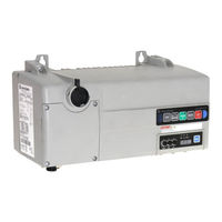
Allen-Bradley ArmorStart 294E User Manual (252 pages)
LT Distributed Motor Controller
Brand:
Allen-Bradley
| Category:
Controller
| Size: 9.41 MB
Table of Contents
Important User Information
2
General Precautions
3
Additional Resources
4
Software Requirements
4
Installation Assistance
5
Rockwell Automation Support
5
New Product Satisfaction Return
6
New and Updated Information
7
Summary of Changes
7
European Communities (EC) Directive Compliance
9
Low Voltage and EMC Directives
9
Preface
9
Introduction
10
Table of Contents
11
Chapter 1
17
Description
17
Product Overview
17
Features
18
Feature Description
19
Standard Features Across Product Family
19
Network Options
20
Factory-Installed Options
22
Armorstart LT Characteristics
23
Catalog Number Explanation
24
Armorstart LT Characteristics
25
Catalog Number Explanation
26
Basic Operation
27
Group Motor Installations for USA and Canada Markets
27
Control Circuit
27
Motor Circuit
29
Local I/O
29
Overload Protection
30
Mode of Operation Bulletin 290E/291E
30
Full-Voltage Start
30
Mode of Operation Bulletin 294E
31
Sensorless Vector Performance
31
Status Leds and Reset
32
Electronic Data Sheet (EDS)
33
Fault Diagnostics
34
Protection Faults
34
Optional HOA Keypad Configuration (Bulletin 290E/291E Only)
35
Optional HOA Selector Keypad
35
Keypad Local Control
35
Optional HOA Selector Keypad
37
With Jog Function (Bulletin 294E Only)
37
Keypad Disable Parameter
38
Source Brake Contactor and Connector (Bulletin 294E Only)
38
Chapter 2
39
Inspecting
39
Installation and Wiring
39
Receiving
39
Storing
39
Unpacking
39
Dimensions
40
Installation Precautions
40
Precautions for Bulletin 290E/291E Applications
40
Precautions for Bulletin 294E Applications
40
Connection Locations
43
Wiring Terminal Detail
44
Branch Circuit Protection
46
Typical System Example
47
Armorconnect Media
48
Armorconnect Cable Ratings
49
Branch Circuit Protection Requirements for Armorconnect
49
Three-Phase Power Media
49
Fusing
50
Electrical Wiring
50
Group Motor Installations for USA and Canada Markets
55
Wiring
55
Cable Workmanship Guidelines
55
Service Space
56
Hand Operation (HOA) Considerations
56
General Wiring Considerations
56
Grounding
57
Grounding Safety Grounds
57
Grounding PE or Ground
57
Grounding Motors
57
AC Line Voltage
58
Line Reactor
58
Power Distribution
58
Delta/Wye with Grounded Wye Neutral
58
Bulletin 294 Motor Cable Considerations
59
Unshielded Cable
59
Shielded Cable
60
Recommended Cable Connectors/Glands
60
Recommended Cord Grips
61
Shield Terminating Connectors
61
Electromagnetic Compatibility (EMC)
62
General Notes (Bulletin 294E Only)
62
Ethernet, Devicenet, and I/O Connections
63
Devicenet Connector (M18)
63
Armorconnect Power Media Receptacles
64
Rockwell Automation Publication 290E-UM001B-EN-P - June
64
Optional Locking Clip
65
Product Commissioning
67
Configuring Ethernet/Ip Address
68
Manually Configure the Network Address Switches
68
Static Address Alternative
69
Using the Rockwell Automation Bootp/Dhcp Utility
70
Save the Relation List
72
Embedded Web Server
74
Network Configuration
75
Parameter Configuration
76
E-Mail Notification Configuration
76
How to Add a New Module Using the Add-On Profile
78
Electronic Keying
80
Connections
81
Configured by
81
HOA Keypad Option
82
Source Brake, Electro-Mechanical Brake Option
82
User Configurable I/O
82
Rslogix 5000 Add-On Profile
83
Auto-Generated Tags
85
Basic Setup Parameters
99
Parameter Groups
100
Chapter 3 IP Address
67
Gateway Address
67
Subnet Mask
67
Chapter 4
99
Electronic Data Sheet (EDS)
99
Armorstart LT Ethernet/Ip Parameters
102
Introduction
102
Parameter Programming
102
Bulletin 290E/291E
102
Basic Status Group
102
Trip Status Group
107
Basic Configuration Group
111
Starter Protection Group
112
User I/O Configuration Group
115
Miscellaneous Configuration Group
119
Advanced Configuration
121
Bulletin 294E
124
Basic Status Group
124
Trip Status Group
129
Motor and Control Group
133
Speed Control Group
135
Starter Protection Group
138
User I/O Configuration Group
140
Miscellaneous Configuration Group
145
Advanced Configuration
146
Bulletin 290E/291E/294E Programmable Parameters
99
Chapter 5
157
Overview
157
Status Leds and Reset
157
Fault Diagnostics
158
Protection Faults
158
Quick Reference Troubleshooting
160
Fault LED Indications
161
Bulletin 290E/291E Faults
161
Bulletin 294E Faults
163
Chapter 6 Bulletin 290E/291E
165
Motor Overload Trip Curves
170
Bulletin 100-K/104-K Life-Load Curves
171
Bulletin 294E
172
Motor Overload Trip Curves
178
Introduction
179
Appendix A
180
Armorstart LT Product Family
180
Installation - General
181
Multiple-Motor Branch Circuits and Motor Controllers Listed for Group
181
And 7.2.10.4(2)
183
Complete Text
183
Maximum Fuse Ampere Rating According to
183
Explanatory Example
185
Combined Load Conductors (C)
191
Controllers (A)
191
Input and Output Conductors of Bulletin 290E and 291E
191
Input and Output Conductors of Bulletin 294E Controllers (B)
191
Appendix B High Level Product Description
193
Product Codes and Name Strings
193
CIP Explicit Connection Behavior
194
EDS Files
194
CIP Object Requirements
194
Identity Object
195
CLASS CODE 0X0001
195
Assembly Object
196
CLASS CODE 0X0004
196
Rockwell Automation Publication 290E-UM001B-EN-P - June
196
I/O Assemblies
197
Message Router
196
CLASS CODE 0X0002
196
Connection Manager Object
203
CLASS CODE 0X0006
203
Class 1 Connections
204
Class 3 Connections
205
Discrete Input Point Object
206
CLASS CODE 0X0008
206
Discrete Output Point Object
206
CLASS CODE 0X0009
206
Discrete Output Point Object Special Requirements
207
Analog Input Point Object
211
CLASS CODE 0X000A
211
(Implemented in Bulletin 294E Units Only)
211
Analog Output Point Object
211
CLASS CODE 0X000B
211
Parameter Object
212
CLASS CODE 0X000F
212
Parameter Group Object
213
CLASS CODE 0X0010
213
Discrete Input Group Object
214
CLASS CODE 0X001D
214
Discrete Output Group Object
214
CLASS CODE 0X001E
214
Control Supervisor Object
215
CLASS CODE 0X0029
215
Overload Object
216
CLASS CODE 0X002C
216
Device Level Ring (DLR) Object
217
CLASS CODE 0X0047
217
Extended Device Object
217
CLASS CODE 0X0064
217
DPI Fault Object
218
CLASS CODE 0X0097
218
DPI Alarm Object
222
CLASS CODE 0X0098
222
TCP/IP Interface Object
223
CLASS CODE 0X00F5
223
Ethernet Link Object
224
CLASS CODE 0X00F6
224
Trip and Warning Email Object
226
CLASS CODE 0X0376
226
Appendix C
229
Introduction
229
Using Devicelogix
229
Devicelogix Programming
230
Devicelogix Programming Example
230
Armorstart LT Bulletin 294E Example Configuration
236
Download the AOP
237
Use of the AOP in Rslogix 5000
242
Advertisement
Advertisement
Related Products
Allen-Bradley ArmorStart 290E
Allen-Bradley ArmorStart 291E
Allen-Bradley 2080-OW4I
Allen-Bradley 2080-TC2
Allen-Bradley 2080-DNET20
Allen-Bradley 2080-LC20-20QBB
Allen-Bradley 20F
Allen-Bradley PowerFlex 20-750-20COMM-F1
Allen-Bradley 2080-LC50-48QWB
Allen-Bradley 22A-V1P5N104
Allen-Bradley Categories
Control Unit
Controller
I/O Systems
Power Supply
Switch
More Allen-Bradley Manuals
Login
Sign In
OR
Sign in with Facebook
Sign in with Google
Upload manual
Upload from disk
Upload from URL