Sign In
Upload
Manuals
Brands
Airoptic Manuals
Industrial Equipment
GasEye
Airoptic GasEye Manuals
Manuals and User Guides for Airoptic GasEye. We have
1
Airoptic GasEye manual available for free PDF download: User Manual
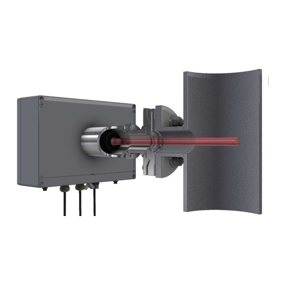
Airoptic GasEye User Manual (254 pages)
Cross Duct SG and MG
Brand:
Airoptic
| Category:
Industrial Equipment
| Size: 37 MB
Table of Contents
Table of Contents
5
Introduction
9
General Information
9
Warranty Conditions
9
Delivery Information
9
Calibration Information
9
General Information about the Analyzer
10
Introduction
10
Types of Applications
10
Analyzer Arrangement
11
Gaseye Cross Duct Sg Mechanical Assembly
11
Gaseye Cross Duct Multi Gas (Mg) Mechanical Assembly
13
Functional Description
15
Principle of Operation
15
Technical Data
15
Design, Enclosure
15
Electrical Characteristics
17
Dynamic Performance
17
Electric Inputs and Outputs
17
Customer Interface
18
Climatic Conditions
18
Purging
18
Packaging
19
Calibration and Calibration Certificate
20
Installation
22
Safety Information
22
Mounting
23
Mounting Conditions
23
Preparations
23
Optical Path Length Determination
24
Purging Tubes
25
Flange Installation (3° or 1° Wedge Window Standard Version)
26
Flange Installation (1° Wedge Window Easy-To-Clean Version "Etc")
28
Alignment of Gaseye Cross Duct
31
Alignment Kit
31
Alignment Procedure
33
Sensor Mounting
39
Housing Lid Opening
42
Electrical Installation
45
Electrical Connections
45
Gaseye Cross Duct Single Gas
46
Gaseye Cross Duct Multi Gas
47
Gaseye Cross Duct Multi Gas Multi Point
48
Central Unit - Electrical Terminals
48
Power Supply
52
Analog Outputs and Inputs
53
Active Analog Outputs
55
Passive Analog Outputs
56
Active Analog Inputs
57
Passive Analog Inputs
58
Dout
59
Din
60
Rtd
61
Loop (Hybrid) Cable Connection
64
Receiver Unit - Loop Cable Installation Instruction
65
Central Unit - Loop Cable Installation Instruction
71
Customer Cable Connection
73
Customer Cable Installation Instruction
73
Ethernet Connection
77
Ethernet Cable Installation Instruction
78
Ethernet Cable Installation Instruction (Atex Version)
79
Industrial Protocols Connection
81
Modbus Rtu (Rs485)
81
Modbus Tcp
117
Profinet
117
Add-On Module
117
Startup Procedure
121
Hmi - Front Panel Display
122
Overview
122
Menu
123
Settings
124
Diagnostic
125
Measurements
126
Analog Input
129
Analog Output
130
Signals
131
Buttons
131
Editing Parameters
132
Editing Network Settings
134
Editing Ain/Aout Scaling
135
Webserver Application
137
Establishing Communication with the Instrument
137
User Access Level
141
Measurement Tab
143
Show Table
144
Show Grid
145
Show Plot
146
Settings
147
Measurement Groups
148
8.3.3.1. MP1 -> Process
148
8.3.3.2. MP1 -> Concentration
149
8.3.3.3. MP1 -> Laser
149
8.3.3.4. TEC -> Tec0
150
8.3.3.5. TEC -> Tec1
150
8.3.3.6. TEC -> Tec2
151
8.3.3.7. TEC -> Tec3
151
8.3.3.8. System -> System
152
Io -> Aout (Analog Output Measurement)
152
Io -> Ain (Analog Input Measurement)
153
Io -> Digitalinout
154
Parameters Tab
156
Parameter Groups
158
Mp1 -> Process (Process Environment Configuration)
158
8.4.1.2. MP1 -> Gas101
160
8.4.1.3. MP1 -> Gas102
161
8.4.1.4. MP1 -> Gas103
162
8.4.1.5. MP1 -> Gas104
163
8.4.1.6. MP1 -> Gas105
164
8.4.1.7. MP1 -> Gas106
165
8.4.1.8. MP1 -> Gas107
166
8.4.1.9. MP1 -> Gas108
167
Mp1 -> Temp
168
Io -> Dout (Digital Output Operating Mode Configuration)
169
Io -> Aout (Analog Output Configuration)
171
Io -> Ain (Analog Input Configuration)
175
Io -> Rtd (Resistance Temperature Sensor Configuration)
177
Io -> Amb_Press (Ambient Pressure Sensor Configuration)
178
Network -> Net (Service Ethernet Port Configuration)
179
Network -> Modbusrtu (Modbus Slave Transmission Configuration)
180
Network -> Datarange
181
System -> Rtc (Real Time Clock Configuration)
183
System -> Hmi (Human-Machine Interface Configuration)
183
System -> Alarm
184
Settings Tab
189
Factory Config Tab
191
About Tab
191
Purging (Non-Atex)
192
Housing Purging (Optional)
193
Single Gas
193
Multi Gas
194
Tube and Process Purging
198
Atex (Zone 1 and 21 Purging System Installation)
201
Basic Requirements and Safe Use
201
Atex Marking
203
Special Conditions for Safe Use
203
Overview of Zone 1 and 21 Purging System for Gaseye Cross Duct Single Gas
204
Overview of Zone 1 and 21 Purging System for Gaseye Cross Duct Multi Gas
206
Technical Parameters
208
Zone 1/21 Purging System
209
Zone 1 and 21 Purging System Installation with Gaseye Cross Duct Single Gas
209
Zone 1 and 21 Purging System Installation with Gaseye Cross Duct Multi Gas
216
Differences between Single Gas and Multi Gas Systems
221
Zone 1 and 21 Purging System Enclosures Mounting
222
Zone 1 and 21 Purging System Adjustment Possibilities
224
System Pressurization Failure Alarm
225
System Electrical Connections - Intrinsic Safety Warnings
226
System Conservation for Zone 1 and 21
227
Contact Information
227
Iecex (Zone 2 and 22 Purging System Installation)
228
Basic Requirements and Safe Use
228
Iecex Marking
230
Special Conditions for Safe Use
230
Overview of Zone 2 and 22 Purging System for Gaseye Cross Duct Single Gas
231
Overview of Zone 2 and 22 Purging System of Gaseye Cross Duct Multi Gas
234
Technical Parameters
236
Zone 2 and 22 Purging System Installation with Gaseye Cross-Duct Single Gas
237
Zone 2 and 22 Purging System Installation with Gaseye Cross-Duct Multi Gas
240
Differences between Single Gas and Multi Gas Systems
243
Zone 2 and 22 Purging System Enclosures Mounting
243
Zone 2 and 22 Purging System Adjustment Possibilities
246
System Pressurization Failure Alarm
247
System Electrical Connections - Intrinsic Safety Warnings
248
System Conservation for Zone 2 and 22
249
Troubleshooting
250
Appendix 1. Parameters List
251
Appendix 2. Measurements List
254
Advertisement
Advertisement
Related Products
Airoptic GasEye Extractive
Airoptic Categories
Measuring Instruments
Industrial Equipment
More Airoptic Manuals
Login
Sign In
OR
Sign in with Facebook
Sign in with Google
Upload manual
Upload from disk
Upload from URL