Table of Contents
Advertisement
Quick Links
Advertisement
Table of Contents

Summary of Contents for Airoptic GasEye
- Page 2 Introduction GasEye Cross Duct SG and MG Operating instructions, 05/2021...
- Page 3 Introduction GasEye Cross Duct SG and MG Manufacturer: Airoptic Sp. z o.o. Address: Ul. Rubiez 46B, 61-612 Poznan, Poland Telephone number: +48 61 6272 128 E-mail address: info@airoptic.pl Web address: www.airoptic.pl Product Information: Gas analyzer Application: In-situ analyzer Brand name:...
- Page 4 Introduction GasEye Cross Duct SG and MG Operating instructions, 05/2021...
-
Page 5: Table Of Contents
TYPES OF APPLICATIONS ........................10 ANALYZER ARRANGEMENT ......................... 11 GASEYE CROSS DUCT SG MECHANICAL ASSEMBLY ................11 GASEYE CROSS DUCT MULTI GAS (MG) MECHANICAL ASSEMBLY ............13 FUNCTIONAL DESCRIPTION ......................... 15 PRINCIPLE OF OPERATION ........................15 TECHNICAL DATA ..........................15 DESIGN, ENCLOSURE ........................... - Page 6 MP1 -> GAS106 ........................165 8.4.1.8. MP1 -> GAS107 ........................166 8.4.1.9. MP1 -> GAS108 ........................167 8.4.1.10. MP1 -> TEMP ........................... 168 8.4.1.11. IO -> DOUT (DIGITAL OUTPUT OPERATING MODE CONFIGURATION) ........169 GasEye Cross Duct SG and MG Operating instructions, 05/2021...
- Page 7 ATEX MARKING ..........................203 SPECIAL CONDITIONS FOR SAFE USE ....................203 OVERVIEW OF ZONE 1 AND 21 PURGING SYSTEM FOR GASEYE CROSS DUCT SINGLE GAS ....204 OVERVIEW OF ZONE 1 AND 21 PURGING SYSTEM FOR GASEYE CROSS DUCT MULTI GAS ....206 TECHNICAL PARAMETERS........................
- Page 8 Introduction GasEye Cross Duct SG and MG Operating instructions, 05/2021...
-
Page 9: Introduction
Calibration information The GasEye Cross Duct system is factory calibrated using certified gas mixtures. The instrument utilizes an internal in-line reference gas cell for real time verification of the calibration status or a process gas normally present in the process gas stream. -
Page 10: General Information About The Analyzer
General information about the analyzer Introduction The laser based GasEye Cross Duct spectrometer is a versatile analyzing tool for industrial process applications. It can be configured to operate in the near-infrared (NIR), mid-infrared (MIR) and infrared (IR) wavelength range thereby covering the majority of all gases of interest in the industrial process monitoring. -
Page 11: Analyzer Arrangement
(included). The GasEye Cross Duct utilizes an internal in-line reference gas cell or a process gas (e.g. H2O) for real time verification of the calibration status. - Page 12 Receiver front panel White LED Cable gland PG21 Cable gland M20 HMI button HMI front panel HMI green LED HMI red LED HMI window Table 2. Descriptions of receiver and transmitter unit. GasEye Cross Duct SG and MG Operating instructions, 05/2021...
-
Page 13: Gaseye Cross Duct Multi Gas (Mg) Mechanical Assembly
General information about the analyzer GasEye Cross Duct Multi Gas (MG) mechanical assembly The GasEye Cross Duct MG (Multi Gas) analyzer consists of a pair of cross-duct sensors - a transmitter and a receiver unit as well as a central unit. The transmitter unit emits laser radiation directly through the process containing the constituents of interest. - Page 14 Cable gland M25 Cable gland PG21 Cable gland M20 HMI button HMI green LED HMI red LED HMI front panel HMI window Table 4. Descriptions of receiver, transmitter, and central unit housing assembly. GasEye Cross Duct SG and MG Operating instructions, 05/2021...
-
Page 15: Functional Description
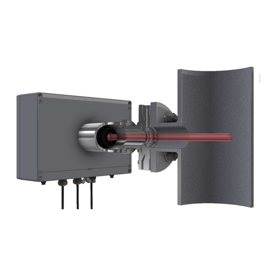
Functional description Principle of operation GasEye Cross Duct is a laser analyzer that utilizes tunable diode laser (TDL) absorption spectroscopy. The central unit sends a laser light through the process which is detected by the receiver unit mounted on the opposite side of the process. - Page 16 Technical data Transmitter unit: 15 kg Figure 6. GasEye Cross Duct Single Gas overview. MULTI GAS Transmitter: Width x height: 230 mm x 202 mm Length: 350 mm Receiver: Width x height: 160 mm x 160 mm Length: 330 mm...
-
Page 17: Electrical Characteristics
Technical data Figure 7. GasEye Cross Duct Multi Gas overview. Electrical characteristics Power input: 24 VDC nominal (19-30 VDC) Power consumption: < 15VA (single gas) < 25VA (multi gas) EMC immunity: In accordance with EN 61326-1 Electric safety: In accordance with 61010-1 Dynamic performance Warm-up time: approx. -
Page 18: Customer Interface
8 x digital output (isolated) WARNING Analog outputs GasEye Cross Duct may have active or passive analog outputs, depending on the customer requirement. Please ensure that the outputs are handled according to their type. For details, please refer to Chapter 5 of this manual. -
Page 19: Packaging
Flange screws, nuts and washers Ethernet cable (used for analyzer-to-computer connection) Documents: Packing list Calibration certificate Analyzer test report Process flange certificates Tools: Wrench size 24 Hex 6 mm Hex 14 mm Flat-head screwdriver (for electrical connections) GasEye Cross Duct Operating instructions, 05/2021... -
Page 20: Calibration And Calibration Certificate
(LOD) which determines the lowest measurable concentration. This quantity is estimated for each application and is determined for each device before shipping to our customers. For every GasEYE analyzer we determine the limit of detection during a 12-hour cycle in a climate chamber. - Page 21 Technical data Figure 8. Calibration certificate. GasEye Cross Duct Operating instructions, 05/2021...
-
Page 22: Installation
Installation Safety information GasEye Cross Duct is classified as a Class 1 laser product. The emitted laser radiation is invisible (near infrared) and not hazardous to an unprotected eye. GasEye Cross Duct has warning labels placed at positions specified in the EN 60825-1:2014- 11 norm. -
Page 23: Mounting
If the unit is exposed to direct solar radiation, ensure that the total temperature will not exceed the maximum permitted temperature. If these conditions cannot be fulfilled the GasEye Cross Duct must be installed in a cabinet with a controlled environment. -
Page 24: Optical Path Length Determination
During the installation of the GasEye Cross Duct instrument, the laser and the photodetector must be aligned to the optical axis of the sensor pair. Note that each sensor has an optical axis of its own which is its axis of symmetry. -
Page 25: Purging Tubes
Please refer to Figure 11 for installation details. Figure 11. Schematic drawing of purging tube installation. Name Nuts Washers Process interface Graphite gasket Purging tube Alignment flange Screws Table 5. Descriptions of purging tube installation. GasEye Cross Duct Operating instructions, 05/2021... -
Page 26: Flange Installation (3° Or 1° Wedge Window Standard Version)
Some isopropyl alcohol may also be used. Figure 13. Flange with window. GasEye Cross Duct SG and MG Operating instructions, 05/2021... - Page 27 4. Screw on M16 nuts with pads and tighten them with 14mm hex key and 24mm wrench. Nuts should be tightened with similar torque (around 60- 70Nm) to ensure good sealing on the gaskets. Figure 15. Nuts mounting. GasEye Cross Duct Operating instructions, 05/2021...
-
Page 28: Flange Installation (1° Wedge Window Easy-To-Clean Version "Etc")
Some isopropyl alcohol may also be used. Figure 17. ETC - Flange with window. GasEye Cross Duct SG and MG Operating instructions, 05/2021... - Page 29 4. Screw on M12 nuts with pads and tighten them with 8mm hex key and 19mm wrench. Nuts should be tightened with similar torque (around 60-70Nm) to nsure good sealing on the gaskets. Figure 19. ETC - Nuts mounting. GasEye Cross Duct Operating instructions, 05/2021...
- Page 30 Figure 20. Mounting ETC adapter. 6. Tighten the clamp ring (ᴓ 90mm) on the adapter rim. Figure 21. ETC clamp ring. GasEye Cross Duct SG and MG Operating instructions, 05/2021...
-
Page 31: Alignment Of Gaseye Cross Duct
Installation Alignment of GasEye Cross Duct The transmitter and receiver units must be aligned using two adjustment screws. These screws enable to regulate the axis of symmetry of the transmitter and receiver units and ensure that the laser beam travels properly between them. The receiver/transmitter units are mounted on flanges that have a spherical surface (See figure below) that helps in the alignment procedure. - Page 32 3. Coarse alignment tool 4. Allen key for adjustment screws (6 mm size) 5. Batteries for LED torch (3xAAA) and dry grease for flange adapter gasket 6. Spare flange adapter gasket 7. Clamp ring GasEye Cross Duct SG and MG Operating instructions, 05/2021...
-
Page 33: Alignment Procedure
1. Place the light source in the sleeve and switch it on. Make sure that the light source is operational. Figure 24. Placing the light source. 2. Proceed to the transmitter side of the instrument. GasEye Cross Duct Operating instructions, 05/2021... - Page 34 (on the side of the flange). Figure 26. Aiming piece positioning. GasEye Cross Duct SG and MG Operating instructions, 05/2021...
- Page 35 Installation 5. Tighten the clamp ring on the aiming piece rim. Figure 27. Clamp ring tightening. 6. Place coarse aligning unit inside of the aiming piece base. Figure 28. Coarse aligning unit. GasEye Cross Duct Operating instructions, 05/2021...
- Page 36 8. By sliding the coarse aligning unit the bright spot may be focused on screen. Find position at which the spot becomes the smallest and sharpest. Figure 30. Finding the best spot. GasEye Cross Duct SG and MG Operating instructions, 05/2021...
- Page 37 Make sure that crosshair oriented just like in the picture (in line with the aiming tool screw and the purging inlet in flange). Figure 32. Crosshair orientation. GasEye Cross Duct Operating instructions, 05/2021...
- Page 38 (both transmitter/central unit or CORRECT INCORRECT receiver – picture below) Figure 33. Finding the optimal aligning point. Figure 34. Target aligning point sticker (on the bottom of receiver unit lid). GasEye Cross Duct SG and MG Operating instructions, 05/2021...
-
Page 39: Sensor Mounting
Figure 35. Mounting the receiver on the flange. 3. Make sure the receiver tube is connected properly so the front surface of the tube is aligned to the alignment flange sleeve surface. The connection can be tightened now. GasEye Cross Duct Operating instructions, 05/2021... - Page 40 Installation Figure 36. The receiver-flange connection. 4. To tighten the connection place the clamp on the rim of the tube. Figure 37. Placing the clamp. GasEye Cross Duct SG and MG Operating instructions, 05/2021...
- Page 41 5. Tighten the connection using the clamp screw. Figure 38. Connection with the clamp screw. 6. Mount the transmitter. Follow the same procedure as for the receiver. 7. The system is now prepared for electrical connections. GasEye Cross Duct Operating instructions, 05/2021...
-
Page 42: Housing Lid Opening
Please do it carefully since the lid has connection to boards inside the housing. 2. Separate the lid out of the housing, until the end of wire hinges. Keep horizontal direction (perpendicularly to front side). Figure 39. Central unit housing lid bolts GasEye Cross Duct SG and MG Operating instructions, 05/2021... - Page 43 3. Tilt the lid at an angle (maximally 110°) to allow easy access to the components inside the housing. Tilt the lid carefully, do not use too much strength Figure 40. Central unit lid opening. Figure 41. Maximum angle of central unit lid opening. GasEye Cross Duct Operating instructions, 05/2021...
- Page 44 1. Cautiously dismount housing lid by unscrewing each of the four bolts. Do it carefully because receiver unit lid is not attached to the rest of the unit by any other way than the bolts. Figure 43. Transmitter unit lid bolts. GasEye Cross Duct SG and MG Operating instructions, 05/2021...
-
Page 45: Electrical Installation
Electrical installation Electrical connections The GasEye Cross Duct gas analyzer consists of a cross-duct sensors - a central/transmitter unit and a receiver unit. The transmitter unit emits laser radiation directly through the process containing the constituents of interest. The receiver unit collects the radiation on the other side of the process duct. -
Page 46: Gaseye Cross Duct Single Gas
WebServer. Additional cables for industrial protocols must be provided by the customer. GasEye Cross Duct Single Gas GasEye Cross Duct Single Gas consists of central unit and receiver unit. See figure below. Figure 44. Cross Duct Single Gas electrical connection diagram. -
Page 47: Gaseye Cross Duct Multi Gas
Electrical installation GasEye Cross Duct Multi Gas GasEye Cross Duct Multi Gas consists of transmitter unit, central unit and receiver unit. See figure below. Figure 45. Cross Duct Multi Gas electrical connection diagram. GasEye Cross Duct Operating instructions, 05/2021... -
Page 48: Gaseye Cross Duct Multi Gas Multi Point
Electrical installation GasEye Cross Duct Multi Gas Multi Point The system is composed of two transmitter units, one central unit and two receiver units. See figure below. Figure 46. Cross Duct Gas Multi Point Electrical Connection diagram. Central unit – electrical terminals The description of the central unit electrical terminals with its functionalities is presented in this chapter. - Page 49 Electrical installation Figure 47. Top view of the HOST board Figure 48. Electrical terminals numbering. GasEye Cross Duct Operating instructions, 05/2021...
- Page 50 Electrical installation Figure 49. Electrical terminal configuration. GasEye Cross Duct SG and MG Operating instructions, 05/2021...
- Page 51 1÷8 30VDC, 0.5A Isolated DOUT_NAMUR Digital outputs DOUT_PWR supply voltage Digital inputs DIGITAL INPUTs 1÷8 30VDC, 0.1A Isolated Digital inputs DIN_PWR supply voltage MODBUS RTU RS485 Isolated Table 6. Description of the electrical terminals GasEye Cross Duct Operating instructions, 05/2021...
-
Page 52: Power Supply
(14AWG). Connect the positive pole of the power supply to the pin 25 and negative pole to the pin 26. Power supply connection diagram is presented at Figure 50. Figure 50. Power supply connection diagram. GasEye Cross Duct SG and MG Operating instructions, 05/2021... -
Page 53: Analog Outputs And Inputs
P (Passive). To set analog input or analog output signal to active change assigned switch position on position A (Active). Figure 51. Analog input/output dip switches. GasEye Cross Duct Operating instructions, 05/2021... - Page 54 Analog outputs can operate in two modes accordingly to NAMUR NE43 and EN 15267-3:2008. The operation mode can be selected via WebServer in Parameters/AOUT tab. GasEYE device is generated the failure signal at the level of 3.3 mA. NAMUR NE43 is an international association of process instrumentation user companies that have worked on improving the diagnostic coverage in 4 to 20-mA analog output transmitters to address associated safety issues (Figure 52).
-
Page 55: Active Analog Outputs
LOAD WARNING Active analog outputs GasEye Cross Duct provides supply voltage for the active analog outputs and thus analog outputs MUST NOT BE powered externally. Please set the dip switch to Active (A) before powering up the system. GasEye Cross Duct... -
Page 56: Passive Analog Outputs
LOAD WARNING Passive analog outputs GasEye Cross Duct does not provide supply voltage for the passive analog outputs, thus they MUST BE powered externally. Please set the dip switch to Passive (P) before powering up the system. GasEye Cross Duct SG and MG... -
Page 57: Active Analog Inputs
Figure 56. Exemplary usage of active analog input. WARNING Active analog inputs GasEye Cross Duct provides supply voltage for the active analog inputs and thus analog inputs MUST NOT BE powered externally. Please set the dip switch to Active (A) before powering up the system. -
Page 58: Passive Analog Inputs
Figure 57. Exemplary usage of passive analog input. WARNING Passive analog inputs GasEye Cross Duct does not provide supply voltage for the passive analog inputs, thus they MUST BE powered externally. Please set the dip switch to Passive (P) before powering up the system. -
Page 59: Dout
(green LED -> Power OK, red LED -> Power NOT OK) can be found. Figure 58. Exemplary usage of digital output. WARNING Digital outputs GasEye Cross Duct does not provide supply voltage for the digital outputs, thus they MUST BE powered externally. GasEye Cross Duct Operating instructions, 05/2021... -
Page 60: Din
LED -> Power OK, red LED -> Power NOT OK) can be found. Figure 59. Exemplary usage of digital input. WARNING Digital inputs GasEye Cross Duct does not provide supply voltage for the digital inputs, thus they MUST BE powered externally. GasEye Cross Duct SG and MG Operating instructions, 05/2021... -
Page 61: Rtd
Electrical installation GasEye system provides the resistance temperature detectors (RTDs) input for measuring the process temperature. The system can be configured with two dip switches to operate with PT100/PT1000 and 2-,3-,4-wire connection. Please refer Figure 60 to Figure 62 for signal connection. - Page 62 Electrical installation Figure 61. Exemplary usage of 3-wire RTD. WARNING 3-wire RTD require additional terminal connection, please make the external jumper for 36 and 35. GasEye Cross Duct SG and MG Operating instructions, 05/2021...
- Page 63 Electrical installation Figure 62. Exemplary usage of 4-wire RTD. GasEye Cross Duct Operating instructions, 05/2021...
-
Page 64: Loop (Hybrid) Cable Connection
(2x0.5mm ). For proper operation use only the loop cable supplied by Airoptic. Please refer to Figure 64 for electrical signals connection. Please follow the step-by-step instruction for correct installation. Fiber cable (SMA connector) Power supply (+) Power supply (–) -
Page 65: Receiver Unit - Loop Cable Installation Instruction
Figure 65. Hybrid loop cable details. 3. Place the sealing nut and the claw on the hybrid loop cable. Sealing nut Claw EMC contact Figure 66. Hybrid loop cable – sealing nut and claw. GasEye Cross Duct Operating instructions, 05/2021... - Page 66 Electrical installation 4. Ensure that the EMC contact is placed on the aluminum sleeve. Figure 67. Hybrid loop cable – EMC contact. GasEye Cross Duct SG and MG Operating instructions, 05/2021...
- Page 67 Electrical installation Figure 68. Grounding point for hybrid loop cable (stainless steel glands version) GasEye Cross Duct Operating instructions, 05/2021...
- Page 68 EMC contact placed inside the gland. 5. After opening of the receiver side of the instrument you will see the following board. Fiber cable receptacle Receiver power supply Figure 70. Hybrid loop cable installation. GasEye Cross Duct SG and MG Operating instructions, 05/2021...
- Page 69 Green –> ( - ) 10. When the installation is completed the assembly should look like on the following figure. Close the receiver unit with the lid. Figure 71. Completed hybrid loop cable installation (nickel-plated brass glands version). GasEye Cross Duct Operating instructions, 05/2021...
- Page 70 Electrical installation Figure 72. Completed hybrid loop cable installation (stainless steel glands version). GasEye Cross Duct SG and MG Operating instructions, 05/2021...
-
Page 71: Central Unit - Loop Cable Installation Instruction
3. Place the other two wires from the hybrid loop cable in the ports of the terminal: c. Brown –> 1 d. Green –> 2 Figure 74. Placing wires from the hybrid loop cable in the terminal. GasEye Cross Duct Operating instructions, 05/2021... - Page 72 Electrical installation 4. When the installation is completed the assembly should look like on the following figure. Figure 75. Completed assembly. Figure 76. Fiber cable connector grounding (stainless steel glands version). GasEye Cross Duct SG and MG Operating instructions, 05/2021...
-
Page 73: Customer Cable Connection
Please use the cable with minimum 12 x 0.5mm wires and external diameter between 7-12 mm to fit into the gland. Cable supplied by Airoptic is preferred. Please follow the step-by-step instruction for correct installation. Figure 77. Customer cable. - Page 74 3. Ensure that the EMC contact is placed on the aluminum sleeve Figure 79. EMC contact. In case of stainless steel glands version of the analyzer, please mount the customer cable in similar way as on the Figure 76. GasEye Cross Duct SG and MG Operating instructions, 05/2021...
- Page 75 5. Using the wrench (size 24) tighten the connection. The customer cable should now be blocked in the gland. 6. Place the PE wire (green-yellow) under the wing nut and tighten it. Figure 81. PE wire. GasEye Cross Duct Operating instructions, 05/2021...
- Page 76 Figure 82. Powering the analyzer. 8. Place other wires in proper sockets for connection with analog and digital inputs/outputs as desired for specific application of the analyzer. Figure 83. Connection with analog and digital inputs/outputs. GasEye Cross Duct SG and MG Operating instructions, 05/2021...
-
Page 77: Ethernet Connection
A separate ethernet cable is connected via special gland for communication with the analyzer via webserver. To ensure IP65 use only the ethernet cable supplied by Airoptic. Please follow the step-by-step instruction for correct installation. Figure 84. Ethernet cable. GasEye Cross Duct... -
Page 78: Ethernet Cable Installation Instruction
Electrical installation Ethernet cable installation instruction: 1. Unscrew ethernet gland cap. Figure 85. Ethernet gland opening. 2. Put ethernet cable in the gland and twist the nut. Figure 86. Ethernet gland connection. GasEye Cross Duct SG and MG Operating instructions, 05/2021... -
Page 79: Ethernet Cable Installation Instruction (Atex Version)
Ethernet cable installation instruction (ATEX version): 1. Overview of ethernet cable for ATEX version of analyzer: Figure 88. Ethernet cable (ATEX version). 2. Put the cable through the gland and connect plug into ethernet socket. GasEye Cross Duct Operating instructions, 05/2021... - Page 80 3. Place claw and nut in the gland and twist the nut. Make sure the nut is tightened and the cable is not moving in the gland. Figure 90. Ethernet cable connection through sealed gland. GasEye Cross Duct SG and MG Operating instructions, 05/2021...
-
Page 81: Industrial Protocols Connection
Electrical installation Industrial protocols connection The GasEye Cross Duct gas analyzer has implemented MODBUS RTU, MODBUS TCP and PROFINET industrial communication protocols. On plant can work only one protocol and it is declared by customer during ordering. Thanks to integrated analyzer... - Page 82 16 -bits of floating point value (first part) 0x0A Gas concentration 16 -bits of floating point value (second part) GAS103.CONCENTRATION 0x0B Gas concentration 16 -bits of floating point value (first part) GAS104.CONCENTRATION 0x0C Gas concentration GasEye Cross Duct SG and MG Operating instructions, 05/2021...
- Page 83 Gas concentration Scaling to integer value (0 - 27648) GAS105.CONSIM 0x1A Gas concentration Scaling to integer value (0 - 27648) GAS106.CONSIM 0x1B Gas concentration Scaling to integer value (0 - 27648) GAS107.CONSIM 0x1C Gas concentration GasEye Cross Duct Operating instructions, 05/2021...
- Page 84 16 -bits of floating point value (second part) FIBER1.TRANSMISSION 0x2B Fiber transmission 16 -bits of floating point value (first part) 0x2C Fiber transmission 16 -bits of floating point value (second part) FIBER2.TRANSMISSION 0x2D Fiber transmission GasEye Cross Duct SG and MG Operating instructions, 05/2021...
- Page 85 16 -bits of floating point value (second part) TEC0.THL_REF_AMP 0x3B Laser amplitude reference 16 -bits of floating point value (first part) 0x3C Laser temperature conditions 16 -bits of floating point value TEC0.AMB_TEMPERATURE 0x3D (second part) GasEye Cross Duct Operating instructions, 05/2021...
- Page 86 0 - Low level platform is not working 1 - Device initialization and memory test 2 - Internal communication check Automatic gain control calibration procedure SYSTEM.STARTUP_PROCEDURE 0x4B 4 - Device parameters check and set GasEye Cross Duct SG and MG Operating instructions, 05/2021...
- Page 87 16 -bits of floating point value (second part) AOUT2 0x5F Analog output value 16 -bits of floating point value (first part) 0x60 Analog output value 16 -bits of floating point value (second part) AOUT3 0x61 Analog output value GasEye Cross Duct Operating instructions, 05/2021...
- Page 88 16 -bits of floating point value (first part) 0x70 Analog input scaling value 16 -bits of floating point value (second part) AIN3.VAL 0x71 Analog input scaling value AIN3.VALSIM 0x72 114 Scaling to integer value (0 - 27648) GasEye Cross Duct SG and MG Operating instructions, 05/2021...
- Page 89 127 16 -bits of floating point value (first part) Process temperature manual value 0x80 128 16 -bits of floating point value (second part) Process temperature manual value PROCESS.PRESS_IS 0x81 129 Process pressure input signal selection GasEye Cross Duct Operating instructions, 05/2021...
- Page 90 (second part) Span offset value GAS102.SPAN_CALIBRATION 0x8F 143 16 -bits of floating point value (first part) Span calibration factor 0x90 144 16 -bits of floating point value (second part) Span calibration factor GasEye Cross Duct SG and MG Operating instructions, 05/2021...
- Page 91 158 16 -bits of floating point value (second part) Span offset value GAS106.SPAN_CALIBRATION 0x9F 159 16 -bits of floating point value (first part) Span calibration factor 0xA0 160 16 -bits of floating point value (second part) GasEye Cross Duct Operating instructions, 05/2021...
- Page 92 0xAF 175 Signal selection for digital output DOUT.DO2 0xB0 176 Signal selection for digital output DOUT.DO3 0xB1 177 Signal selection for digital output DOUT.DO4 0xB2 178 Signal selection for digital output GasEye Cross Duct SG and MG Operating instructions, 05/2021...
- Page 93 192 16 -bits of floating point value (second part) Reserved - future use AOUT2.SELECT_SIGNAL 0xC1 193 Measurement signal selection for the output AOUT2.MANUAL_VALUE 0xC2 194 16 -bits of floating point value (first part) Manual mode value in scaling range GasEye Cross Duct Operating instructions, 05/2021...
- Page 94 207 16 -bits of floating point value (first part) Scaling range value corresponds to 4 0xD0 208 16 -bits of floating point value (second part) Scaling range value corresponds to 4 GasEye Cross Duct SG and MG Operating instructions, 05/2021...
- Page 95 20 mA 0xDD 221 16 -bits of floating point value (second part) Scaling range value corresponds to 20 mA AOUT4.A 0xDE 222 16 -bits of floating point value (first part) Reserved - future use GasEye Cross Duct Operating instructions, 05/2021...
- Page 96 (second part) Reserved - future use AIN1.B 0xED 237 16 -bits of floating point value (first part) Reserved - future use 0xEE 238 16 -bits of floating point value (second part) GasEye Cross Duct SG and MG Operating instructions, 05/2021...
- Page 97 Scaling range value corresponds to 20 mA 0xFA 250 16 -bits of floating point value (second part) Scaling range value corresponds to 20 mA AIN3.A 0xFB 251 16 -bits of floating point value (first part) GasEye Cross Duct Operating instructions, 05/2021...
- Page 98 264 16 -bits of floating point value (first part) Const time value put to IIR filter 0x109 265 16 -bits of floating point value (second part) Const time value put to IIR filter GasEye Cross Duct SG and MG Operating instructions, 05/2021...
- Page 99 Alarm threshold value ALARM2.HYSTERESIS 0x120 288 16 -bits of floating point value (first part) Alarm hysteresis value 0x121 289 16 -bits of floating point value (second part) Alarm hysteresis value ALARM3.ENABLE 0x122 290 Alarm enable/disable GasEye Cross Duct Operating instructions, 05/2021...
- Page 100 314 Alarm signal selection ALARM5.OPERATOR 0x13B 315 Alarm mathematical operator ALARM5.THRESHOLD 0x13C 316 16 -bits of floating point value (first part) Alarm threshold value 0x13D 317 16 -bits of floating point value (second part) GasEye Cross Duct SG and MG Operating instructions, 05/2021...
- Page 101 Alarm hysteresis value 0x153 339 16 -bits of floating point value (second part) Alarm hysteresis value ALARM8.ENABLE 0x154 340 Alarm enable/disable ALARM8.AUTORESET_ENABLE 0x155 341 Alarm autoreset enable/disable ALARM8.RESET 0x156 342 Alarm manual reset GasEye Cross Duct Operating instructions, 05/2021...
- Page 102 365 Alarm mathematical operator ALARM10.THRESHOLD 0x16E 366 16 -bits of floating point value (first part) Alarm threshold value 0x16F 367 16 -bits of floating point value (second part) Alarm threshold value GasEye Cross Duct SG and MG Operating instructions, 05/2021...
- Page 103 Process temperature manual value 0x02 2 16 -bits of floating point value (second part) Process temperature manual value PROCESS.PRESS_IS 0x03 3 Process pressure input signal selection PROCESS.PRESS_SENSOR_TYPE 0x04 4 Pressure sensor type selection (absolute/ gauge) GasEye Cross Duct Operating instructions, 05/2021...
- Page 104 Span calibration factor 0x12 18 16 -bits of floating point value (second part) Span calibration factor GAS102.OFFSET 0x13 19 16 -bits of floating point value (first part) Span offset value GasEye Cross Duct SG and MG Operating instructions, 05/2021...
- Page 105 33 16 -bits of floating point value (first part) Span calibration factor 0x22 34 16 -bits of floating point value (second part) Span calibration factor GAS106.OFFSET 0x23 35 16 -bits of floating point value (first part) GasEye Cross Duct Operating instructions, 05/2021...
- Page 106 50 Signal selection for digital output DOUT.DO3 0x33 51 Signal selection for digital output DOUT.DO4 0x34 52 Signal selection for digital output AOUT.FORCE_MANUAL_MODE 0x35 53 Force manual mode for all analog ENABLE outputs GasEye Cross Duct SG and MG Operating instructions, 05/2021...
- Page 107 66 16 -bits of floating point value (second part) Reserved - future use AOUT2.SELECT_SIGNAL 0x43 67 Measurement signal selection for the output AOUT2.MANUAL_VALUE 0x44 68 16 -bits of floating point value (first part) Manual mode value in scaling range GasEye Cross Duct Operating instructions, 05/2021...
- Page 108 80 16 -bits of floating point value (second part) Manual mode value in scaling range AOUT3.SCALE_MIN 0x51 81 16 -bits of floating point value (first part) Scaling range value corresponds to 4 mA GasEye Cross Duct SG and MG Operating instructions, 05/2021...
- Page 109 93 16 -bits of floating point value (second part) Scaling range value corresponds to 4 mA AOUT4.SCALE_MAX 0x5E 94 16 -bits of floating point value (first part) Scaling range value corresponds to 20 mA GasEye Cross Duct Operating instructions, 05/2021...
- Page 110 108 16 -bits of floating point value (second part) Scaling range value corresponds to 20 mA AIN1.A 0x6D 109 16 -bits of floating point value (first part) Reserved - future use GasEye Cross Duct SG and MG Operating instructions, 05/2021...
- Page 111 Scaling range value corresponds to 4 mA 0x7A 122 16 -bits of floating point value (second part) Scaling range value corresponds to 4 mA AIN3.SCALE_MAX 0x7B 123 16 -bits of floating point value (first part) GasEye Cross Duct Operating instructions, 05/2021...
- Page 112 Reserved - future use AIN4.B 0x87 135 16 -bits of floating point value (first part) Reserved - future use 0x88 136 16 -bits of floating point value (second part) Reserved - future use GasEye Cross Duct SG and MG Operating instructions, 05/2021...
- Page 113 158 Alarm signal selection ALARM2.OPERATOR 0x9F 159 Alarm mathematical operator ALARM2.THRESHOLD 0xA0 160 16 -bits of floating point value (first part) Alarm threshold value 0xA1 161 16 -bits of floating point value (second part) GasEye Cross Duct Operating instructions, 05/2021...
- Page 114 Alarm hysteresis value 0xB7 183 16 -bits of floating point value (second part) Alarm hysteresis value ALARM5.ENABLE 0xB8 184 Alarm enable/disable ALARM5.AUTORESET_ENABLE 0xB9 185 Alarm autoreset enable/disable ALARM5.RESET 0xBA 186 Alarm manual reset GasEye Cross Duct SG and MG Operating instructions, 05/2021...
- Page 115 208 Alarm signal selection ALARM7.OPERATOR 0xD1 209 Alarm mathematical operator ALARM7.THRESHOLD 0xD2 210 16 -bits of floating point value (first part) Alarm threshold value 0xD3 211 16 -bits of floating point value (second part) Alarm threshold value GasEye Cross Duct Operating instructions, 05/2021...
- Page 116 233 16 -bits of floating point value (second part) Alarm hysteresis value ALARM10.ENABLE 0xEA 234 Alarm enable/disable ALARM10.AUTORESET_ENABLE 0xEB 235 Alarm autoreset enable/disable ALARM10.RESET 0xEC 236 Alarm manual reset ALARM10.NORMAL_STATE 0xED 237 Alarm normal state value GasEye Cross Duct SG and MG Operating instructions, 05/2021...
-
Page 117: Modbus Tcp
Data transmitted by protocol are describe in Modbus RTU chapter and can be find in GSDML configuration file deliver with device. Add-on module Mechanical connection of the ABCC-M40 module to the PCB board GasEye Host ver. 4.X. Elements of the ABCC-M40 module:... - Page 118 Electrical installation Figure 92. Elements of the ABCC-M40 module. Steps to plug the ABCC-M40 module into the PCB GasEye Host board are presented on the pictures below: 1. Locate the slot reserved for ABCC-M40 on the GasEye Host PCB board.
- Page 119 Electrical installation 2. Insert two supports as presented on the picture below. Figure 94. Supports inserting. 3. Plug the ABCC-M40 module to the socket. Figure 95. Plugging the ABCC-M40 module. GasEye Cross Duct Operating instructions, 05/2021...
- Page 120 Electrical installation 4. Put the overlay and screw it with the support using two screws Figure 96. Putting the overlay 1/2. Figure 97. Putting the overlay 2/2. GasEye Cross Duct SG and MG Operating instructions, 05/2021...
-
Page 121: Startup Procedure
Please check the device specification (device is used out of 8 to 9 the specification and/or the process gas is required for reference purposes). Normal operation of the device. Table 11. Startup procedure (SUP) troubleshooting steps. GasEye Cross Duct Operating instructions, 05/2021... -
Page 122: Hmi - Front Panel Display
Main Menu page. During the start-up procedure the red LED will flash until procedure completed. It takes approximately minutes complete initialization. Figure 99. Welcome message with Host software version. GasEye Cross Duct SG and MG Operating instructions, 05/2021... -
Page 123: Menu
Analog input 2 Analog input 3 Analog input 4 Analog output Analog output 1 Analog output 2 Analog output 3 Analog output 4 Figure 100. Main menu overview. GasEye Cross Duct Operating instructions, 05/2021... -
Page 124: Settings
Figure 101. Front panel display – subcategories. NETWORK SETTINGS Figure 102. Front panel display - network settings. Items in this category can be edited. IP address of the device Subnet mask IP address of the gateway GasEye Cross Duct SG and MG Operating instructions, 05/2021... -
Page 125: Diagnostic
Averaging time for concentration measurement (unit: second) DIAGNOSTIC In this category we can read the HMI and HOST version Figure 104. Front panel display - diagnostic. Items in this category are read-only. HMI ver HMI version Host ver Host version GasEye Cross Duct Operating instructions, 05/2021... -
Page 126: Measurements
Figure 107. Front panel display – measurements GAS 7-8, TEMCAL. GAS1-8 (e.g. O2, HCL, HCHO) Displays the concentration value for up to eight gases TEMCAL Calculated process temperature (unit: degree Celsius) GasEye Cross Duct SG and MG Operating instructions, 05/2021... - Page 127 Figure 109. Front panel display – measurements RX2G, PrTemp, PrPres. RX2G Fiber 2 remote RX gain PrTemp Process temperature (unit: degree Celsius) PrPres Process pressure (unit: mbar) Figure 110. Front panel display – measurements TRANS1-3. GasEye Cross Duct Operating instructions, 05/2021...
- Page 128 Displays the reference signal 1 value Figure 112. Front panel display – measurements REF2-4. REF2 Displays the reference signal 2 value REF3 Displays the reference signal 3 value REF4 Displays the reference signal 4 value GasEye Cross Duct SG and MG Operating instructions, 05/2021...
-
Page 129: Analog Input
Figure 114. Front panel display – analog input AIN4. AIN1 Scaled value from Analog Input 1 AIN2 Scaled value from Analog Input 2 AIN3 Scaled value from Analog Input 3 AIN4 Scaled value from Analog Input 4 GasEye Cross Duct Operating instructions, 05/2021... -
Page 130: Analog Output
Figure 116. Front panel display - analog output AOUT4. AOUT1 Scaled value from Analog Output 1 AOUT2 Scaled value from Analog Output 2 AOUT3 Scaled value from Analog Output 3 AOUT4 Scaled value from Analog Output 4 GasEye Cross Duct SG and MG Operating instructions, 05/2021... -
Page 131: Signals
Enter Select item Go to next field Go to next digit field Enter Return higher Confirm changes Confirm the typed in (hold) menu level password Table 13. Front panel display - buttons. GasEye Cross Duct Operating instructions, 05/2021... -
Page 132: Editing Parameters
– then password validation status shall appear. Press Enter to return to the Parameters category. Figure 119. Front panel display – Password confirmation. GasEye Cross Duct SG and MG Operating instructions, 05/2021... - Page 133 5. There will show ask for confirmation of changing parameter. Select “Yes”, “No” or “repeat config” and press ENTER button. Figure 121. Front panel display – Confirmation of new parameters. 6. Parameter was changed successfully. GasEye Cross Duct Operating instructions, 05/2021...
-
Page 134: Editing Network Settings
Enter when the cursor is on the last digit, and select “Yes”, “No”, or “repeat config”. Figure 123. Front panel display – Editing IP address Figure 124. Front panel display – IP address confirmation GasEye Cross Duct SG and MG Operating instructions, 05/2021... -
Page 135: Editing Ain/Aout Scaling
Holding the Enter button for the first time moves the cursor from Min value to the Max value. After holding the Enter button for the second time a confirmation dialog appears. Select “Yes”, “No”, or “repeat config”. GasEye Cross Duct Operating instructions, 05/2021... - Page 136 HMI – front panel display Figure 127. Front panel display – Confirmation of analog input parameters. After confirmation, the new value of parameter is set. GasEye Cross Duct SG and MG Operating instructions, 05/2021...
-
Page 137: Webserver Application
WebServer application WebServer application The WebServer application allows to monitor the GasEye Cross Duct measurements i.e. transmission value which is necessary to properly adjust the instrument. Establishing communication with the instrument In order to establish the communication of the instrument with the computer the user have to properly setup IP configuration. - Page 138 WebServer application 3. Open the Adapter options by clicking “Change adapter options”. Figure 130. Ethernet settings window. 4. Open the Ethernet status window. Figure 131. Network connections window. GasEye Cross Duct SG and MG Operating instructions, 05/2021...
- Page 139 WebServer application 5. Open Properties of a Ethernet Connection. Figure 132. Ethernet connection properties. 6. Select IPv4 Internet Protocol and click on the Properties. Figure 133. IPv4 Internet Protocol selection. GasEye Cross Duct Operating instructions, 05/2021...
- Page 140 9. Open an internet browser (preferably Mozilla Firefox). 10. Type in 192.168.16.xx (IP depends on the specific instrument model). 11. If the Ethernet connection is established the WebServer application shall open. GasEye Cross Duct SG and MG Operating instructions, 05/2021...
-
Page 141: User Access Level
After typing in the IP address in the web browser a Login panel shall appear (Figure 136). To log in provide the following information (case sensitive!): Account: GasEYE Password: #pi3.14 Figure 136. WebServer login page. GasEye Cross Duct Operating instructions, 05/2021... - Page 142 Figure 137. User access level – main bar 1/2. In the upper right corner of the window logout button can be found: Reboot Logout (User) Figure 138. User access level – main bar 2/2. GasEye Cross Duct SG and MG Operating instructions, 05/2021...
-
Page 143: Measurement Tab
Activates plot of the variables chosen Show plot from the table. Settings Opens measurement settings menu. User may download measurements Download CSV chosen in the table and save it in a comma-separated (*.csv) format. GasEye Cross Duct Operating instructions, 05/2021... -
Page 144: Show Table
Log box (See Figure 140). The user may also change the Colour of the plotted line by clicking on the color box associated with variable. Figure 140. Measurements Show table view. Figure 141. Excerpt from Measurement Table. GasEye Cross Duct SG and MG Operating instructions, 05/2021... -
Page 145: Show Grid
In grid view some measurements can be mark by NC or Err flag. NC flag mean that measurement is not connected or not used in configuration. Err flag mean that error is detected on measurement. Figure 144. Presented data with additional flag detected. GasEye Cross Duct Operating instructions, 05/2021... -
Page 146: Show Plot
Prior to clicking this button, it is advised to save your measurements! Data loss is irreversible! User define sample time milliseconds. This parameter dictates how often the data will be acquired from the instrument. GasEye Cross Duct SG and MG Operating instructions, 05/2021... -
Page 147: Settings
In the Settings window, the user can choose the sample time (in milliseconds) and limit of the sample points to be plotted (log points). It is not recommended to exceed the limit of 100,000 points GasEye Cross Duct Operating instructions, 05/2021... -
Page 148: Measurement Groups
Submodule display basic process environment measurements. Process measurements Name Description PROCESS.TEMPERATURE Process temperature set by Parameters->MP1->Process PROCESS.PRESSURE Process temperature set by Parameters->MP1->Process TEMP.CALCULATED Only applicable in oxygen analyzers on special request Table 16. Process measurement list. GasEye Cross Duct SG and MG Operating instructions, 05/2021... -
Page 149: 8.3.3.2. Mp1 -> Concentration
Laser transmission quality LASER13.TRANSMISSION Laser transmission quality LASER14.TRANSMISSION Laser transmission quality FIBER1. TRANSMISSION Loop cable transmission FIBER2. TRANSMISSION Loop cable transmission REMOTERX1.GAIN Remote receiver gain 1 REMOTERX2.GAIN Remote receiver gain 2 Table 18. Laser measurement list. GasEye Cross Duct Operating instructions, 05/2021... -
Page 150: 8.3.3.4. Tec -> Tec0
Submodule display measurement from second laser temperature control module. Laser measurements Name Description TEC1.THL_REF_AMP Reference gas amplitude TEC1.AMB_TEMPERATURE Laser ambient temperature Table 20. Laser measurement list – Laser2 temperature control module. GasEye Cross Duct SG and MG Operating instructions, 05/2021... -
Page 151: 8.3.3.6. Tec -> Tec2
8.3.3.7. TEC -> Tec3 Submodule display measurement from fourth laser temperature control module. Laser measurements Name Description TEC3.THL_REF_AMP Reference gas amplitude TEC3.AMB_TEMPERATURE Laser ambient temperature Table 22. Laser measurement list – Laser4 temperature control module. GasEye Cross Duct Operating instructions, 05/2021... -
Page 152: 8.3.3.8. System -> System
SYSTEM.ALARM 9 Status value for alarm 9 SYSTEM.ALARM 10 Status value for alarm 10 Table 23. System measurement list. Figure 154. System measurements window. 8.3.3.9. IO -> Aout (Analog output measurement) GasEye Cross Duct SG and MG Operating instructions, 05/2021... -
Page 153: Io -> Ain (Analog Input Measurement)
Raw analog input value measured in mA AIN3.VAL Scaled value according to configuration set in Parameters->Ain AIN4 Raw analog input value measured in mA AIN4.VAL Scaled value according to configuration set in Parameters->Ain Temperature read from resistance sensor (PT100/PT1000) GasEye Cross Duct Operating instructions, 05/2021... -
Page 154: Io -> Digitalinout
Input value for digital input pin 5 DIN6 Input value for digital input pin 6 DIN7 Input value for digital input pin 7 DIN8 Input value for digital input pin 8 Table 26. Digital inputs/outputs measurements list. GasEye Cross Duct SG and MG Operating instructions, 05/2021... - Page 155 WebServer application Figure 157. Digital input and output measurements window. GasEye Cross Duct Operating instructions, 05/2021...
-
Page 156: Parameters Tab
Appendix 1. Please note that for the proper measurement of the concentration the user must provide the actual path length determined at the installation site (in meters). Figure 158. Process parameters window GasEye Cross Duct SG and MG Operating instructions, 05/2021... - Page 157 Send & Save to the instrument. All parameters that have been changed are sent at once. Number in oval Send parameters indicates the number of parameters that will be applied. Table 27. Parameter Window functionalities. GasEye Cross Duct Operating instructions, 05/2021...
-
Page 158: Parameter Groups
Value is set manually by user from WebServer interface. Temperature sensor is connect to analog input socket Resistance temperature sensor Temperature is send by industry protocol Only applicable in oxygen analyzers on special request GasEye Cross Duct SG and MG Operating instructions, 05/2021... - Page 159 Pressure sensor is connect to analog input socket Pressure is get from build-in sensor Pressure is send by industry protocol Extractive devices only (not applicable in Cross Duct) Table 29. Pressure sensor source list. GasEye Cross Duct Operating instructions, 05/2021...
-
Page 160: 8.4.1.2. Mp1 -> Gas101
8.4.1.2. MP1 -> Gas101 Gas parameters Name Description Multiplier of the measured concentration GAS101.SPAN_CALIBRATION GAS101. 1 – factory value of multiplier Offset from measured concentration GAS101.OFFSET GAS101 Table 31. GAS101 parameters list. GasEye Cross Duct SG and MG Operating instructions, 05/2021... -
Page 161: 8.4.1.3. Mp1 -> Gas102
Figure 161. GAS101 parameters window 8.4.1.3. MP1 -> Gas102 Gas parameters Name Description Multiplier of the measured concentration GAS102.SPAN_CALIBRATION GAS102. 1 – factory value of multiplier Offset from measured concentration GAS102.OFFSET GAS102 value Table 32. GAS102 parameters list. GasEye Cross Duct Operating instructions, 05/2021... -
Page 162: 8.4.1.4. Mp1 -> Gas103
8.4.1.4. MP1 -> Gas103 Gas parameters Name Description Multiplier of the measured concentration GAS103.SPAN_CALIBRATION GAS103. 1 – factory value of multiplier Offset from measured concentration GAS103.OFFSET GAS103 value Table 33. GAS103 parameters list. GasEye Cross Duct SG and MG Operating instructions, 05/2021... -
Page 163: 8.4.1.5. Mp1 -> Gas104
Figure 163. GAS103 parameters window 8.4.1.5. MP1 -> Gas104 Gas parameters Name Description Multiplier of the measured concentration GAS104.SPAN_CALIBRATION GAS104. 1 – factory value of multiplier Offset from measured concentration GAS104.OFFSET GAS104 value Table 34. GAS104 parameters list. GasEye Cross Duct Operating instructions, 05/2021... -
Page 164: 8.4.1.6. Mp1 -> Gas105
8.4.1.6. MP1 -> Gas105 Gas parameters Name Description Multiplier of the measured concentration GAS105.SPAN_CALIBRATION GAS105. 1 – factory value of multiplier Offset from measured concentration GAS105.OFFSET GAS105 value Table 35. GAS105 parameters list. GasEye Cross Duct SG and MG Operating instructions, 05/2021... -
Page 165: 8.4.1.7. Mp1 -> Gas106
Figure 165. GAS105 parameters window. 8.4.1.7. MP1 -> Gas106 Gas parameters Name Description Multiplier of the measured concentration GAS106.SPAN_CALIBRATION GAS106. 1 – factory value of multiplier Offset from measured concentration GAS106.OFFSET GAS106 value Table 36. GAS106 parameters list. GasEye Cross Duct Operating instructions, 05/2021... -
Page 166: 8.4.1.8. Mp1 -> Gas107
8.4.1.8. MP1 -> Gas107 Gas parameters Name Description Multiplier of the measured concentration GAS107.SPAN_CALIBRATION GAS107. 1 – factory value of multiplier Offset from measured concentration GAS107.OFFSET GAS107 value Table 37. GAS107 parameters list. GasEye Cross Duct SG and MG Operating instructions, 05/2021... -
Page 167: 8.4.1.9. Mp1 -> Gas108
Figure 167. GAS107 parameters window. 8.4.1.9. MP1 -> Gas108 Gas parameters Name Description Multiplier of the measured concentration GAS108.SPAN_CALIBRATION GAS108. 1 – factory value of multiplier Offset from measured concentration GAS108.OFFSET GAS108 value Table 38. GAS108 parameters list. GasEye Cross Duct Operating instructions, 05/2021... -
Page 168: Mp1 -> Temp
Figure 168. GAS108 parameters window. 8.4.1.10. MP1 -> Temp Temperature parameters Name Description Multiplier of the measured temperature. TEMP.SPAN_CALIBRATION 1 – factory value of multiplier TEMP.OFFSET Offset from measured temperature Table 39. Temperature parameters list. GasEye Cross Duct SG and MG Operating instructions, 05/2021... -
Page 169: Io -> Dout (Digital Output Operating Mode Configuration)
Configuration of sixth digital output (Available operating mode see Table) DOUT.DO7 Configuration of seventh digital output (Available operating mode see Table) DOUT.DO8 Configuration of eight digital output (Available operating mode see Table) Table 40. Digital outputs list. GasEye Cross Duct Operating instructions, 05/2021... - Page 170 Extractive devices only (not applicable in Cross Duct) Set the digital output to high when is a pump error Open path devices only Table 41. Digital output operating mode list. GasEye Cross Duct SG and MG Operating instructions, 05/2021...
-
Page 171: Io -> Aout (Analog Output Configuration)
Analog outputs parameters Name Description Switch all analog output channels to AOUT.FORCE_MANUAL_ manual mode ignoring MODE_ENABLE SELECT_SIGNAL value Enable/disable calculation of scaling AOUT.SCALE_ENABLE value from range SCALE_MIN, SCALE_MAX (formula above) AOUT.CALIBRATED Enable/disable calibration factors GasEye Cross Duct Operating instructions, 05/2021... - Page 172 Calibration factor B on second output AOUT2.B (y=Ax+B) Measurement convert to analog output AOUT3.SELECT_SIGNAL value. Available measurement presented in table XXX Analog value set by user (available AOUT3.MANUAL_VALUE when SELECT_SIGNAL is selected or when GasEye Cross Duct SG and MG Operating instructions, 05/2021...
- Page 173 (equivalent 4mA on output) Set scale maximum on fourth output AOUT4.SCALE_MAX (equivalent 20mA on output) Calibration factor A on fourth output AOUT4.A (y=Ax+B) Calibration factor B on fourth output AOUT4.B (y=Ax+B) Table 42. Analog outputs list. GasEye Cross Duct Operating instructions, 05/2021...
- Page 174 Laser transmission (Measurement id: 0203) Temperature calculated – only applicable in oxygen analyzers special request (Measurement id 0100) Process temperature (Measurement id: 0001) Process pressure (Measurement id: 0002) Table 43. Analog output select signals list. GasEye Cross Duct SG and MG Operating instructions, 05/2021...
-
Page 175: Io -> Ain (Analog Input Configuration)
Figure 171. Aout parameters window. 8.4.1.13. IO -> Ain (Analog input configuration) Analog inputs parameters Name Description Enable/disable calculation of scaling AIN.SCALE_ENABLE value from range SCALE_MIN, SCALE_MAX AIN.CALIBRATED Enable/disable calibration factors AIN.IIR Time response for infinite impulse filter GasEye Cross Duct Operating instructions, 05/2021... - Page 176 Set scale maximum on third input AIN4.SCALE_MAX (equivalent 20mA on input) Calibration factor A on third input AIN4.A (y=Ax+B) Calibration factor B on third input AIN4.B (y=Ax+B) Table 44. Analog inputs parameters list. GasEye Cross Duct SG and MG Operating instructions, 05/2021...
-
Page 177: Io -> Rtd (Resistance Temperature Sensor Configuration)
WebServer application Figure 172. Ain parameters window. 8.4.1.14. IO -> Rtd (Resistance temperature sensor configuration) Resistance temperature sensor parameters Name Description RTD.IIR Time response for infinite impulse filter Table 45. Resistance temperature sensor parameters list. GasEye Cross Duct Operating instructions, 05/2021... -
Page 178: Io -> Amb_Press (Ambient Pressure Sensor Configuration)
IO -> Amb_press (Ambient pressure sensor configuration) Ambient pressure sensor parameters Name Description AMB_PRESS.IIR Time response for infinite impulse filter Table 46. Ambient pressure sensor parameters list. Figure 174. Ambient pressure sensor window. GasEye Cross Duct SG and MG Operating instructions, 05/2021... -
Page 179: Network -> Net (Service Ethernet Port Configuration)
Network IP mask NET.GATEWAY_IP_ADDR Address of gateway Enable UDP stream to log data by PC NET.STREAM_ENABLE GasEYE logger application IP address of UDP stream (PC GasEYE NET.STREAM_IP_ADDR logger address) NET.STREAM_UDP_PORT UDP stream port (PC GasEYE logger) NET.STREAM_INTERVAL Stream frames interval NET.BROADCAST_STATUS... -
Page 180: Network -> Modbusrtu (Modbus Slave Transmission Configuration)
MBUS.PARITY ODD_PARITY_8_BIT/NO_PARITY_9_ MBUS.ADDR Modbus device address MBUS.BORDER Byte order MBUS.SWAP Swap register MBUS.MAP Show device Modbus register map Table 48. Service ethernet port parameters list. Figure 176. Modbus RTU configuration window. GasEye Cross Duct SG and MG Operating instructions, 05/2021... -
Page 181: Network -> Datarange
16 bit integer value Maximum gas concentration value use GAS106.SCALE_MAX to recalculate floating point to 16 bit integer value Minimum gas concentration value use to GAS107.SCALE_MIN recalculate floating point to 16 bit integer value GasEye Cross Duct Operating instructions, 05/2021... - Page 182 16 bit integer value Maximum gas concentration value use GAS108.SCALE_MAX to recalculate floating point to 16 bit integer value Table 49. Data range parameters list. Figure 177. Data range configuration window. GasEye Cross Duct SG and MG Operating instructions, 05/2021...
-
Page 183: System -> Rtc (Real Time Clock Configuration)
Figure 178. Rtc parameters window. 8.4.1.20. SYSTEM -> Hmi (Human-Machine Interface configuration) HMI parameters Name Description Set pin (4-digits) to protect device HMI.PASSWORD against unauthorized change parameters by HMI Table 51. HMI parameters list. GasEye Cross Duct Operating instructions, 05/2021... -
Page 184: System -> Alarm
Selection of the signal that will be ALARM2.SIGNAL checked ALARM2.OPERATOR Determining condition (>;<;>=;<=) ALARM2.THRESHOLD Value for condition Moves the auto reset boundary by the ALARM2.HYSTERESIS given value On – alarm on ALARM3.ENABLE Off – alarm off GasEye Cross Duct SG and MG Operating instructions, 05/2021... - Page 185 Selection of the signal that will be checked ALARM6.OPERATOR Determining condition (>;<;>=;<=) ALARM6.THRESHOLD Value for condition Moves the auto reset boundary by the ALARM6.HYSTERESIS given value On – alarm on ALARM7.ENABLE Off – alarm off GasEye Cross Duct Operating instructions, 05/2021...
- Page 186 Selection of the signal that will be ALARM10.SIGNAL checked ALARM10.OPERATOR Determining condition (>;<;>=;<=) ALARM10.THRESHOLD Value for condition ALARM10.HYSTERESIS Moves the auto reset boundary by the given value Table 52. Alarm parameters list. GasEye Cross Duct SG and MG Operating instructions, 05/2021...
- Page 187 Laser transmission (Measurement id: 0201) Laser transmission (Measurement id: 0202) Laser transmission (Measurement id: 0203) Transmission with RX module Transmission with RX module Process temperature (Measurement id: 0001) Process pressure (Measurement id: 0002) Table 53. Alarm signals list. GasEye Cross Duct Operating instructions, 05/2021...
- Page 188 WebServer application Figure 180. Alarm parameters window. GasEye Cross Duct SG and MG Operating instructions, 05/2021...
-
Page 189: Settings Tab
Read settings from file parameters aliases and unit type. Restore settings from non volatile Restore settings memory Send data to device and put dem in non Save settings volatile memory Table 54. Settings window functionalities. GasEye Cross Duct Operating instructions, 05/2021... - Page 190 Figure 183. Settings window - making changes. To apply changes, click on the Send button that will appear next to the edited field. Figure 184. Settings window – applying changes. GasEye Cross Duct SG and MG Operating instructions, 05/2021...
-
Page 191: Factory Config Tab
Attention: Use LOAD button only if you are sure with you want to do. This option return device to factory settings. All user settings will be lost. About tab This page presents device firmware version. Figure 186. Device information page. GasEye Cross Duct Operating instructions, 05/2021... -
Page 192: Purging (Non-Atex)
Class 2 or 3). Bad quality of purging gas may affect the measurement or even damage the analyzer. TUBE PURGE PROCESS PURGE HOUSING PURGE Figure 187. Overview of the purging areas. GasEye Cross Duct SG and MG Operating instructions, 05/2021... -
Page 193: Housing Purging (Optional)
Purging (non-ATEX) Housing purging (optional) GasEye Cross Duct instrument allows purging of the interior of the electronics housing. It is possible by using inlets/outlets that are found on the bottom side of each unit (See figure below). Single Gas RECEIVER UNIT... -
Page 194: Multi Gas
Purging (non-ATEX) Multi Gas CENTRAL UNIT – MULTI GAS Purge gas inlet Figure 189. Purge gas inlet/outlet – Central unit (MG) GasEye Cross Duct SG and MG Operating instructions, 05/2021... - Page 195 TRANSMITTER UNIT Purge gas outlet Purge gas inlet Figure 190. Purge gas inlet/outlet – Transmitter unit (MG) RECEIVER UNIT Purge gas inlet Purge gas outlet Figure 191. Purge gas inlet/outlet – Receiver unit (MG) GasEye Cross Duct Operating instructions, 05/2021...
- Page 196 Figure 192. Receiver unit – purging fittings. 2. Slide tubing into the receiver housing purge inlet and outlet. Yellow arrows indicate purge gas flow direction. Figure 193. Tubing connection – purge inlet and outlet. GasEye Cross Duct SG and MG Operating instructions, 05/2021...
- Page 197 Nickel plated brass or tube SS316 “Insert fitting” for 6mm Nickel plated brass or tube SS316 ¼” double SS316 compression fitting 6mm double SS316 compression fitting Table 55. Possible purge fittings versions for GasEye Cross Duct housings. GasEye Cross Duct Operating instructions, 05/2021...
-
Page 198: Tube And Process Purging
“Insert fitting” SS/PTFE for 6mm tube 1/8” ¼” BSPT compression SS316 thread fitting 6mm double compression SS316 fitting Table 56. Possible purge fittings versions for GasEye Cross Duct tube or alignment flange. GasEye Cross Duct SG and MG Operating instructions, 05/2021... - Page 199 Process purging should be supplied by another gas source or connected in series with tube and housing purging but only via check valve to prevent any process gas access into GasEye tubes or housings thus it may damage the analyzer. Yellow arrows indicate purge gas flow direction.
- Page 200 At this point the purging setup for the receiver side of the instrument is completed. For the transmitter/central unit side of the instrument the purging setup is prepared in similar way. GasEye Cross Duct SG and MG Operating instructions, 05/2021...
-
Page 201: Atex (Zone 1 And 21 Purging System Installation)
ATEX (Zone 1 and 21 purging system installation) The GasEye Cross Duct (Ex1 version only) can be operated in Zone 1 and 21 and provide the optical radiation to Zone 0 and 20 per mark II (1)/2G [Ex pxb op is T6 Ga] IIC Gb and II (1)/2D [Ex pxb op is T6 Da] IIIC Db. - Page 202 ATEX (Zone 1 and 21 purging system installation) WARNING Never install GasEye Cross Duct system in the ATEX zone without permission of the plant manager (hot work permit). Death, personal injury and/or damage to property may result if this is not complied.
-
Page 203: Atex Marking
Maximum inlet pressure to the containment system should not exceed 2bar System power must not be restored after the enclosure has been opened until combustible gas/dust accumulations within the enclosure have been removed Figure 197. Gas analyzer identification plate – ATEX 1/21. GasEye Cross Duct Operating instructions, 05/2021... -
Page 204: Overview Of Zone 1 And 21 Purging System For Gaseye Cross Duct Single Gas
ATEX (Zone 1 and 21 purging system installation) Overview of zone 1 and 21 purging system for GasEye Cross Duct Single Gas Figure 198 Overview of purging system installation with GasEye Cross Duct Single Gas. GasEye Cross Duct SG and MG... - Page 205 Purging gas source -> 6mm gas input pipe (14 on schematic) -> Manifold (6) -> 6mm gas pipe (15) -> GasEye receiver enclosure (2) -> 6mm gas pipe (16) -> GasEye transmitter enclosure (1) -> 6mm gas pipe (17) -> Vent with enclosure (7) ->...
-
Page 206: Overview Of Zone 1 And 21 Purging System For Gaseye Cross Duct Multi Gas
ATEX (Zone 1 and 21 purging system installation) Overview of zone 1 and 21 purging system for GasEye Cross Duct Multi Gas Figure 199. Overview of purging system installation with GasEye Cross Duct Multi Gas GasEye Cross Duct SG and MG... - Page 207 6mm gas pipe (from GasEye central-unit Length should be minimum enclosure gas output to vent enclosure 0.3 m to maximum 3 m gas input) Table 58. Description of ATEX Zone 1/21 purging system for GasEye Cross Duct Multi Gas. GasEye Cross Duct Operating instructions, 05/2021...
-
Page 208: Technical Parameters
Purging gas source -> 6mm gas input pipe (14 on schematic) -> Manifold (7) -> 6mm gas pipe (15) -> GasEye receiver enclosure (2) -> 6mm gas pipe (16) -> GasEye transmitter enclosure (1) -> 6mm gas pipe (17) -> GasEye central unit enclosure (3) ->... -
Page 209: Zone 1/21 Purging System
Vent enclosure Purging gas connector Purging gas connector Manifold Manifold needle valve Manifold electrical connector Figure 201. Descriptions of purging system parts. Zone 1 and 21 purging system installation with GasEye Cross Duct Single Gas GasEye Cross Duct Operating instructions, 05/2021... - Page 210 2. Connect short 6mm gas pipe (15) into manifold (6) output and GasEye receiver enclosure (2) gas input with ATEX certified manometer (11) in between (using 6mm tee connector).
- Page 211 “Vent -“ White “Vent A” Black “Vent B” Black with ring terminal Connect to grounding screw Table 60. Vent pressure and flow signal cable connection (system 6500). Figure 204. Vent connectors – controller side. GasEye Cross Duct Operating instructions, 05/2021...
- Page 212 ATEX (Zone 1 and 21 purging system installation) 5. Connect 6mm gas pipe (17) into vent enclosure (7) gas input and GasEye central unit enclosure (1) gas output. Make sure that GasEye central unit gas inlets are not sealed with plugs.
- Page 213 Table 62. 3x1mm2 power cable (8) connection (system 6500). Figure 207. Powering the purge controller. 9. Connect 6mm pipe (16) between GasEye receiver enclosure (2) and GasEye central unit enclosure (1). This pipe should be at least 10m long (and not longer than 50m) to satisfy proper pressure/flow conditions.
- Page 214 10. Connect grounding cable with ring terminal into internal grounding screw inside GasEye central unit enclosure (if using GasEye ‘customer cable’ (4)) or into external grounding screw on GasEye enclosure. Make sure the wing nut is well screwed on. Figure 208. Grounding terminals central unit Single Gas.
- Page 215 ATEX (Zone 1 and 21 purging system installation) 11. Close both GasEye and purging system enclosures. Make sure that all of the system glands are well sealed. 12. Make sure the system 24VDC power cable (8) wires are isolated and not directly exposed in the hazardous zone.
-
Page 216: Zone 1 And 21 Purging System Installation With Gaseye Cross Duct Multi Gas
2. Connect 6mm gas pipe (15) into manifold (7) output and GasEye receiver enclosure (2) gas input (length <3m) with ATEX certified manometer (12) in between (using 6mm tee connector). - Page 217 (8). Wire 6500 controller terminal Vent cable wire color number designation Brown “Vent +” Blue “Vent -“ White “Vent A” Black “Vent B” Black with ring terminal Connect to grounding screw GasEye Cross Duct Operating instructions, 05/2021...
- Page 218 Figure 211. Vent connectors – controller side. 5. Connect 6mm gas pipe (18) into vent enclosure (8) gas input and GasEye central unit enclosure (3) gas output (length <3m). Make sure that GasEye central unit gas inlets are not sealed with plugs.
- Page 219 Figure 213. Jumpers placement for powering the main supply switch in purge controller. 8. Connect 3x1mm power cable (9) into purging controller (6) through M16 gland: Wire 6500 controller terminal Cable wire color number designation Brown “L+” Blue “N-“ Connect internal Yellow/Green grounding screw GasEye Cross Duct Operating instructions, 05/2021...
- Page 220 Figure 214. Powering the purge controller. 9. Connect 6mm pipe (16) between GasEye receiver enclosure (2) and GasEye transmitter enclosure (1). This pipe should be at least 10m long (and not longer than 50m) to satisfy proper pressure/flow conditions.
-
Page 221: Differences Between Single Gas And Multi Gas Systems
ATEX (Zone 1 and 21 purging system installation) 12. Close both GasEye and purging system enclosures. Make sure that all of the system glands are well sealed. 13. Make sure the system 24VDC power cable (9) wires are isolated and not directly exposed in the hazardous zone. -
Page 222: Zone 1 And 21 Purging System Enclosures Mounting
Zone 1 and 21 purging system enclosures mounting Enclosure of the 6500 controller should be mounted in proximity to GasEye Transmitter and vent enclosure using four M4 screws and spring washers. Holes for screws mounting are placed on the back of the 6500 controller enclosure, see Figure Figure 216. - Page 223 ATEX (Zone 1 and 21 purging system installation) Manifold should be mounted near GasEye receiver using four kit-included screws (1/4"-20, 316 stainless steel) in a way that does not block user access to gas inlet and outlet and also to the needle valve regulation screw, see Figure 218.
-
Page 224: Zone 1 And 21 Purging System Adjustment Possibilities
– even more than 10l/min. If the needle valve is rather closed, pressure at the vent may not raise above safe value (1.3mbar) and the power for GasEye system will be then interrupted. -
Page 225: System Pressurization Failure Alarm
System pressurization failure alarm If pressurization failure of the enclosures occurs, power to the GasEye is cut-off by the 6500 purging controller. At the same time, auxiliary contacts of 6500 controller (AUX) are switched on when pressurization is too low. Those contacts can be used to generate additional alarms signals or switching. -
Page 226: System Electrical Connections - Intrinsic Safety Warnings
System electrical connections - intrinsic safety warnings Even though power to the GasEye analyser is cut-off by the purging controller (in case of pressurization loss), not all electrical connections that customer is supplying to the system are safe (intrinsically safe). Those are: Externally powered analog or digital connections to analyser (through Airoptic’s ‘customer cable’) -
Page 227: System Conservation For Zone 1 And 21
Only the terminal compartment of the control unit is accessible to users. Under no circumstances shall the control unit, manifold or vent be dismantled or removed from the supplied enclosure In case of any system failure, please contact Airoptic Sp. z o.o. Contact information Airoptic Sp. z o.o. -
Page 228: Iecex (Zone 2 And 22 Purging System Installation)
IECEx (Zone 2 and 22 purging system installation) The GasEye Cross Duct can be operated in Zone 2 and 22 and provide the optical radiation to Zone 2 and 22 per mark Ex op is pzc IIC T6 Gc and Ex op is pzc IIIB T85°C Dc. - Page 229 IECEx (Zone 2 and 22 purging system installation) WARNING Never install GasEye Cross Duct system in the hazardous zone without permission of the plant manager (hot work permit). Death, personal injury and/or damage to property may result if this is not complied.
-
Page 230: Iecex Marking
System power must not be restored after the enclosure has been opened until combustible gas/dust accumulations within the enclosure have been removed Figure 220. Gas analyzer identification plate – IECEx 2/22. GasEye Cross Duct SG and MG Operating instructions, 05/2021... -
Page 231: Overview Of Zone 2 And 22 Purging System For Gaseye Cross Duct Single Gas
IECEx (Zone 2 and 22 purging system installation) Overview of zone 2 and 22 purging system for GasEye Cross Duct Single Gas Figure 221. Overview of purging system installation with GasEye Cross Duct Single Gas in Zone 2. GasEye Cross Duct... - Page 232 0.4 m to maximum 5 m input) Pressure indicator (atex manometer) Input pressure indication Table 63. Description of IECEx Zone 2/22 purging system for GasEye Cross Duct Single Gas. GasEye Cross Duct SG and MG Operating instructions, 05/2021...
- Page 233 (13) -> GasEye receiver enclosure (2) -> 6mm gas pipe (14) -> GasEye receiver tube (2) -> 6mm gas pipe (15) -> GasEye transmitter tube (1) -> 6mm gas pipe (16) -> GasEye transmitter enclosure (1) -> 6mm gas pipe (17) ->...
-
Page 234: Overview Of Zone 2 And 22 Purging System Of Gaseye Cross Duct Multi Gas
IECEx (Zone 2 and 22 purging system installation) Overview of zone 2 and 22 purging system of GasEye Cross Duct Multi Gas Figure 222. Overview of purging system installation with GasEye Cross Duct Multi Gas. GasEye Cross Duct SG and MG... - Page 235 0.3 m to maximum 3 m input) Pressure indicator (ATEX manometer) Input pressure indication Table 64. Description of IECEx Zone 2/22 purging system for GasEye Cross Duct Single Gas. GasEye Cross Duct Operating instructions, 05/2021...
-
Page 236: Technical Parameters
(14) -> GasEye receiver enclosure (2) -> 6mm gas pipe (15) -> GasEye receiver tube (2) -> 6mm gas pipe (16) -> GasEye transmitter tube (1) -> 6mm gas pipe (17) -> GasEye transmitter enclosure (1) -> 6mm gas pipe (18) ->... -
Page 237: Zone 2 And 22 Purging System Installation With Gaseye Cross-Duct Single Gas
Manifold (6) should be placed on the GasEye receiver side and connected through 3x1mm2 control signal cable (9) with purging controller (5) placed on the GasEye central unit side. Length of the cable (9) should be less than 100m Wire... - Page 238 9. Connect short 6mm pipe (14) between GasEye receiver enclosure and tube (2). 10. Connect short 6mm pipe (16) between GasEye central unit enclosure and tube (1). 11. Connect 6mm pipe (15) between GasEye receiver tube (2) and GasEye central unit tube (1).
- Page 239 Figure 223. Grounding terminals central unit Single Gas. 13. Close both GasEye and purging system enclosures. Make sure that all of the system glands are well sealed. 14. Make sure that the gas source is NOT connected into 6 mm gas input, before next step.
-
Page 240: Zone 2 And 22 Purging System Installation With Gaseye Cross-Duct Multi Gas
20. Differential pressure on controller display should rise above P3 pressure and purge timer will start counting. 21. After purging, the GasEye will be powered up and differential pressure will be kept between P2 and P4 pressure. Slow oscillations of manifold may be noticed. - Page 241 Connect internal grounding screw 9. Connect 6mm pipe (15) between GasEye receiver enclosure and tube (2). 10. Connect 6mm pipe (17) between GasEye transmitter enclosure and tube (1). 11. Connect 6mm pipe (16) between GasEye receiver tube (2) and GasEye transmitter tube (1).
- Page 242 12. Connect 6mm pipe (18) between GasEye transmitter enclosure (1) and GasEye central unit (3). 13. Close both GasEye and purging system enclosures. Make sure that all of the system glands are well sealed. 14. Make sure that the gas source is NOT connected into 6 mm gas input pipe, before next step.
-
Page 243: Differences Between Single Gas And Multi Gas Systems
Zone 2 and 22 purging system enclosures mounting Enclosure of the 5500 controller should be mounted in proximity to GasEye Transmitter and vent enclosure using three, kit-included M6x16 screws and rubber- metal washers Figure 225. - Page 244 Figure 226. Mounting of the vent enclosure. Manifold should be mounted near GasEye receiver using four kit-included screws (1/4”-20, 316 stainless steel) in a way that does not block user access to gas inlet and outlet and also to the needle valve regulation screw.
- Page 245 IECEx (Zone 2 and 22 purging system installation) Figure 227. Mounting of the manifold. GasEye Cross Duct Operating instructions, 05/2021...
-
Page 246: Zone 2 And 22 Purging System Adjustment Possibilities
IECEx (Zone 2 and 22 purging system installation) Zone 2 and 22 purging system adjustment possibilities 5500-type purging systems are supplied by Airoptic with already configured software and hardware settings. However, some parameters can be adjusted by the user, those are: Inlet gas pressure User must supply regulated pressure gas source into manifold inlet. -
Page 247: System Pressurization Failure Alarm
System pressurization failure alarm If pressurization failure of the enclosures occurs, power to the GasEye is cut-off by the 5500 purging controller. At the same time, “K2” relay contacts of 5500 controller are switched on when pressurization is too low. Those contacts can be used to generate additional alarms signals or switching. -
Page 248: System Electrical Connections - Intrinsic Safety Warnings
System electrical connections - intrinsic safety warnings Even though power to the GasEye analyser is cut-off by the purging controller (in case of pressurization loss), not all electrical connections that customer is supplying to the system are safe (intrinsically safe). Those are: Externally powered analog or digital connections to analyser (through Airoptic’s ‘customer cable’) -
Page 249: System Conservation For Zone 2 And 22
Only the terminal compartment of the control unit is accessible to users. Under no circumstances shall the control unit, manifold or vent be dismantled or removed from the supplied enclosure In case of any system failure, please contact Airoptic Sp. z o.o. GasEye Cross Duct Operating instructions, 05/2021... -
Page 250: Troubleshooting
If the transmission value is above threshold value the red LED illumination indicates an internal analyzer error. Please restart the system and check whether the system restart resolves the issue. If not, contact Airoptic representative. Green - OFF System not operational –... -
Page 251: Appendix 1. Parameters List
Scaling range value corresponds to 20 mA 9630 AIN3.SCALE_MIN Scaling range value corresponds to 4 mA 9631 AIN3.SCALE_MAX Scaling range value corresponds to 20 mA 9640 AIN4.SCALE_MIN Scaling range value corresponds to 4 mA GasEye Cross Duct Operating instructions, 05/2021... - Page 252 Alarm normal state value 9C44 ALARM5.SIGNAL Alarm signal selection 9C45 ALARM5.OPERATOR Alarm mathematical operator 9C46 ALARM5.THRESHOLD Alarm threshold value 9C47 ALARM5.HYSTERESIS Alarm hysteresis value 9C50 ALARM6.ENABLE Alarm enable/disable 9C51 ALARM6.AUTORESET_ENABLE Alarm autoreset enable/disable GasEye Cross Duct SG and MG Operating instructions, 05/2021...
- Page 253 Alarm autoreset enable/disable 9C92 ALARM10.RESET Alarm manual reset 9C93 ALARM10.NORMAL_STATE Alarm normal state value 9C94 ALARM10.SIGNAL Alarm signal selection 9C95 ALARM10.OPERATOR Alarm mathematical operator 9C96 ALARM10.THRESHOLD Alarm threshold value 9C97 ALARM10.HYSTERESIS Alarm hysteresis value GasEye Cross Duct Operating instructions, 05/2021...
-
Page 254: Appendix 2. Measurements List
SYSTEM.ALARM10 0900 AOUT1 0901 AOUT2 0902 AOUT3 0903 AOUT4 0A00 AIN1 0A01 AIN1.VAL 0A10 AIN2 0A11 AIN2.VAL 0A20 AIN3 0A21 AIN3.VAL 0A30 AIN4 0A31 AIN4.VAL 0B00 0B01 AMB_PRESSURE 0B02 DOUT 0B03 GasEye Cross Duct SG and MG Operating instructions, 05/2021...
Need help?
Do you have a question about the GasEye and is the answer not in the manual?
Questions and answers