Sign In
Upload
Manuals
Brands
Agilent Technologies Manuals
Test Equipment
InfiniiVision 4000 X-Series
Agilent Technologies InfiniiVision 4000 X-Series Manuals
Manuals and User Guides for Agilent Technologies InfiniiVision 4000 X-Series. We have
3
Agilent Technologies InfiniiVision 4000 X-Series manuals available for free PDF download: Programmer's Manual, User Manual
Agilent Technologies InfiniiVision 4000 X-Series Programmer's Manual (1352 pages)
Oscilloscopes
Brand:
Agilent Technologies
| Category:
Test Equipment
| Size: 7.9 MB
Table of Contents
Table of Contents
7
In this Book
3
Table of Contents
7
Table of Contents
22
1 What's New
33
What's New in Version 3.10
34
What's New in Version 3.01
35
Version 3.00 at Introduction
36
Command Differences from 3000 X-Series Oscilloscopes
37
2 Setting up
43
Step 1. Install Agilent IO Libraries Suite Software
44
Step 2. Connect and Set up the Oscilloscope
45
Using the LAN Interface
45
Using the USB (Device) Interface
45
Step 3. Verify the Oscilloscope Connection
47
3 Getting Started
53
Basic Oscilloscope Program Structure
54
Capturing Data
54
Initializing
54
Analyzing Captured Data
55
Programming the Oscilloscope
56
Referencing the IO Library
56
Getting Started
57
Using :Autoscale to Automate Oscilloscope Setup
58
Using Other Oscilloscope Setup Commands
58
Capturing Data with the :Digitize Command
59
Reading Query Responses from the Oscilloscope
61
Reading Definite-Length Block Query Response Data
62
Reading Query Results into Numeric Variables
62
Reading Query Results into String Variables
62
Initializing the Interface and the Oscilloscope
57
Opening the Oscilloscope Connection Via the IO Library
57
Reading Definite- Length Block Query Response Data
62
Sending Multiple Queries and Reading Results
63
Checking Instrument Status
64
Other Ways of Sending Commands
65
Sending SCPI Commands Using Browser Web Control
65
Telnet Sockets
65
4 Commands Quick Reference
67
Command Summary
68
CLS (Clear Status)
70
ESE (Standard Event Status Enable)
70
ESR (Standard Event Status Register)
70
IDN (Identification Number)
70
LRN (Learn Device Setup)
70
OPC Operation Complete
70
RCL (Recall)
72
RST (Reset)
72
SAV (Save)
72
SRE (Service Request Enable)
72
STB (Read Status Byte)
72
TRG Trigger
72
TST (Self Test)
72
WAI (Wait to Continue)
72
6 Root (:) Commands
73
Activity
73
Autoscale
73
Digitize
74
Ovlenable (Overload Event Enable Register)
75
Ovlregister (Overload Event Register)
75
Print
75
Run
75
Serial
75
Single
75
Stop
75
TER (Trigger Event Register)
76
7 :Acquire Commands
76
Acquire:complete
76
Acquire:count
76
Acquire:mode
76
Acquire:points
76
Acquire:rsignal
76
Acquire:segmented:analyze
76
Acquire:segmented:count
76
Acquire:segmented:index
76
Acquire:srate
77
Acquire:type
77
8 :Bus<N> Commands
77
Bus<N>:Bit<M
77
Bus<N>:Bits
77
Bus<N>:Clear
77
Bus<N>:Display
77
Bus<N>:Label
78
Lister:data
88
Lister:display
88
Lister:reference
88
Marker:mode
89
Marker:x1Position
89
Marker:x1Y1Source
89
Marker:x2Position
89
Marker:x2Y2Source
89
Marker:xdelta
89
Marker:xunits
89
Marker:xunits:use
89
Marker:y1Position
90
Marker:y2Position
90
Marker:ydelta
90
Marker:yunits
90
Marker:yunits:use
90
Measure:area
90
Measure:bwidth
91
Measure:clear
91
Measure:counter
91
Measure:define
91
Measure:delay
92
Measure:dual:charge
92
Measure:dual:vamplitude
92
Measure:dual:vbase
92
Measure:dual:vpp
93
Measure:dual:vrms
93
Measure:dutycycle
93
Measure:falltime
94
Measure:frequency
94
Measure:nedges
94
NL> (Line Terminator)
158
Common Commands
161
Autoscale:amode
195
Autoscale:fdebug
197
Blank
198
Print
219
Advertisement
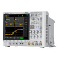
Agilent Technologies InfiniiVision 4000 X-Series User Manual (488 pages)
InfiniiVision 4000 X-Series
Brand:
Agilent Technologies
| Category:
Test Equipment
| Size: 9.5 MB
Table of Contents
Safety Notices
2
Infiniivision 4000 X-Series Oscilloscopes-At a Glance
3
Table of Contents
6
In this Guide
6
Getting Started
27
Inspect the Package Contents
27
Power-On the Oscilloscope
30
Tilt the Oscilloscope for Easy Viewing
30
Connect Probes to the Oscilloscope
31
Do Not Float the Oscilloscope Chassis
32
Input a Waveform
32
Maximum Input Voltage at Analog Inputs
32
Recall the Default Oscilloscope Setup
33
Use Auto Scale
33
Compensate Passive Probes
35
Learn the Front Panel Controls and Connectors
36
Horizontal Controls," Starting on
39
Vertical Controls," Starting on
42
Front Panel Overlays for Different Languages
43
Learn the Touchscreen Controls
45
Draw Rectangles for Waveform Zoom or Zone Trigger Set up
45
Drag Waveforms Left and Right to Change the Horizontal Position
46
Select Sidebar Information or Controls
47
Undock Sidebar Dialogs by Dragging
48
Select Dialog Menus and Close Dialogs
49
Drag Cursors
49
Touch Softkeys and Menus on the Screen
49
Enter Names Using Alpha-Numeric Keypad Dialogs
50
Enter Names Using Alpha- Numeric Keypad Dialogs
50
Change Waveform Offsets by Dragging Ground Reference Icons
51
Access Controls and Menus Via the Spark Icon
52
Turn Channels On/Off and Open Scale/Offset Dialogs
54
Access the Horizontal Menu and Open the Scale/Delay Dialog
54
Access the Trigger Menu, Change the Trigger Mode, and Open the Trigger Level Dialog
55
Use a USB Mouse And/Or Keyboard for Touchscreen Controls
56
Learn the Rear Panel Connectors
56
Digital Channels," Starting on
58
Learn the Oscilloscope Display
58
Access the Built-In Quick Help
60
Horizontal Controls
63
To Adjust the Horizontal (Time/DIV) Scale
65
To Adjust the Horizontal Delay (Position)
65
Panning and Zooming Single or Stopped Acquisitions
66
To Change the Horizontal Time Mode (Normal, XY, or Roll)
67
XY Time Mode
68
To Display the Zoomed Time Base
71
To Change the Horizontal Scale Knob's Coarse/Fine Adjustment Setting
73
To Position the Time Reference (Left, Center, Right)
73
Searching for Events
74
To Set up Searches
74
Triggers," Starting on
75
To Copy Search Setups
75
Navigating the Time Base
75
To Navigate Time
76
To Navigate Search Events
76
To Navigate Segments
77
Vertical Controls
80
To Turn Waveforms on or off (Channel or Math)
80
To Adjust the Vertical Scale
81
To Adjust the Vertical Position
81
To Specify Channel Coupling
82
To Specify Channel Input Impedance
83
To Specify Bandwidth Limiting
83
To Change the Vertical Scale Knob's Coarse/Fine Adjustment Setting
84
To Invert a Waveform
84
Setting Analog Channel Probe Options
85
To Specify the Channel Units
85
To Specify the Probe Attenuation
86
To Specify the Probe Skew
86
To Calibrate a Probe
87
Math Waveforms
89
To Display Math Waveforms
89
To Adjust the Math Waveform Scale and Offset
91
Units for Math Waveforms
91
Math Operators
92
Add or Subtract
92
Multiply or Divide
93
Math Transforms
94
Differentiate
95
Integrate
96
FFT Measurement
98
Square Root
106
Ax + B
106
Square
107
Absolute Value
108
Common Logarithm
108
Natural Logarithm
109
Exponential
109
Base 10 Exponential
110
Math Filters
110
High Pass and Low Pass Filter
111
Averaged Value
112
Math Visualizations
112
Magnify
112
Measurement Trend
113
Chart Logic Bus Timing
115
Chart Logic Bus State
116
Reference Waveforms
119
To Save a Waveform to a Reference Waveform Location
119
To Display a Reference Waveform
120
To Scale and Position Reference Waveforms
121
To Adjust Reference Waveform Skew
122
To Display Reference Waveform Information
122
To Save/Recall Reference Waveform Files To/From a USB Storage Device
122
Digital Channels
123
To Connect the Digital Probes to the Device under Test
123
Probe Cable for Digital Channels
124
Acquiring Waveforms Using the Digital Channels
127
To Display Digital Channels Using Autoscale
127
Interpreting the Digital Waveform Display
129
To Change the Displayed Size of the Digital Channels
130
To Switch a Single Channel on or off
130
To Switch All Digital Channels on or off
130
To Switch Groups of Channels on or off
130
To Change the Logic Threshold for Digital Channels
131
To Reposition a Digital Channel
131
To Display Digital Channels as a Bus
132
Digital Channel Signal Fidelity: Probe Impedance and Grounding
135
Input Impedance
136
Probe Grounding
138
Best Probing Practices
140
To Replace Digital Probe Leads
140
Serial Decode
143
Serial Decode Options
143
Lister
144
Searching Lister Data
146
Display Settings
149
To Adjust Waveform Intensity
149
To Set or Clear Persistence
151
To Clear the Display
153
To Select the Grid Type
153
To Adjust the Grid Intensity
153
To Display Waveforms as Vectors or Dots
154
To Freeze the Display
155
Labels
157
To Turn the Label Display on or off
157
To Assign a Predefined Label to a Channel
158
To Define a New Label
159
To Load a List of Labels from a Text File You Create
160
To Reset the Label Library to the Factory Default
161
To Add an Annotation
162
Triggers
165
Adjusting the Trigger Level
167
Forcing a Trigger
167
Edge Trigger
168
Edge then Edge Trigger
170
Pulse Width Trigger
172
Pattern Trigger
175
Hex Bus Pattern Trigger
178
OR Trigger
178
Rise/Fall Time Trigger
180
Nth Edge Burst Trigger
182
Runt Trigger
183
Setup and Hold Trigger
186
Video Trigger
187
To Set up Generic Video Triggers
192
To Trigger on a Specific Line of Video
193
To Trigger on All Sync Pulses
194
To Trigger on a Specific Field of the Video Signal
195
To Trigger on All Fields of the Video Signal
196
To Trigger on Odd or Even Fields
197
Serial Trigger
200
Zone Qualified Trigger
201
Trigger Mode/Coupling
205
To Select the Auto or Normal Trigger Mode
206
To Select the Trigger Coupling
208
To Enable or Disable Trigger Noise Rejection
209
To Enable or Disable Trigger HF Reject
209
To Set the Trigger Holdoff
210
External Trigger Input
210
Maximum Voltage at Oscilloscope External Trigger Input
211
Acquisition Control
213
Running, Stopping, and Making Single Acquisitions (Run Control)
213
Overview of Sampling
215
Sampling Theory
215
Aliasing
215
Oscilloscope Bandwidth and Sample Rate
216
Oscilloscope Rise Time
217
Oscilloscope Bandwidth Required
218
Memory Depth and Sample Rate
219
Selecting the Acquisition Mode
219
Normal Acquisition Mode
220
Peak Detect Acquisition Mode
220
Averaging Acquisition Mode
223
High Resolution Acquisition Mode
225
Chapter
225
Realtime Sampling Option
226
Realtime Sampling and Oscilloscope Bandwidth
227
Acquiring to Segmented Memory
228
Agilent Technologies InfiniiVision 4000 X-Series User Manual (486 pages)
Brand:
Agilent Technologies
| Category:
Test Equipment
| Size: 9.59 MB
Table of Contents
Safety Notices
2
Infiniivision 4000 X-Series Oscilloscopes-At a Glance
3
Table of Contents
6
In this Guide
6
Getting Started
27
Inspect the Package Contents
27
Power-On the Oscilloscope
30
Tilt the Oscilloscope for Easy Viewing
30
Connect Probes to the Oscilloscope
31
Do Not Float the Oscilloscope Chassis
32
Input a Waveform
32
Maximum Input Voltage at Analog Inputs
32
Recall the Default Oscilloscope Setup
33
Use Auto Scale
33
Compensate Passive Probes
35
Learn the Front Panel Controls and Connectors
36
Horizontal Controls," Starting on
39
Vertical Controls," Starting on
42
Front Panel Overlays for Different Languages
43
Learn the Touchscreen Controls
45
Draw Rectangles for Waveform Zoom or Zone Trigger Set up
45
Drag Waveforms Left and Right to Change the Horizontal Position
46
Select Sidebar Information or Controls
47
Undock Sidebar Dialogs by Dragging
48
Select Dialog Menus and Close Dialogs
49
Drag Cursors
49
Touch Softkeys and Menus on the Screen
49
Enter Names Using Alpha-Numeric Keypad Dialogs
50
Enter Names Using Alpha- Numeric Keypad Dialogs
50
Change Waveform Offsets by Dragging Ground Reference Icons
51
Access Controls and Menus Via the Spark Icon
52
Turn Channels On/Off and Open Scale/Offset Dialogs
54
Access the Horizontal Menu and Open the Scale/Delay Dialog
54
Access the Trigger Menu, Change the Trigger Mode, and Open the Trigger Level Dialog
55
Use a USB Mouse And/Or Keyboard for Touchscreen Controls
56
Learn the Rear Panel Connectors
56
Digital Channels," Starting on
58
Learn the Oscilloscope Display
58
Access the Built-In Quick Help
60
Horizontal Controls
63
To Adjust the Horizontal (Time/DIV) Scale
65
To Adjust the Horizontal Delay (Position)
65
Panning and Zooming Single or Stopped Acquisitions
66
To Change the Horizontal Time Mode (Normal, XY, or Roll)
67
XY Time Mode
68
To Display the Zoomed Time Base
71
To Change the Horizontal Scale Knob's Coarse/Fine Adjustment Setting
73
To Position the Time Reference (Left, Center, Right)
73
Searching for Events
74
To Set up Searches
74
Triggers," Starting on
75
To Copy Search Setups
75
Navigating the Time Base
75
To Navigate Time
76
To Navigate Search Events
76
To Navigate Segments
77
Vertical Controls
80
To Turn Waveforms on or off (Channel or Math)
80
To Adjust the Vertical Scale
81
To Adjust the Vertical Position
81
To Specify Channel Coupling
82
To Specify Channel Input Impedance
83
To Specify Bandwidth Limiting
83
To Change the Vertical Scale Knob's Coarse/Fine Adjustment Setting
84
To Invert a Waveform
84
Setting Analog Channel Probe Options
85
To Specify the Channel Units
85
To Specify the Probe Attenuation
86
To Specify the Probe Skew
86
To Calibrate a Probe
87
Math Waveforms
89
To Display Math Waveforms
89
To Adjust the Math Waveform Scale and Offset
91
Units for Math Waveforms
91
Math Operators
92
Add or Subtract
92
Multiply or Divide
93
Math Transforms
94
Differentiate
95
Integrate
96
FFT Measurement
98
Square Root
106
Ax + B
106
Square
107
Absolute Value
108
Common Logarithm
108
Natural Logarithm
109
Exponential
109
Base 10 Exponential
110
Math Filters
110
High Pass and Low Pass Filter
111
Averaged Value
112
Math Visualizations
112
Magnify
112
Measurement Trend
113
Chart Logic Bus Timing
115
Chart Logic Bus State
116
Reference Waveforms
119
To Save a Waveform to a Reference Waveform Location
119
To Display a Reference Waveform
120
To Scale and Position Reference Waveforms
121
To Adjust Reference Waveform Skew
122
To Display Reference Waveform Information
122
To Save/Recall Reference Waveform Files To/From a USB Storage Device
122
Digital Channels
123
To Connect the Digital Probes to the Device under Test
123
Probe Cable for Digital Channels
124
Acquiring Waveforms Using the Digital Channels
127
To Display Digital Channels Using Autoscale
127
Interpreting the Digital Waveform Display
129
To Change the Displayed Size of the Digital Channels
130
To Switch a Single Channel on or off
130
To Switch All Digital Channels on or off
130
To Switch Groups of Channels on or off
130
To Change the Logic Threshold for Digital Channels
131
To Reposition a Digital Channel
131
To Display Digital Channels as a Bus
132
Digital Channel Signal Fidelity: Probe Impedance and Grounding
135
Input Impedance
136
Probe Grounding
138
Best Probing Practices
140
To Replace Digital Probe Leads
140
Serial Decode
143
Serial Decode Options
143
Lister
144
Searching Lister Data
146
Display Settings
149
To Adjust Waveform Intensity
149
To Set or Clear Persistence
151
To Clear the Display
153
To Select the Grid Type
153
To Adjust the Grid Intensity
153
To Display Waveforms as Vectors or Dots
154
To Freeze the Display
155
Labels
157
To Turn the Label Display on or off
157
To Assign a Predefined Label to a Channel
158
To Define a New Label
159
To Load a List of Labels from a Text File You Create
160
To Reset the Label Library to the Factory Default
161
To Add an Annotation
162
Triggers
165
Adjusting the Trigger Level
167
Forcing a Trigger
167
Edge Trigger
168
Edge then Edge Trigger
170
Pulse Width Trigger
172
Pattern Trigger
175
Hex Bus Pattern Trigger
177
OR Trigger
178
Rise/Fall Time Trigger
180
Nth Edge Burst Trigger
182
Runt Trigger
183
Setup and Hold Trigger
185
Video Trigger
186
To Set up Generic Video Triggers
191
To Trigger on a Specific Line of Video
192
To Trigger on All Sync Pulses
193
To Trigger on a Specific Field of the Video Signal
194
To Trigger on All Fields of the Video Signal
195
To Trigger on Odd or Even Fields
196
Serial Trigger
199
Zone Qualified Trigger
200
Trigger Mode/Coupling
203
To Select the Auto or Normal Trigger Mode
204
To Select the Trigger Coupling
206
To Enable or Disable Trigger Noise Rejection
207
To Enable or Disable Trigger HF Reject
207
To Set the Trigger Holdoff
208
External Trigger Input
208
Maximum Voltage at Oscilloscope External Trigger Input
209
Acquisition Control
211
Running, Stopping, and Making Single Acquisitions (Run Control)
211
Overview of Sampling
213
Sampling Theory
213
Aliasing
213
Oscilloscope Bandwidth and Sample Rate
214
Oscilloscope Rise Time
215
Oscilloscope Bandwidth Required
216
Memory Depth and Sample Rate
217
Selecting the Acquisition Mode
217
Normal Acquisition Mode
218
Peak Detect Acquisition Mode
218
Averaging Acquisition Mode
221
High Resolution Acquisition Mode
223
Chapter
223
Realtime Sampling Option
224
Realtime Sampling and Oscilloscope Bandwidth
225
Acquiring to Segmented Memory
226
Advertisement
Advertisement
Related Products
Agilent Technologies InfiniiVision 4000 X Series
Agilent Technologies 4072A Advanced
Agilent Technologies 4072B Advanced
Agilent Technologies 4073A Ultra Advanced
Agilent Technologies 4073B Ultra Advanced
Agilent Technologies 4037A
Agilent Technologies 4037U
Agilent Technologies 42D
Agilent Technologies 42A
Agilent Technologies 41900A
Agilent Technologies Categories
Measuring Instruments
Laboratory Equipment
Test Equipment
Water Pump
Power Supply
More Agilent Technologies Manuals
Login
Sign In
OR
Sign in with Facebook
Sign in with Google
Upload manual
Upload from disk
Upload from URL