Agilent Technologies 4263B Manuals
Manuals and User Guides for Agilent Technologies 4263B. We have 6 Agilent Technologies 4263B manuals available for free PDF download: Operation Manual, User Manual, Configuration Manual
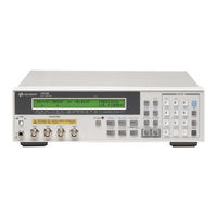
Agilent Technologies 4263B Operation Manual (331 pages)
LCR Meter
Brand: Agilent Technologies
|
Category: Measuring Instruments
|
Size: 2.51 MB
Table of Contents
Advertisement

Agilent Technologies 4263B Operation Manual (331 pages)
LCR Meter
Brand: Agilent Technologies
|
Category: Measuring Instruments
|
Size: 2.53 MB
Table of Contents

Agilent Technologies 4263B Operation Manual (325 pages)
LCR Meter
Brand: Agilent Technologies
|
Category: Measuring Instruments
|
Size: 5.31 MB
Table of Contents
Advertisement

Agilent Technologies 4263B User Manual (49 pages)
LCR Meter
Brand: Agilent Technologies
|
Category: Measuring Instruments
|
Size: 0.61 MB
Table of Contents

Agilent Technologies 4263B User Manual (48 pages)
LCD Meter
Brand: Agilent Technologies
|
Category: Measuring Instruments
|
Size: 0.74 MB
Table of Contents

Agilent Technologies 4263B Configuration Manual (8 pages)
LCR Meter, 100 Hz to 100 kHz
Brand: Agilent Technologies
|
Category: Measuring Instruments
|
Size: 0.24 MB