Sign In
Upload
Manuals
Brands
Afag Manuals
Industrial Equipment
CS 25/180
Afag CS 25/180 Compact Slide Control Manuals
Manuals and User Guides for Afag CS 25/180 Compact Slide Control. We have
3
Afag CS 25/180 Compact Slide Control manuals available for free PDF download: Assembly And Operating Instructions Manual, Montage & Maintenance Instructions
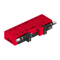
Afag CS 25/180 Assembly And Operating Instructions Manual (60 pages)
Compact Slide
Brand:
Afag
| Category:
Control Unit
| Size: 4 MB
Table of Contents
Table of Contents
3
General
6
Contents and Purpose of These Assembly Instructions
6
Explanation of Symbols
6
Additional Symbols
7
Applicable Documents
8
Warranty
8
Liability
8
Safety Instructions
9
General
9
Intended Use
9
Foreseeable Misuse
9
Obligations of the Operating Company
10
Observe the Assembly Instructions
10
Obligations of the Operator and the Personnel
10
Obligations of the Personnel
11
Personnel Requirements
11
Personnel Qualification
11
Personal Protective Equipment (PPE)
12
Changes & Modifications
12
General Hazards / Residual Risks
13
General Hazards at the Workplace
13
Danger Due to Electricity
14
Mechanical Hazards
14
Danger Due to Pneumatics
15
Danger Caused by Omitting Maintenance Work
15
Fig. 1 Dimensional Drawing Compact Slide CS 25
16
Dimensional Drawing CS 25
16
Technical Data
16
Technical Data CS 25
17
Fig. 2 Table Technical Data CS 25
17
Preferred Combinations CS 25
18
Slide Loads CS 25
19
Fig. 3 Table of Slide Loads CS 25
19
Operation Time Diagram CS 25
20
Transport, Packaging and Storage
21
Safety Instructions for Transport
21
Fig. 4 CS Compact Slide in Original Packaging
21
Scope of Supply
22
Transport
22
Packaging
23
Storage
23
Fig. 5 Design of the CS Module
24
Design and Description
24
Product Description
24
Design Compact Slide
24
Accessories CS 25
25
Installation, Assembly & Setting
27
Safety Instructions for Installation & Assembly
27
Installation & Assembly
28
Assembly & Attachment
28
Fig. 6 Mounting Base Screwed through Mounting Base below M8
28
Tightening Torques for Screws
29
Connection to the Pneumatic System
30
Fig. 7 Pneumatic Circuit Diagram Compact Slide
31
Fig. 8 Pneumatic Circuit Diagram Compact Slide CS 25 with ZA
31
Fig. 10 Mounting the Inductive Initiator
32
Fig. 9 A+B: Holder of Inductive Initiators
32
Installation of the Initiator
32
Installation and Adjustment of the Proximity Switch
33
Fig. 11 Installation and Adjustment of the Compact Slide
33
Query Sensors
34
Adjustment of the Shock Absorber
35
Safety Notes for Settings
35
Adjusting the Shock Absorbers and Stop Screws
36
Fig. 12 Maximum Damper Effect
36
Fig. 13 Reduced Damper Effect
36
End Position Control for Entire Stroke Range
37
Fig. 14 Mounting the Proximity Switch in the ZA Module
37
Fig. 15 Sensor (Adjustable) End Position Sensing (Max. Stroke)
37
Fig. 16 before (Normal State) after (with Reduced Stroke)
37
Sequence of Intermediate Positions During Extension
38
Sequence of the Intermediate Position
38
Sequence of Intermediate Positions During Retraction
39
ZA Intermediate Stop (Option)
40
ZA Intermediate Stop - Overview
40
Fig. 17 Overview of the ZA Intermediate Stop
40
Mounting the ZA Intermediate Stop on the CS Module
41
Fig. 18 Mount the ZA Intermediate Stop
41
Fig. 19 Illustration of the ZA Module - Extension
41
Fine Adjustment of the Stop Screw with Shock Absorber
42
Fig. 20 Fine Adjustment Stop Screw
42
Fig. 21 Mounting the Proximity Switch in the ZA Module
42
Adjustment to Other Action Direction
43
Set the ZA-Catch to a Different Action Direction
43
ZA-Catch to Other Acting Direction (Procedure for Retraction or Extension)
43
Dismantle ZA-Catch
44
Fig. 22 Illustration of ZA-Catch with Cylinder
44
Safety Instructions for Commissioning
45
Commissioning
45
Preparations for Commissioning
46
Fig. 23 Installation and Adjustment of the Compact Slide
46
Commissioning of the Modules
47
Fig. 24 Commissioning the Compact Slides
47
Fault Elimination
48
General Notes
48
Safety Instructions for Troubleshooting
48
Maintenance and Repair
49
General Notes
49
Safety Instructions for Maintenance and Repair
49
Fig. 25 Maintenance Points Compact Slide (CS 25)
50
Maintenance Activities and Maintenance Intervals
50
Overview of the Maintenance Points
50
Compressed Air Specifications
51
Further Maintenance
52
Spare and Wear Parts Lists, Repairs
52
General Notes
52
Safety Instructions
52
Decommissioning, Disassembly, Disposal
53
Safety Instructions for Decommissioning, Disassembling and Disposal
53
Decommissioning
53
Disassembly
53
Disposal
54
Declaration of Incorporation
55
List of Figures
57
Advertisement
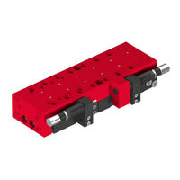
Afag CS 25/180 Assembly And Operating Instructions Manual (56 pages)
Compact Slide
Brand:
Afag
| Category:
Industrial Equipment
| Size: 2 MB
Table of Contents
Table of Contents
3
General
6
Contents and Purpose of These Assembly Instructions
6
Explanation of Symbols
6
Additional Symbols
7
Applicable Documents
8
Warranty
8
Liability
8
Safety Instructions
9
General
9
Intended Use
9
Foreseeable Misuse
9
Obligations of the Operator and the Personnel
10
Observe the Assembly Instructions
10
Obligations of the Operating Company
10
Obligations of the Personnel
11
Personnel Requirements
11
Personnel Qualification
11
Personal Protective Equipment (PPE)
12
Changes & Modifications
12
General Hazards / Residual Risks
13
General Hazards at the Workplace
13
Danger Due to Electricity
14
Mechanical Hazards
14
Danger Due to Pneumatics
15
Danger Caused by Omitting Maintenance Work
15
Technical Data
16
Dimensional Drawing CS 25
16
Technical Data CS 25
17
Preferred Combinations CS 25
18
Slide Loads CS 25
19
Operation Time Diagram CS 25
20
Transport, Packaging and Storage
21
Safety Instructions for Transport
21
Scope of Supply
22
Transport
22
Packaging
23
Storage
23
Design and Description
24
Design Compact Slide
24
Product Description
24
Accessories CS 25
25
Installation, Assembly & Setting
27
Safety Instructions for Installation & Assembly
27
Installation & Assembly
28
Assembly & Attachment
28
Tightening Torques for Screws
29
Connection to the Pneumatic System
30
Installation of the Initiator
32
Installation and Adjustment of the Proximity Switch
33
Query Sensors
34
Adjustment of the Shock Absorber
35
Safety Notes for Settings
35
Adjusting the Shock Absorbers and Stop Screws
36
End Position Control for Entire Stroke Range
37
Sequence of the Intermediate Position
38
Sequence of Intermediate Positions During Extension
38
Sequence of Intermediate Positions During Retraction
39
ZA Intermediate Stop (Option)
40
ZA Intermediate Stop - Overview
40
Mounting the ZA Intermediate Stop on the CS Module
41
Fine Adjustment of the Stop Screw with Shock Absorber
42
Adjustment to Other Action Direction
43
Set the ZA-Catch to a Different Action Direction
43
ZA-Catch to Other Acting Direction (Procedure for Retraction or Extension)
43
Dismantle ZA-Catch
44
Commissioning
45
Safety Instructions for Commissioning
45
Preparations for Commissioning
46
Commissioning of the Modules
47
Fault Elimination
48
General Notes
48
Safety Instructions for Troubleshooting
48
Maintenance and Repair
49
General Notes
49
Safety Instructions for Maintenance and Repair
49
Maintenance Activities and Maintenance Intervals
50
Overview of the Maintenance Points
50
Compressed Air Specifications
51
Further Maintenance
52
Spare and Wear Parts Lists, Repairs
52
General Notes
52
Safety Instructions
52
Decommissioning, Disassembly, Disposal
53
Safety Instructions for Decommissioning, Disassembling and Disposal
53
Decommissioning
53
Disassembly
53
Disposal
54
Declaration of Incorporation
55
Afag CS 25/180 Montage & Maintenance Instructions (44 pages)
Brand:
Afag
| Category:
Industrial Equipment
| Size: 3 MB
Table of Contents
Table of Contents
3
EC Declaration for Incorporation (Document Original)
5
According To: 2006/42/EC
5
Module Information
6
Transport and Storage (Packing and Unpacking)
6
Possibilities of Fastening the CS 25
7
Centering Bushings and Hole Matrix
7
Tightening Moments for Screws
9
Slide Unit Load Factors
10
Preferred Combinations for CS 25
11
Montage Instructions
12
The Manufacturer: Afag Automation AG
12
Symbols
12
General Description
13
Description of the CS 25 Module
14
Scope of Supply
15
Intended Use
15
Warranty
16
Areas of Application
16
Dimension CS 25
17
Technical Data
18
Pneumatic Connections
19
Preparation for Start-Up
20
Setting the Shock Absorbers and the Stop Screws
21
Inquiry of the Sensors
22
Accessories
22
Fitting the Proximity Switch in the Module Grooves
23
Fitting the Initiator
24
Check of the Final Position in the Total Stroke Range
25
Start-Up of the CS 25 Compact Slide
26
Optional ZA Intermediate Stop for the CS 25
26
Attaching the ZA Intermediate Stop to the CS 25
27
Attaching the ZA Intermediate Stop to the CS 25 Module
28
Fine Adjustment of the Stop Screw with Shock Absorber
29
Operating Sequence of the Intermediate Position When Extending
30
Changing the ZA Catch
32
Modification of the ZA for the Reverse Action Direction
32
Maintenance Instructions
35
Maintenance and Servicing of the CS 25 Compact Slide
35
Servicing
36
Accessories for the CS 25
37
Faults During Operation
40
Disassembly and Repair
41
Disposal
42
Advertisement
Advertisement
Related Products
Afag CS 25 Series
Afag CS 25/60
Afag CS 25/120
Afag CS 25/240
Afag CS 20/100
Afag CS 6
Afag CS 16/60
Afag CS 16/120
Afag CS 6/20-ED
Afag CS 8/60-SDA
Afag Categories
Industrial Equipment
Control Unit
Controller
Wire Feeders
DC Drives
More Afag Manuals
Login
Sign In
OR
Sign in with Facebook
Sign in with Google
Upload manual
Upload from disk
Upload from URL