Sign In
Upload
Manuals
Brands
Aerotech Manuals
DC Drives
ANT130XY Series
Aerotech ANT130XY Series Nanopositioning Manuals
Manuals and User Guides for Aerotech ANT130XY Series Nanopositioning. We have
1
Aerotech ANT130XY Series Nanopositioning manual available for free PDF download: Hardware Manual
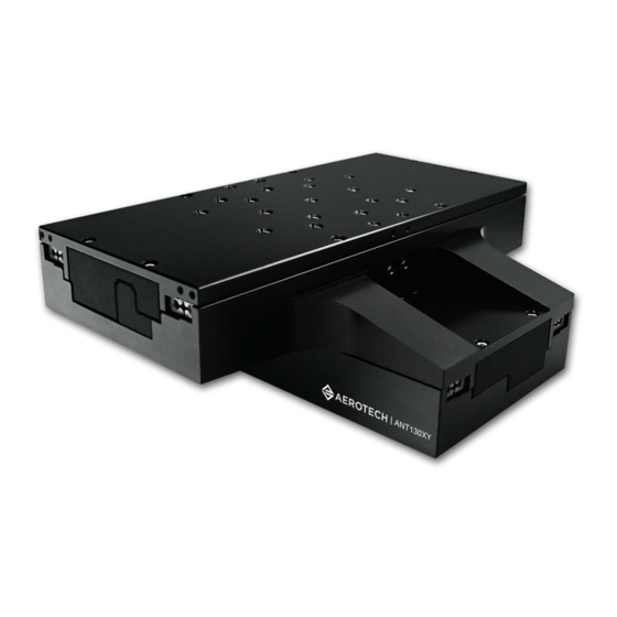
Aerotech ANT130XY Series Hardware Manual (50 pages)
Two-Axis Direct-Drive Nanopositioning Stage
Brand:
Aerotech
| Category:
DC Drives
| Size: 1.86 MB
Table of Contents
ANT130XY Series Two-Axis Direct-Drive Nanopositioning Stage
1
Table of Contents
3
List of Figures
4
List of Tables
5
EU Declaration of Incorporation
6
Safety Procedures and Warnings
7
Warnings
7
Installation and Operation
8
Electrical Warnings
9
Motor-Related Warnings
10
Pinch Points
11
Magnetic Hazards
12
Handling and Storage
13
Serial Number
13
Stabilizing
13
Stabilizing Stage
13
Storage
13
Chapter 1: Overview
17
Figure 1-1: GEN2 Vs GEN1 Visual Comparison
17
Table 1-1: Model Numbers and Ordering Options
17
Environmental Specifications
18
Accuracy and Temperature Effects
18
Table 1-2: Environmental Specifications
18
Temperature Effects
18
Vibration
18
Basic Specifications
19
Table 1-3: ANT130XY-060 Series Specifications
19
Resolution 19 Yaw
19
Roll
19
Solution
19
Specifications
19
Speed
19
Stage Mass
19
Straightness
19
Travel
19
Vacuum Operation
20
Vacuum Guidelines
20
Vacuum Lubricant (Braycote 602EF)
20
Chapter 2: Installation
21
Dimensions
21
Figure 2-1: ANT130XY Dimensions
21
Figure 2-2: Mounting Plate (MP) Dimensions
22
Figure 2-3: Cable Management Post (CMS) Dimensions
23
Securing the Stage to the Mounting Surface
24
Table 2-1: Stage Mounting Surface Flatness Requirement
24
Shimming
24
Figure 2-4: Mounting Hole Pattern
25
Table 2-2: Stage to Mounting Surface Hardware
25
Attaching the Payload to the Stage
26
Table 2-3: Payload to Stage Surface Hardware
26
Figure 2-5: Load Orientations
27
Figure 2-6: Cantilevered Load Capabilities
27
Chapter 3: Electrical Installation
29
Motor and Feedback Connectors
30
Table 3-1: 25-Pin Motor and Feedback Connector Pinout (-CN1)
31
Table 3-2: 25-Pin Mating Connector Part Numbers
31
Table 3-3: 4-Pin Motor Connector Pinout (-CN2 Option)
32
Table 3-4: 4-Pin Motor Mating Connector Part Numbers
32
Table 3-5: 25-Pin Feedback Connector Pinout (-CN2 Option)
33
Table 3-6: 25-Pin Feedback Mating Connector Part Numbers
33
Motor and Feedback Wiring
34
Figure 3-1: ANT130XY Motor and Feedback Wiring [-CN1 Option]
34
Figure 3-2: ANT130XY Motor and Feedback Wiring [-CN2 Option]
35
Motor and Feedback Specifications
36
Table 3-7: Hall-Effect Sensor Specifications
36
Table 3-8: Thermistor Specifications
36
Table 3-9: Encoder Specifications
36
Table 3-10: Limit Switch Specifications
36
Encoder
36
Hall-Effect Sensors
36
Limit Switch
36
Thermistor Specifications
36
Table 3-11: ANT130XY Motor Specifications
37
Table 3-12: Encoder Resolution
37
Limits, Marker, and Machine Direction
38
Figure 3-3: Machine Direction
38
Motor and Feedback Phasing
39
Figure 3-4: Hall Phasing Diagram
39
Chapter 4: Maintenance
41
Service and Inspection Schedule
41
Cleaning and Lubrication
42
Solvents
42
Troubleshooting
44
Symptom
44
Appendix A: Warranty and Field Service
45
Warranty and Field Service
45
Appendix B: Revision History
47
Index
49
Advertisement
Advertisement
Related Products
Aerotech ANT130XY-060
Aerotech ANT130L Series
Aerotech ANT130L-035
Aerotech ANT130L-060
Aerotech ANT130L-110
Aerotech ANT130L-160
Aerotech ANT130L-210
Aerotech ANT95LZS-050
Aerotech ANT95LZ Series
Aerotech ANT95LZ-025
Aerotech Categories
Industrial Equipment
DC Drives
Controller
Engine
Amplifier
More Aerotech Manuals
Login
Sign In
OR
Sign in with Facebook
Sign in with Google
Upload manual
Upload from disk
Upload from URL