Sign In
Upload
Manuals
Brands
Aeroflex Manuals
Measuring Instruments
9102
Aeroflex 9102 Manuals
Manuals and User Guides for Aeroflex 9102. We have
1
Aeroflex 9102 manual available for free PDF download: User Manual
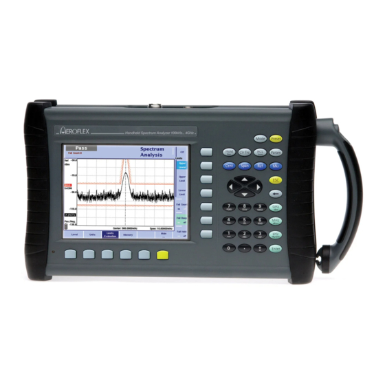
Aeroflex 9102 User Manual (416 pages)
Handheld Spectrum Analyzer
Brand:
Aeroflex
| Category:
Measuring Instruments
| Size: 2 MB
Table of Contents
Table of Contents
5
About this Guide
17
Assumptions
18
Purpose and Scope
18
Related Information
18
Technical Assistance
18
Conventions
19
Safety Notes
21
Safety Warnings
22
Chapter 1 Overview
23
About the 9102 Handheld Spectrum Analyzer
24
What's New
25
Version 4.11
25
Version 4.50
25
Version 5.00
25
Version 5.10
25
Version 5.12
25
Version 5.20
25
Version 5.30
25
Version 5.31
25
Version 3.10
26
Version 4.01
26
Version 4.10
26
Version 3.01
27
Features and Capabilities
27
Options and Accessories
27
Physical Description
32
Maintaining Your Unit
32
Chapter 2 General Operation
35
Connecting the 9102 Handheld Spectrum Analyzer
36
DC in Connector
36
RF in Connector
36
EXT . REF . in / EXT . TRIG . Connector
37
Headphone Jack
37
Multi Port
37
RF out Connector
37
LAN Connector
38
SERIAL (RS-232) Connector
38
Powering up the Unit
39
Starting Measurements
39
Using the Front Panel
39
Battery Status LED
39
Overview
39
Display
40
Results Area
41
Marker Field
43
Trace Finder
43
Function Keys
44
Input Field
44
Keypad
44
Softkey Descriptions
44
Cursor Keys
46
Numeric Keys
46
Backspace Key
47
Enter Keys
47
Escape Key
47
Softkeys
47
Entering Numbers and Text
49
Filling in a Numerical Input Field
49
Filling in a Text Input Field
50
Changing the Input
51
Selecting the Measurement Mode
51
Working with the Markers
53
Enabling and Moving a Marker
53
Disabling a Delta Marker
54
Disabling a Marker
54
Enabling a Delta Marker
54
Changing the Center Frequency with a Marker
55
Changing the Reference Level with the Marker
55
Setting a Marker on a Frequency Relative to Marker 1
55
Assigning the Marker Frequency to Fstep
56
Using Limit Lines
56
Overview
57
Using Simple Limits
57
Defining Upper and Lower Limits
58
Switching Simple Limits on and off
58
Using Limit Templates
58
Activating and Deactivating Limit Templates
59
Counting Limit Failures
59
Deleting Limit Files in the 9102
59
Selecting Limit Lines Within the 9102
59
Enabling a Beep Upon Failures
60
Resetting the Counter
60
Viewing a Failed Measurement
60
Printing
60
Logging the Current Position (GPS-Assisted)
61
Connecting the GPS Receiver
61
Enabling the GPS Receiver
61
Taking GPS-Assisted Location Measurements
62
Changing the GPS Display Settings
63
Controlling the 9102 from a PC
63
Returning from Remote Control to Local Mode
63
Checking General Settings
63
Reading the Serial Number
63
Reading the Software Version Number
64
Reviewing the Calibration
64
Checking Installed Options
65
Changing the Display Brightness
66
Installing a New Option
66
Assigning a Device Name to the Instrument
67
Enabling and Disabling Beeps
67
Adjusting Date and Time in the Instrument
68
Changing the Baud Rate on the RS-232 Port
68
Changing the IP Address of the 9102
69
Changing the IP Address of the PC
70
Changing the IP Port Used by the 9102
71
Configuring a Printer
72
Selecting User Interface Colors
72
Working with Stored Settings
74
Storing Instrument Settings
74
Deleting a Settings File
75
Reloading Instrument Settings
75
Reusing an Instrument Settings Name
75
Deleting All Intrument Settings Files
76
Restoring Factory Settings for All Modes
76
Improving the Frequency Accuracy
76
Chapter 3 Spectrum Analysis Operation
77
Selecting the Measurement Mode
78
Changing the Frequency Settings
78
Setting Center Frequency and Span
79
Setting Start and Stop Frequency
79
Changing the Main Menu for Different Frequency Parameters
80
Performing Measurements in the Time Domain
80
Selecting the Step Size for the Frequency Input
80
Viewing the Complete Frequency Band
80
Selecting RBW, VBW and SWT
81
Setting up the Level Parameters
82
Setting the Hardware Attenuation
82
Setting the Reference Level
82
Changing the Vertical Scale
83
Compensating Gains and Losses
83
Enabling External Device Compensation
83
Selecting the Level Unit for Input and Output
83
Deleting Files for External Device Compensation
84
Turning External Device Compensation off
84
Changing the Input Impedance
84
Applying Special Functions on the Signal
86
Using a Trigger
86
Demodulating an am or FM Signal
88
Performing a Limited Number of Measurements
88
Setting up the Trace
89
Selecting the Trace Mode
90
Subtracting Trace B from Trace a
91
Turning the Second Trace on and off
91
Adding Trace B to Trace a
92
Defining the Number of Measurements for Averaging
93
Selecting the Detection Method
93
Copying Traces Inside the 9102
94
Storing and Loading Traces
95
Storing a Trace
95
Deleting a Trace
96
Deleting All Traces
96
Reloading a Trace
96
Reusing a Trace Name
96
Special Measurement Functions
97
Adjacent Channel Power Ratio (ACPR)
97
Channel Power
97
Occupied Bandwidth (OBW)
98
Selecting the Measurement Type
99
Switching Special Measurement Functions off
99
Changing the Channel Spacing
100
Changing the Channel Width
100
Changing the Occupied Bandwidth Percentage
100
Reading the Channel Power
100
Changing General Analyzer Parameters
101
Viewing the Spectrum Analysis Mode Parameters
101
Chapter 4 Channel Power Operation
103
About the Channel Power Mode
104
Channel Power
105
Adjacent Channel Power Ratio (ACPR)
106
Occupied Bandwidth (OBW)
106
Selecting the Measurement Mode
107
Operating in Channel Power Mode
108
Reading the Channel Power
109
Changing the Occupied Bandwidth Percentage
109
Working with Communication Systems and Frequency Settings
109
Selecting a Communication System on the 9102
109
Setting up a New Communication System
110
Deleting a Communication System
111
Deleting All Communication Systems
111
Undeleting Default Communication Systems
111
Using the 9100 Data Exchange Software with Communication Systems
111
Changing the Channel
112
Defining the Frequency Span
112
Changing the Sweep Time
112
Setting up the Level Parameters
112
Setting the Hardware Attenuation
113
Setting the Reference Level
113
Changing the Vertical Scale
114
Compensating Gains and Losses
114
Enabling External Device Compensation
114
Selecting the Level Unit for Input and Output
114
Deleting Files for External Device Compensation
115
Turning External Device Compensation off
115
Changing the Input Impedance
115
Setting up the Trace
116
Selecting the Trace Mode
116
Subtracting Trace B from Trace a
118
Turning the Second Trace on and off
118
Adding Trace B to Trace a
119
Defining the Number of Measurements for Averaging
119
Selecting the Detection Method
119
Copying Traces Inside the 9102
120
Storing and Loading Traces
121
Storing a Trace
121
Deleting a Trace
122
Deleting All Traces
122
Reloading a Trace
122
Reusing a Trace Name
122
Viewing the Channel Power Mode Parameters
123
Chapter 5 Power Sensor Operation
125
About the Power Sensor Mode
126
Connecting the 9162 Insertion Power Sensor
127
Setting up the 9102 for Insertion Power Measurements
128
Setting up the Signal Type and Frequency
128
Starting the Insertion Power Mode
128
Defining the Displayed Measurement Unit
129
Reading the Power Measurement
129
Forward Power
129
Reverse Power
129
Chapter 6 Signal Generator Operation
131
About the Signal Generator Mode
132
Selecting the Measurement Mode
132
Switching the Signal Generator on and off
132
Changing the Frequency
132
Selecting the Frequency Mode
132
Setting the Center Frequency
133
Selecting the Step Size for the Frequency Input
134
Setting Start and Stop Frequency
134
Setting the Level
135
Applying Special Functions on the Signal
135
Performing a Limited Number of Measurements
135
Chapter 7 Transmission Operation
137
About the Transmission Mode
138
Selecting the Measurement Mode
138
Switching the Tracking Generator on and off
139
Normalizing the Trace
139
Setting the Tracking Output Power
140
Changing the Frequency Settings
141
Setting Start and Stop Frequency
141
Changing the Main Menu for Different Frequency Parameters
142
Setting Center Frequency and Span
142
Performing Measurements in the Time Domain
143
Selecting the Step Size for the Frequency Input
143
Viewing the Complete Frequency Band
143
Selecting RBW, VBW and SWT
144
Setting up the Level Parameters
144
Setting the Hardware Attenuation
145
Setting the Reference Level
145
Switching the Display
145
Changing the Vertical Scale
146
Compensating Gains and Losses
146
Enabling External Device Compensation
146
Turning External Device Compensation off
146
Deleting Files for External Device Compensation
147
Applying Special Functions on the Signal
147
Using a Trigger
147
Performing a Limited Number of Measurements
149
Setting up the Trace
149
Selecting the Trace Mode
151
Subtracting Trace B from Trace a
152
Turning the Second Trace on and off
152
Adding Trace B to Trace a
153
Defining the Number of Measurements for Averaging
153
Trace Offset
153
Copying Traces Inside the 9102
154
Selecting the Detection Method
154
Storing and Loading Traces
156
Storing a Trace
156
Deleting a Trace
157
Deleting All Traces
157
Reloading a Trace
157
Reusing a Trace Name
157
Viewing the Transmission Mode Parameters
158
Chapter 8 The 9130 VSWR/DTF Reflection Measurement Option
159
About the 9130 VSWR/DTF Reflection Measurement Option
160
Specifications
160
Measurement Modes
161
Hardware Requirements
162
Connecting the 9160 VSWR/DTF Bridge
162
Calibration
164
Chapter 9 Reflection Operation
165
About the Reflection Mode
166
Selecting the Measurement Mode
167
Preparative Steps
167
Changing the Frequency Settings
168
Setting Start and Stop Frequency
168
Changing the Main Menu for Different Frequency Parameters
169
Setting Center Frequency and Span
169
Performing Measurements in the Time Domain
170
Selecting the Step Size for the Frequency Input
170
Viewing the Complete Frequency Band
170
Reflection Calibration
171
Changing the Units Settings
172
Setting up the Level Parameters
173
Changing the Scale for VSWR
173
Changing the Vertical Scale for Return Loss
173
Setting the Maximum for VSWR
173
Setting the Reference Level for Return Loss
173
Changing the Scale for Reflection Factor
174
Changing the Scale for Reflection Power
174
Setting the Maximum for Reflection Factor
174
Setting the Maximum for Reflection Power
174
Performing a Limited Number of Measurements
176
Setting up the Trace
176
Selecting the Trace Mode
176
Adding Trace B to Trace a
178
Subtracting Trace B from Trace a
178
Turning the Second Trace on and off
178
Copying Traces Inside the 9102
179
Defining the Number of Measurements for Averaging
179
Trace Offset
179
Storing and Loading Traces
180
Reloading a Trace
180
Reusing a Trace Name
180
Storing a Trace
180
Deleting a Trace
181
Deleting All Traces
181
Using Limits
181
Viewing the Reflection Mode Parameters
182
Chapter 10 Distance to Fault Operation
185
About the Distance to Fault Mode
186
Selecting the Measurement Mode
187
Preparative Steps
187
Selecting the Measurement Unit
187
Specifying the Cable Length
188
Selecting the Distance Unit
188
Setting the Length
188
Specifying Cable Settings
188
Using Predefined Parameter Files
188
Specifying Parameters Step by Step
189
Setting Center Frequency and Span
189
Distance to Fault Calibration
190
Specifying the Level Parameters
192
Changing the Vertical Scale for Db
192
Setting the Maximum for Reflection Factor
192
Setting the Reference Level for Db
192
Changing the Scale for Reflection Factor
193
Setting up the Trace
193
Using Limits
193
Viewing the Distance to Fault Parameters
193
Chapter 11 Cable Loss Operation
195
About the Cable Loss Mode
196
Selecting the Measurement Mode
196
Preparative Steps
197
Changing the Frequency Settings
197
Setting Center Frequency and Span
198
Setting Start and Stop Frequency
198
Changing the Main Menu for Different Frequency Parameters
199
Performing Measurements in the Time Domain
199
Selecting the Step Size for the Frequency Input
199
Viewing the Complete Frequency Band
199
Cable Loss Calibration
200
Setting up the Level Parameters
201
Changing the Vertical Scale
201
Setting the Reference Level
201
Performing a Limited Number of Measurements
202
Using Limits
202
Viewing the Cable Loss Parameters
202
Chapter 12 EMF (EMI) Operation
203
About the EMF (EMI) Mode
204
EMF Measurements
205
Measurement Setup for Emission Measurements
206
Radiation Emission
206
Radiation Immission
206
Measurement Setup for Immission Measurements
207
Measurement Methods
207
Multipoint Method
209
Stirring Method
209
Measurement Antennas
210
9170 Biconical Antenna
211
9171 Isotropic Antenna
213
Directional Antennas
215
EMF Measurements with the 9102
216
Connecting the Antenna
218
Connecting a Directional Antenna
218
Connecting the 9170 Biconical Antenna
218
Connecting the 9171 Isotropic Antenna
218
Using a Tripod
218
Selecting the Measurement Mode
219
Selecting the Unit
219
Selecting the Frequency Range
220
Setting Center Frequency and Span
221
Setting Start and Stop Frequency
221
Changing the Main Menu for Different Frequency Parameters
222
Performing Measurements in the Time Domain
222
Selecting the Step Size for the Frequency Input
222
Viewing the Complete Frequency Band
222
Selecting RBW, VBW and SWT
223
Specifying the Display Calculation
224
Specifying Level Settings
224
Setting the Reference Level
224
Setting the Hardware Attenuation
225
Performing Automatic Measurements
225
Activating the Antenna Factor Settings
226
Specifying Cable Factor Settings for Extension Cables
226
Auto Measurements
227
Quick Measurements
229
Performing Manual Measurements
229
Performing the Measurement
230
Specifying Antenna Factor Settings
230
Specifying Cable Factor Settings for Extension Cables
230
Setting up the Trace
232
Using Limits
232
Using Markers
232
Viewing the EMF (EMI) Mode Parameters
232
Chapter 13 Troubleshooting
235
Recharging Problems with the 9102B
236
Handling System Errors
237
Chapter 14 Updating the Instrument Software
239
Entering the Setup Application Software Menu
240
Setting a Password
240
Performing a Serial Update
241
Performing a LAN Update
243
Determining the Host IP Address
244
Chapter 15 9100 Data Exchange Software
245
About the 9100 Data Exchange Software
246
Installation Requirements
246
Understanding the License Conditions
246
Installing the Software
246
Starting the Software
247
Connecting the PC to the 9102
248
Serial Interface Connection
248
Using a Predefined Configuration for the Connection
248
LAN (TCP/IP) Connection
249
Saving the Configuration
249
Loading Measurement Results from the 9102
249
Toggling the View Mode
250
Viewing the Actual Trace on the PC
250
Continually Loading Live Traces
251
Showing and Hiding Markers
251
Showing and Hiding Parameters
251
Transferring a Saved Trace to the PC
252
Saving, Loading and Printing Results on the PC
253
Affecting the Layout
253
Loading a Trace File on the PC
253
Printing Measurement Results
253
Storing Results on the PC
253
Printing a Trace
254
Printing Several Traces
254
Copying the Trace into a Document
255
Graphics Copy and Paste
255
Saving Results to a Graphics File
255
Saving Results to a Text File
255
Data Copy and Paste
256
Creating Screen Shots
257
Working with Measurement Results
258
Adding Markers
258
Change the Reference Level and Scale
260
Entering Text
261
Using a Grid
261
Defining and Loading Limit Templates
261
Defining Limits
262
Changing Limit Lines
263
Displaying an Example Trace in the Limits Editing Menu
263
Storing a Template on the PC
263
Loading a Template from the PC
264
Transferring a Template to the 9102
264
Defining and Loading External Coupling Parameters
265
Defining the External Coupling Factor
266
Loading an External Coupling Loss File to the 9102
266
Managing Communication Systems for Channel Power Measurements
267
Editing Communication System Parameters on the PC
267
Managing Cable Types for Distance-To-Fault Measurements
268
Uploading Predefined Cable Types to the Instrument
268
Defining Cable Types
269
Transferring Cable Types from the 9102
269
Managing Antenna Factors for EMF Measurements
270
Defining an Antenna Factor
271
Loading Antenna Factor Files to the 9102
271
Managing Cable Factors for EMF Measurements
272
Defining a Cable Factor
272
Loading Cable Factor Files to the 9102
273
Working with Settings
273
Changing 9102 Settings on the PC
273
Exchanging a Settings File between 9102 and PC
273
Managing Files on the PC and on the 9102
274
File Types and Directory Structure
274
Starting the File Manager
275
Copying Configuration Files from the 9102 to the PC
277
Deleting Files
277
Including the GPS Position in the Trace
277
Chapter 16 SCPI Command Reference
279
Overview
280
General Commands
280
Cal
281
Cls
281
Idn
281
Commands Affecting the Event Status Register
282
Opc
282
Commands Affecting the Service Register
283
Ese
283
Esr
283
System Commands
286
System:date
286
System:time
286
System:communicate:echo
287
System:communicate:ethernet
287
System:communicate:local
287
System:communicate:ser:baudrate
289
System:communicate:ser:terminator
289
System:error:code:all
290
System:error:code[:Next]
290
System:error[:Next]
290
System:dname
291
System:options
291
System:screendump:color
291
System:printer:baudrate
292
System:printer:type
292
System:screendump:line
292
System:screendump:remote
292
Sense Commands
293
Sense:trigger
299
Sense:trigger:edge
299
Sense:trigger:level
299
Sense:trace:copy
303
Sense:trace:data
304
Sense:trace:data:limit
304
Sense:trace:math
304
Sense:trace:math:[A|B]
304
Sense:trace:math:offset
305
Sense:transmission:reference
310
Sense:transmission:reference:unit
310
Input Commands
320
Mmemory Commands
321
Instrument Commands
333
Display Commands
339
Display:backlight:extern
341
Display:backlight[:Battery]
341
Display:beep
342
Calculate Commands
343
Calculate:marker:aoff
343
Calculate:marker:{A|B|C|D|E|F}[:State]
343
Calculate:marker:{A|B|C|D|E|F}:Dtf[:State]
344
Calculate:marker:{A|B|C|D|E|F}:Y
344
Calculate:marker:{A|B|C|D|E|F}:X:distance
345
Calculate:marker:{A|B|C|D|E|F}:X:time
345
Calculate:marker:{A|B|C|D|E|F}:X[:Frequency]
345
Calculate:marker:maxpeak
346
Calculate:marker:mcenter
346
Calculate:marker:npeak
346
Calculate:marker:{A|B|C|D|E|F}:Tselect
346
Calculate:{A|B|C|D|E|F}:Marker:fstep
346
Calculate:limit[:State]
347
Calculate:marker:fcount
347
Calculate:marker:fcount:resolution
347
Calculate:marker:mreflevel
347
Calculate:limit:fbeep
348
Calculate:limit:fcount
348
Calculate:limit:fcount:count
348
Calculate:limit:fhold
349
Calculate:limit:simple
349
Calculate:limit:simple:lower
349
Calculate:limit:simple:upper
349
Calculate:measure:acloss
350
Calculate:measure:acpr
350
Calculate:measure:cpower
350
Calculate:measure:obw
350
Calculate:measure:emf
351
Calculate:measure:psensor:fpower
351
Calculate:measure:psensor[:All]
351
Format Commands
352
Calculate:measure:psensor:rpower
352
Service Commands
353
Service:battery
353
Service:battery:serialnumber
353
Service:bootversion
353
Service:bootversion:date
353
Service:check:last
354
Service:check:next
354
Service:device:type
354
Service:powerline
354
Service:device:calibration:number
355
Service:device:text
355
Service:edevice:serialnumber
355
Service:edevice:type
355
SCPI Errors
356
Service:edevice:calibration:date
356
Service:edevice:text
356
Chapter 17 Programming Examples
361
Overview
362
Command Examples
362
Center Frequency
362
Introduction
362
Over LAN Interface
362
Over Serial Interface
362
Prerequisites
362
Settings
362
Resolution Bandwidth
363
Span
363
Video Bandwidth
363
Input Attenuation
364
Reference Level
364
Scale
364
Sweep Time
364
Detector
365
Marker
365
Trace
365
Measurements
366
Sweep
366
Trace
366
Marker Frequency
367
Marker Level
367
Max Peak
367
Next Peak
367
Echo
368
Error Queue
368
Identity
368
Others
368
Reset
368
Local Mode
369
Signal Monitoring
370
Signal Search
371
Index of Scpi Commands
373
Table of Contents
377
Appendix A Predefined Settings
379
Appendix B
380
Predefined Measurement Settings
380
Predefined Channel Power Communication Systems
381
Preinstalled Systems on the 9102
381
Predefined Systems in the 9100 Data Exchange Software
382
Predefined Cable Types
385
Menu Structure
391
Appendix C
392
Mode Function Key Menus
392
Application Menus
393
Warranty and Repair
397
Appendix D
398
Warranty Information
398
Equipment Return Instructions
399
Advertisement
Advertisement
Related Products
Aeroflex 9101
Aeroflex 1205
Aeroflex 2399C
Aeroflex 2944B
Aeroflex 3030 Series
Aeroflex 3030A
Aeroflex 3030C
Aeroflex 3035
Aeroflex 3035C
Aeroflex 3036
Aeroflex Categories
Test Equipment
Measuring Instruments
Control Unit
Portable Generator
Inverter
More Aeroflex Manuals
Login
Sign In
OR
Sign in with Facebook
Sign in with Google
Upload manual
Upload from disk
Upload from URL