Sign In
Upload
Manuals
Brands
AE Techron Manuals
Amplifier
2120
AE Techron 2120 Manuals
Manuals and User Guides for AE Techron 2120. We have
1
AE Techron 2120 manual available for free PDF download: Step-By-Step Manual
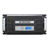
AE Techron 2120 Step-By-Step Manual (32 pages)
multi-amp system
Brand:
AE Techron
| Category:
Amplifier
| Size: 1.58 MB
Table of Contents
Table of Contents
2
1 Multi-Amp Systems Using 2100 or 7000 Series Amplifiers
4
Safety First
4
Overview
4
Multi-Amp Configuration Accessories
4
Figure 1.1 - Maximum Continuous Output in 7000-Series Multi-Amp Systems
4
Accessory Recommendations by System Type
5
2 Multi-Amp System Principles
6
One Master Amplifier for Series Systems
6
All Master Amplifiers for Parallel Systems
6
Use Only 7000-Series Amplifiers of the same Model Number
6
Use Correct Wiring
6
When Constructing Output Wiring, Use These Basic Criteria
6
Operate with Safety in Mind
6
3 Series Systems Configuration and Wiring
7
Choosing Single-Ended or Differential Configuration for Two-Amplifier Systems
7
Configure SIM-BNC-OPTOC Input Cards
7
Figure 3.1 - Two in Series: Single-Ended Vs. Differential
7
Figure 3.2 - SIM-BNC-OPTOC Card Jumper Locations
7
Install SIM-BNC-OPTOC Input Cards in Amplifiers
8
Configure Amplifiers' Main Boards for Slave Operation
8
Remove Output Terminal Resistor
9
Attach Master/Slave Labels (Optional)
9
Figure 3.3 - 7224 Amplifier Access Panel Screw Locations
9
Figure 3.4 - Master/Slave Jumper Locations
9
Figure 3.5 - 7224 Output Terminal Resistor
9
Figure 3.6 - 7548/7796 Output Terminal Resistor
9
Series System Wiring
10
Two in Series - Differential
10
Figure 3.7 - Terminating the Amplifier Input
10
Figure 3.8 - Verifying DC Offset
11
Figure 3.9 - Verifying Amp Gain
11
Figure 3.10 - Verifying System Gain
12
Figure 3.11 - Two Amplifiers in Series - Differential Configuration
12
Two or Three in Series - Single Ended
13
Figure 3.12 - Terminating the Amplifier Input
13
Figure 3.14 - Verifying Amp Gain
14
Figure 3.13 - Verifying DC Offset
14
Figure 3.15 - Verifying System Gain
15
Figure 3.16 - Two Amplifiers in Series - Single-Ended Configuration
15
Figure 3.17 - Three Amplifiers in Series - Single-Ended Configuration
16
4 Parallel Systems Configuration, Wiring and Balancing
17
Install Ballast Resistors
17
Figure 4.1 - 7224 Ballast Resistor Mounting
17
Figure 4.2 - 7796 Ballast Resistor Mounting
17
Figure 4.3 - 7224 Ballast Resistor Connected to Output Terminal
17
Figure 4.4 - 7796 Ballast Resistors Connected to Output Terminal
17
Main Board Access
18
Disable Gain Controls (7224 Amplifiers Only)
18
Figure 4.5 - Access Panel Screw Locations
18
Figure 4.6 - Gain Control Connection on Main Board
18
Parallel System Balancing
19
Connect for Balancing
19
Figure 4.7 - Gain Control Pin Settings
19
Figure 4.8 - Connecting for Balancing (Four in Parallel Shown)
19
Verify Interlock Operation
20
Adjust DC Offset
20
Wire and Connect Parallel Inputs
20
Figure 4.9 - Terminating the Amplifier Input
20
Figure 4.10 - Main Board Balancing Control Locations
20
Verify and Adjust Amplifier Gain
21
Figure 4.11 - Wiring and Test Points for DC Offset
21
Figure 4.12 - Wiring the Paralleled Input Wire
21
Figure 4.13 - Optional BNC Parallel Input Wiring (Three in Parallel Shown)
21
Amplifier Gain Matching
22
Figure 4.14- Wiring and Test Points for Amp Gain
22
Figure 4.15- Wiring and Test Points for Gain Matching
23
Verify Minimal Circulating Currents
24
Verify Current Sharing
24
Figure 4.16 - Two Amplifiers Paralleled
24
Figure 4.17 - Three Amplifiers Paralleled
25
Figure 4.18 - Four Amplifiers Paralleled
26
Appendix A Wire Current-Carrying Capacity
27
Figure A-1 - Wire Current-Carrying Capacity Chart
27
Appendix B Critical Wire Lengths in Parallel Systems
28
Figure B-1 - Critical Wire Lengths in Parallel Systems
28
Appendix C Building Parallel System Output Cables
29
Figure C-1 - Output Cables Constructed for Use in a Two-In-Parallel System
29
Appendix D Building the DB-25 Interlock Cable
30
Figure D-1 - DB-25 Cable Wiring for a Four-In-Parallel System
30
Appendix E Returning Slave Amplifiers to Stand-Alone Use
31
Figure E-1 - 7224 Access Panel Screw Locations
31
Figure E-2 - Master/Slave Jumper Locations
31
Figure E-3 - Output Terminal Resistor
31
Figure E-4 - 7548/7796 Output Terminal Resistor
31
Figure E-5 - SIM-BNC-OPTOC, Factory Default Settings
32
Advertisement
Advertisement
Related Products
AE Techron 2100 series
AE TECHRON 2105
AE Techron 2110
AE Techron 7000 Series
AE Techron 7000-Series
AE Techron 7212
AE Techron 7224
AE Techron 7226
AE Techron 7548
AE Techron 7794
AE Techron Categories
Amplifier
Portable Generator
Transformer
Inverter
More AE Techron Manuals
Login
Sign In
OR
Sign in with Facebook
Sign in with Google
Upload manual
Upload from disk
Upload from URL