Sign In
Upload
Manuals
Brands
Advantech Manuals
Motherboard
PCM-9386
Advantech PCM-9386 Manuals
Manuals and User Guides for Advantech PCM-9386. We have
2
Advantech PCM-9386 manuals available for free PDF download: User Manual, Startup Manual
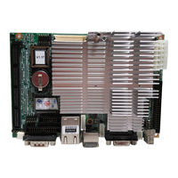
Advantech PCM-9386 User Manual (118 pages)
Celeron M 3.5" SBC with MIO/ VGA/LCD/LVDS Ethernet/USB2.0 and SSD
Brand:
Advantech
| Category:
Motherboard
| Size: 3.68 MB
Table of Contents
Packing List
3
Table of Contents
7
General Information
13
Chapter 1 Introduction
14
Introduction
14
Features
14
Specifications
15
Standard 3.5" Biscuit SBC Functions
15
VGA/LVDS Interface
15
Ethernet Interface
16
Audio Function
16
Mechanical and Environmental
16
Board Layout: Dimensions
17
Figure 1.1:Board Layout: Dimensions(Component Side)
17
Figure 1.2:Board Layout: Dimensions(Solder Side)
18
Chapter 2 Installation
20
Jumpers
20
Table 2.1:Jumpers
20
Jumper Location
20
Jumper Settings
21
Table 2.7:CMOS Clear (S2)
22
Connectors
23
Table 2.8:Connectors
23
Locating Connectors
24
Figure 2.1:Connectors (Component Side)
24
Figure 2.2:Connectors (Solder Side)
25
Setting Jumpers
26
Installing SO-DIMM
27
IDE, CDROM Hard Drive Connector (CN6)
27
Connecting the Hard Drive
28
Solid State Disk
28
Compactflash (CN21)
28
Floppy Disk Drive Connector (CN20)
28
Connecting the Floppy Disk Drive
28
Parallel Port Connector (CN13)
29
Keyboard and PS/2 Mouse Connector (CN14)
29
Power & HDD LED Connector(CN10)
30
Power Reset Button (S2)
30
Power Connectors (CN3)
30
Main Power Connector, +5 V, +12 V (CN3)
30
Fan Power Supply Connector (CN15)
30
Audio Interfaces (CN2)
30
Audio Connector (CN2)
30
COM Port Connector (CN8,CN19)
30
COM2 RS-232/422/485 Setting (J3/J4/J5)
31
Table 2.9: J3/J4/J5: COM2 RS-232/422/485 Select
31
VGA/LCD/LVDS Interface Connections
31
CRT Display Connector (CN18)
31
LVDS LCD Panel Connector (CN1)
31
Ethernet Configuration
31
100Base-T/1000Base-T Connector (CN12)
31
Network Boot(Depends on Ethernet Controller)
31
Watchdog Timer Configuration
32
USB Connectors (CN5,CN9)
32
GPIO (General Purpose Input Output) (CN7)
32
MIO Connector (CN4)
32
Chapter 3 Chipset Software Installation Utility
34
Before You Begin
34
Introduction
34
Installing the CSI Utility
35
Chapter 4 Award BIOS Setup
40
Introduction
40
CMOS RAM Auto-Backup and Restore
40
Entering Setup
41
Figure 4.1:Award BIOS Setup Initial Screen
41
Standard CMOS Setup
42
Figure 4.2:Standard CMOS Features Screen
42
Advanced BIOS Features
42
Figure 4.3:Advanced BIOS Features Screen
43
Virus Warning
43
L1 & L2 Cache
43
Quick Power on Self Test
43
First/Second/Third/Other Boot Device
43
Swap Floppy Drive
43
Boot up Floppy Seek
44
Boot up Numlock Status
44
Gate A20 Option
44
Typematic Rate Setting
44
Typematic Rate (Chars/Sec)
44
Typematic Delay (Msec)
44
PCM-9386 User's Manual
44
Security Option
44
APIC Mode
44
MPS Version Control for os
45
Integrated Peripherals
45
IDE Master/Slave PIO/UDMA Mode
45
On-Chip Secondary PCI IDE
45
Figure 4.4:Integrated Peripherals
45
USB Controller
46
USB Keyboard/Mouse Support
46
AC97 Audio
46
Init Display First
46
Onboard LAN Control
46
IDE HDD Block Mode
46
Onboard FDC Controller
46
Onboard Serial Port
46
UART Mode Select
46
Rxd, Txd Active
46
UR2 Duplex Mode
47
Onboard Parallel Port
47
Parallel Port Mode
47
EPP Mode Select
47
ECP Mode Use DMA
47
Power Management Setup
48
Figure 4.5:Power Management Setup Screen
48
Power-Supply Type
48
ACPI Function
48
Power Management
48
Video off in Suspend
49
Modem Use IRQ
49
HDD Power down
49
Soft-Off by PWR-BTTN
49
CPU THRM-Throttling
49
Poweron by LAN
49
Poweron by Modem
49
Poweron by Alarm
49
Primary IDE 0 (1) and Secondary IDE 0 (1)
50
Fdd, Com, Lpt Port
50
Pci Pirq [A-D]
50
Pnp/Pci Configurations
50
Pnp os Installed
50
Figure 4.6:Pnp/Pci Configurations Screen
50
Reset Configuration Data
51
Resources Controlled by
51
PCI/VGA Palette Snoop
51
Password Setting
51
Save & Exit Setup
52
Exit Without Saving
52
Chapter 5 PCI SVGA/LCD Setup
54
Introduction
54
CMOS Setting for Panel Type
54
Display Type
54
Dual Independent Display
54
Connections to Two Standard Lcds
56
LG LM 150X06 (1024X768 LVDS LCD)
56
Table 5.1:Connections to Lcd/Flat Panel (CN1)
56
AU M170EG01 (1280X1024 TFT LCD @ 48Bit)
57
Table 5.2:Connections to AU M170EG01 (CN1)
57
Installation of the SVGA Driver
58
Installation of Windows 98/2000
58
Further Information
61
Chapter 6 Audio Setup
64
Introduction
64
Driver Installation
64
Before You Begin
64
Windows 98 Drivers
65
Chapter 7 Ethernet Interface
68
Introduction
68
Installation of Ethernet Driver
68
Installation for Windows 98
68
Installation for Windows 2000
72
Further Information
77
Chapter 8 Installing MIO Modules
80
MIO Introduction
80
The Best Flexibility Interface in the Embedded App
80
A SBC Short Cut to System Design-Win
80
The Best Board Combination for a System
80
Optional Modules
80
MIO Module W/3 Fast Ethernet with by Pass
80
MIO Module for 6 COM Port
81
MIO-254 MIO Module for DVO to DVI/Tv/Audio
81
Installing MIO Modules
81
MIO Drawings
82
Figure 8.1:MIO Module Mounting Diagram
83
Table 8.1:MIO Connectors
84
Appendix A Programming GPIO & Waterdog Timer
88
Supported GPIO Register
88
GPIO Registers
88
A.1.1 GPIO Registers
88
GPIO Example Program-1
89
A.2 Watchdog Programming
91
Watchdog Programming
91
Appendix B Pin Assignments
94
CPU Fan Power Connector (CN15)
94
Table B.1:IR Connector (CN15)
94
Audio Connector (CN2)
94
Table B.2:Audio Connector (CN2)
94
Main Power Connector (CN3)
95
Table B.3:Main Power Connector (CN3)
95
Keyboard and PS/2 Mouse Connector (CN14)
95
Table B.4:Keyboard and Mouse Connector (CN14)
95
Floppy Disk Drive Connector (CN20)
96
Table B.5:Floppy Disk Drive Connector (CN20)
96
IDE Hard Drive Connector (CN6)
97
Table B.6:IDE HDD Connector (CN6)
97
Parallel Port Connector (CN13)
98
Table B.7:Parallel Port Connector (CN13)
98
Power & HDD LED Connector (CN10)
99
Table B.8:Power & HDD LED Connector (CN10)
99
USB Connector (CN5)
99
Table B.9:USB Connector (CN5)
99
LCD Inverter Backlight Connector (CN17)
100
Table B.10:LCD Inverter Backlight Conn (CN17)
100
LVDS Connector (CN1)
101
Table B.11:LVDS Connector (CN1)
101
COM2 RS232/422/485 Series Port (CN8)
102
Table B.12:COM2 RS-232/422/485 Series Port
102
Compactflash Card Connector (CN21)
102
Table B.13:Compactflash Card Connector (CN21)
102
IR Connetor (CN11)
103
B.14 IR Connetor (CN11)
103
Table B.14:IR Connector (CN11)
103
MIO Interface (CN4)
104
Table B.15:MIO Connectors
104
Appendix C System Assignments
108
System I/O Ports
108
C.1 System I/O Ports
108
Table C.1:System I/O Ports
108
1St MB Memory Map
109
DMA Channel Assignments
109
Table C.2:1St MB Memory Map
109
Table C.3:DMA Channel Assignments
109
C.4 Interrupt Assignments
110
Interrupt Assignments
110
Table C.4:Interrupt Assignments
110
Appendix D AT/ATX Power Setting
112
D.1 Introduction
112
Table D.1:Power Connector
112
Appendix E Mechanical Drawings
116
E.1 Mechanical Drawings
116
Figure E.2:PCM-9380/9386 Mech Drawing (Solder)
117
Advertisement
Advantech PCM-9386 Startup Manual (5 pages)
Celeron M 3.5" SBC with MIO/VGA/LCD/LVDS Ethernet/USB2.0 and SSD
Brand:
Advantech
| Category:
Motherboard
| Size: 0.32 MB
Advertisement
Related Products
Advantech PCM-9387
Advantech PCM-9389
Advantech PCM-9342
Advantech PCM-9372
Advantech PCM-9362 Series
Advantech PCM-9365
Advantech PCM-9343
Advantech PCM-9362NC-S6A1E
Advantech PCM-9362N-S6A1E
Advantech PCM-9362D-S6A1E
Advantech Categories
Motherboard
Computer Hardware
Desktop
Touch Panel
Network Router
More Advantech Manuals
Login
Sign In
OR
Sign in with Facebook
Sign in with Google
Upload manual
Upload from disk
Upload from URL