Advantech PCM-3353 PC/104 CPU Module Manuals
Manuals and User Guides for Advantech PCM-3353 PC/104 CPU Module. We have 3 Advantech PCM-3353 PC/104 CPU Module manuals available for free PDF download: User Manual
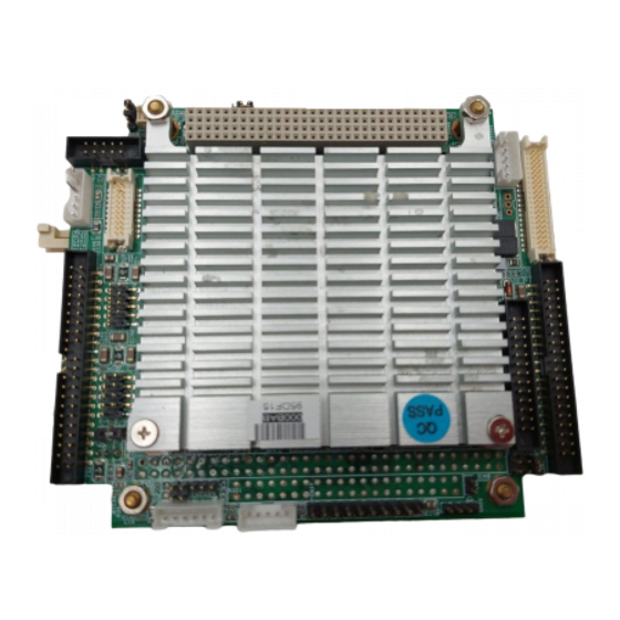
Advantech PCM-3353 User Manual (92 pages)
PC/104+ SBC w/AMD LX800, VGA, LCD, LAN, USB2.0 and CF
Brand: Advantech
|
Category: Motherboard
|
Size: 1 MB
Table of Contents
Advertisement

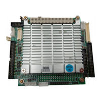
Advantech PCM-3353 User Manual (72 pages)
PC/104+ SBC w/AMD LX800/ LX600, VGA, LCD, LAN, USB2.0 and CF
Brand: Advantech
|
Category: Computer Hardware
|
Size: 24 MB
Table of Contents

Advantech PCM-3353 User Manual (72 pages)
PC/104+ SBC w/AMD LX800/ LX600, VGA, LCD, LAN, USB2.0 and CF
Brand: Advantech
|
Category: Computer Hardware
|
Size: 5 MB
Table of Contents
Advertisement