Sign In
Upload
Manuals
Brands
Advantech Manuals
PCI Card
PCI-1751U
Advantech PCI-1751U Manuals
Manuals and User Guides for Advantech PCI-1751U. We have
1
Advantech PCI-1751U manual available for free PDF download: User Manual
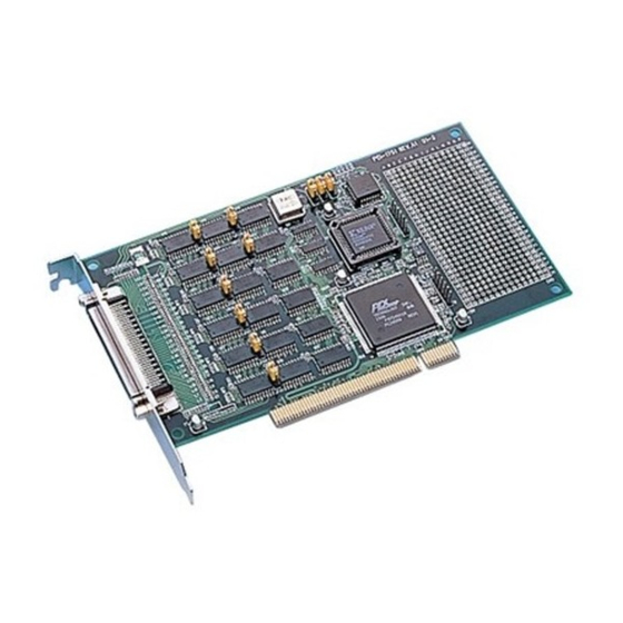
Advantech PCI-1751U User Manual (38 pages)
48-bit Digital Input/Output Card with Universal PCI Bus
Brand:
Advantech
| Category:
PCI Card
| Size: 0 MB
Table of Contents
Table of Contents
3
Chapter 1 General Information
6
Introduction
6
Numbering Convention
6
Features
6
Applications
7
Specifications
7
Input Signal
7
Output Signal
7
Interrupt Source
8
Transfer Rate
8
Chapter 2 Installation
10
Initial Inspection
10
Unpacking
10
Jumper Settings
11
Figure 2.1:Connectors & Jumpers
11
Set Ports as Input or Output by Software
11
Using Jumpers to Set Ports as Output Ports
12
Restore Ports to Condition Prior to Reset
12
Select Clock Source of Timers and Counter
13
Table 2.1:Jumper Settings
13
Setting the Boardid Switch (SW1)
14
Table 2.2:Boardid Setting (SW1)
14
Boardid Register
14
Table 2.3:Boardid Register
14
PCI-1751U Block Diagram
15
Figure 2.2:PCI-1751U Block Diagram
15
Pin Assignments
16
Installation Instructions
17
Chapter 3 Operation
20
Introduction
20
Digital I/O Ports
20
8255 Mode 0
20
Interrupt Function of the DIO Signals
21
Input/Output Control
21
Table 3.1:Bit Map of Port Configuration Register
21
Initial Configuration
21
Dry Contact Support for Digital Input
22
Figure 3.1:Wet & Dry Contact Inputs
22
Timer/Counter Operation
23
Introduction
23
Figure 3.2:Timer & Counter Structure
23
Timer 0 & 1: Two 16-Bit Timers or One 32-Bit Timer
23
Counter 2
24
Timer/Counter Frequency and Interrupt
24
Interrupt Function
25
Introduction
25
IRQ Level
25
Interrupt Control Register (Base + 32)
25
Table 3.2:Interrupt Control Register Bit Map
25
Interrupt Source Control
26
Figure 3.3:Figure 3-3: Interrupt Sources
26
Table 3.3:Interrupt Mode Bit Values
26
Interrupt Triggering Edge Control
27
Table 3.4:Triggering Edge Control Bit Values
27
Interrupt Flag Bit
27
Table 3.5:Interrupt Flag Bit Values
27
Appendix A Counter Chip Function
30
The Intel 8254
30
Counter Read/Write and Control Registers
30
Counter Operating Modes
33
MODE 0 - Stop on Terminal Count
33
MODE 1 - Programmable One-Shot
33
MODE 2 - Rate Generator
33
A.3.1 MODE 0 – Stop on Terminal Count
33
A.3.2 MODE 1 – Programmable One-Shot
33
A.3.3 MODE 2 – Rate Generator
33
MODE 3 - Square Wave Generator
34
MODE 4 - Software Triggered Strobe
34
MODE 5 - Hardware Triggered Strobe
34
A.3.4 MODE 3 – Square Wave Generator
34
A.3.5 MODE 4 – Software Triggered Strobe
34
A.3.6 MODE 5 – Hardware Triggered Strobe
34
Counter Operations
35
A.4 Counter Operations
35
Counter Latch Operation
35
Counter Read-Back Command
35
Read/Write Operation
35
Counter Applications
36
A.5 Counter Applications
36
Appendix B Register Format
38
Advertisement
Advertisement
Related Products
Advantech PCI-1751
Advantech PCI-1752U
Advantech PCI-1757UP
Advantech PCI-1752USO
Advantech PCI-1753
Advantech PCI-1753E
Advantech PCI-1755
Advantech PCI-1750
Advantech PCI-1752
Advantech PCI-1754
Advantech Categories
Motherboard
Computer Hardware
Desktop
Touch Panel
Network Router
More Advantech Manuals
Login
Sign In
OR
Sign in with Facebook
Sign in with Google
Upload manual
Upload from disk
Upload from URL