Sign In
Upload
Manuals
Brands
Advantech Manuals
Network Hardware
FWA-3260
Advantech FWA-3260 Network Appliance Manuals
Manuals and User Guides for Advantech FWA-3260 Network Appliance. We have
1
Advantech FWA-3260 Network Appliance manual available for free PDF download: User Manual
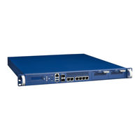
Advantech FWA-3260 User Manual (105 pages)
1U MIDDLE-RANGE NETWORK APPLIANCE BASED ON INTEL XEON D PROCESSORS SYSTEM ON CHIP
Brand:
Advantech
| Category:
Network Hardware
| Size: 5 MB
Table of Contents
Table of Contents
5
1 Getting Started
13
Safety Instructions
13
Safety Precautions Per IEC704-1
13
Safety Precautions - Static Electricity
14
Unpacking
14
Table 1: Packaging List
15
Installation and Configuration
16
Rack Mounting
16
Figure 1 : Mounting Ear Thread Holes
16
Figure 2: Mounting Ear Screws Inserted but Not Fastened yet
16
Powering on
17
Connecting to the Console
17
Figure 3: Putty Session Configuration
18
Figure 4: Putty Serial Configuration
18
Figure 5: Putty Keyboard Settings
19
Figure 6: Putty Colour Settings
19
Installing an os
20
Pre-Installed Reference os
20
Installing And/Or Boot an os from a USB Key
20
Figure 7: BIOS POST Screen (Example)
20
Installing an os Via Network Boot
21
Booting an os Via Network Boot
21
Table 2: PXE BIOS Options
22
Getting Help: Technical Support and Assistance
25
2 Product Specification
26
Overview
26
Product Versions
27
Figure 8: System Overview
27
Table 3: System Components
27
Table 4: Available Product Versions
27
Technical Specifications
28
Table 5: Specifications
29
Electromagnetic Compatibility
30
Figure 9: System Dimensions
30
Regulatory Compliance
30
Safety
30
System Dimensions
30
Table 6: Applicable Safety Regulations
30
CE Mark
31
Detailed Description
31
Front Elements
31
Figure 10: System Front View
31
Table 7: Applicable EMC Regulations
31
LED Details
32
Rear Elements
32
Figure 11: Front Leds
32
Figure 12: System Rear View
32
Table 8: Front Elements
32
Table 9: Rear Elements
32
System Block Diagram
33
Processor(S)
33
Figure 13: Block Diagram
33
Memory
34
Table 10: Xeon D Skus for Network and Enterprise Storage Infrastructure
34
Chipset
35
Usb
35
Figure 14: DIMM Location
35
Table 11: DIMM Mapping
35
Table 12: Validated Dimms
35
Table 13: USB Ports
35
Sata
36
Figure 15: M.2 SSD
36
Table 14: SATA Ports
36
Legacy Functions and IO
37
Table 15: Validated SATA Drives
37
Table 16: COM Ports
37
Network Interfaces (Onboard)
38
Pcie Expansion
38
Table 17: Smbus Devices
38
TPM Module
39
LCD Module
39
Mass Storage
39
Bios
40
Password Protection
40
Figure 16: Mass Storage Components
40
BIOS Defaults
41
Pcie Tree
41
Platform Management
42
Table 18: Pcie Devices
42
Figure 17: Thermal Sensor Locations
44
Figure 19: Display of CPU Temperature
44
Power Supplies
45
Product Labelling
45
Figure 18: Type Label (Bottom)
45
Table 20: Thermal Sensors
45
Figure 19: Product Labels (Internal)
46
Electronic Label: FRU EEPROM
47
Table 21: Product Labels
47
Table 22: FRU Data Synced to the DMI Tables
47
Advanced Platform Features
48
Intrusion Detection
48
Watchdog
48
LAN Bypass
48
Figure 20: Connectivity Options of LAN Ports in a Bypass Segment
48
LAN Bypass Segments
49
Bypass Watchdog Support
49
LED Behaviour
49
Figure 21: Onboard LAN Ports and Bypass Segments
49
Available Accessories and Related Products
50
Accessories
50
Table 23: Bypass States and LED Behaviour
50
Table 24: Accessories
50
3 Configuration and Service
51
Jumper Settings
51
Bios Setup Menu
51
Figure22: BIOS POST Screen (Example)
51
Figure 23: BIOS Setup Screen Organization
52
Figure 24: BIOS Setup Main Screen
52
Main Setup Menu
52
Setting System Time and Date
53
Table 25: BIOS Setup: Main Menu
53
Figure25: Platform Setup Main Screen
54
Platform Setup Menu
54
Serial Port Console Redirection
54
Figure 26: Platform Setup: Console Redirection Menu
55
Table 26: Platform Setup: COM1 Console Redirection Menu Items
56
USB Configuration
56
Figure 27: Platform Setup: USB Configuration Menu
57
Figure 28: Platform Setup: Trusted Computing
58
Table 27: USB Configuration Menu
58
Table 28: Trusted Computing Menu
58
Trusted Computing
58
Figure 29: Platform Setup: Trusted Computing with TPM2.0
59
Figure 30: Platform Setup: H/W Monitor
60
H/W Monitor
60
Table 29: Trusted Computing Menu with TPM2.0
60
Virtualization
60
Figure 31: Platform Setup: Virtualization
61
Platform Management
61
Table 30: Virtualization Menu
61
Figure 32: Platform Setup: Platform Management
62
Hardware
63
Table 31: Platform Management Menu
63
Figure 33: Hardware Configuration Menu
64
Hardware Setup: CPU Configuration
64
Figure 34: Chipset: Processor Configuration Menu
65
Table 32: Processor Configuration Menu
65
Figure 35: Northbridge Configuration Menu
66
Hardware Setup: North Bridge Configuration
66
Figure 36: Hardware Setup: PCI Subsystem
67
PCI Express Port Configuration
67
Table 33: Northbridge Configuration Menu
67
QPI Configuration
68
Table 34: Hardware Setup: PCI Subsystem Menu Items
68
Figure 37: Hardware Setup: QPI Configuration
69
Table 35: Hardware Setup: QPI Configuration Menu Items
69
Figure 38: Hardware Setup: South Bridge Configuration
70
Hardware Setup: South Bridge Configuration
70
Figure 39: Hardware Setup: SATA Configuration
71
Table 36: Hardware Setup: South Bridge Configuration Menu Items
71
Table 37: Hardware Setup: SATA Configuration Menu Items
71
ACPI Setting
72
Figure 40: Hardware Setup: USB Configuration
72
Table 38: Hardware Setup: USB Configuration Menu Items
72
USB Configuration
72
Figure 41: Hardware Setup: ACPI Configuration
73
Runtime Error Logging
73
Table 39: Hardware Setup: ACPI Configuration Menu Items
73
Figure 42: Hardware Setup: Runtime Error Logging Configuration
74
Server Mgmt
74
Table 40: Hardware Setup: Runtime Error Logging Menu Items
74
Figure 43: Server Mgmt Configuration
75
Table 41: Server Mgmt Configuration Menu Items
75
POST & Boot Menu
76
Security Setup
76
Figure 44 Boot Configuration
77
Table 42 Boot Configuration
77
Compatibility Support Module (CSM) Configuration
78
Figure 45: Post & Boot Setup: CSM Configuration Menu
78
Table 43: CSM Configuration Menu
78
Figure 46: Save & Exit Menu
79
Save & Exit Menu
79
Installing Components
80
Removing the Top Cover
80
Figure 47: Top Cover Screw Locations ( Left/Rear/Right)
80
Table 44: Save & Exit Menu Options
80
Reinstalling the Top Cover
81
Disk Installation
81
HDD Drive
81
Figure 48: Slide Top Cover Back
81
Figure 49: Top Cover Flange Disengagement
81
Figure 50: Screws for HDD Mounting
81
Figure 51: HDD Carrier Plate Dampeners
82
Figure 52: Carrier Plate and HDD Alignment
82
Figure 53: Screw Insertion and Fastening
83
Figure 54: HDD Carrier Plate Screw Locations
83
Figure 55: Insertion of the Carrier into the Chassis
84
Figure 56: SATA Cabling
85
Figure 57: SATA Connector Keying
85
Ssd
86
Figure 58: HDD Power Cable
86
Figure 59: M.2 SSD Mounting Screw
86
Memory Installation
87
Figure 60: M.2 SSD Key Alignment
87
Figure 61: M.2 SSD Angled Insertion
87
Figure 62: M.2 SSD Mounting
87
Figure 63: Opening DIMM Latches
88
Figure 64: DIMM Key Alignment
88
Figure 65: DIMM Insertion into Slide Rails
89
Figure 66: Seating the DIMM in the Socket
89
Firmware Upgrades
90
Bios
90
LAN Bypass
90
Replacing Frus
90
Disk Drives
90
Hdd
91
Ssd
91
CMOS Battery
91
Dimms
92
Figure 67: Unlocking the Battery
92
Figure 68 Battery Polarity
92
Figure 69: Unlocking and Removing a DIMM
93
Appendix: Connector Pinout and Led Information
94
Figure 70: RJ45 Console Connector
94
Table 45: Console Connector Pin Assignment
94
Figure 71: Stacked USB Type a Connector
95
Figure 72: RJ45 10/100/1000 Base-T Connector
95
Table 46: Stacked USB Type a Connector Pin Assignment
95
Table 47: RJ45 10/100/1000 Base-T Connector Pin Assignment
96
Table 48: RJ45 Connector LED Indication
96
Bios Post Codes
97
Table 49: BIOS POST Codes
102
Appendix: Power Supply Specification
103
Table 50: Single AC Power Supply Specification
103
Appendix: Declaration of Conformity
104
Appendix: Warranty and Rma
105
Advertisement
Advertisement
Related Products
Advantech FWA-3232
Advantech FWA-3051
Advantech FWA-3034
Advantech FWA-5020
Advantech FWA-6070
Advantech FWA-6172
Advantech FWA-5072-00A1R
Advantech FWA-6171
Advantech FWA-1320
Advantech FWA-T011
Advantech Categories
Motherboard
Computer Hardware
Desktop
Touch Panel
Network Router
More Advantech Manuals
Login
Sign In
OR
Sign in with Facebook
Sign in with Google
Upload manual
Upload from disk
Upload from URL