Sign In
Upload
Manuals
Brands
Advantech Manuals
Server Board
ASMB-781
Advantech ASMB-781 Manuals
Manuals and User Guides for Advantech ASMB-781. We have
2
Advantech ASMB-781 manuals available for free PDF download: User Manual, Startup Manual
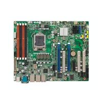
Advantech ASMB-781 User Manual (92 pages)
LGA1155 Intel Xeon E3/ Core i3 ATX Server Board with 2 PCIe x16 Expansion Slots
Brand:
Advantech
| Category:
Server Board
| Size: 5 MB
Table of Contents
Declaration of Conformity
4
Table of Contents
7
Chapter 1 Hardware Configuration
11
Introduction
12
Features
12
Specifications
12
System
12
Memory
13
Input/Output
13
Graphics
13
Ethernet LAN
13
Industrial Features
13
Mechanical and Environmental Specifications
13
Jumpers and Connectors
14
Table 1.1: Jumper List
14
Table 1.2: Connector List
14
Board Layout: Jumper and Connector Locations
16
Figure 1.1 Jumper and Connector Locations
16
Figure 1.2 I/O Connectors
16
ASMB-781 Block Diagram
17
Figure 1.3 ASMB-781 Block Diagram
17
Safety Precautions
17
Jumper Settings
18
How to Set Jumpers
18
CMOS and ME Clear (JCMOS1, JMECLR1)
18
Table 1.4: JME1
19
Watchdog Timer Output (JWDT1)
19
Table 1.5: Watchdog Timer Output (JWDT1)
19
Table 1.6: ME Update (JGREEN1)
19
Table 1.7: USB Power Switch (JUSB_1, JUSB_2)
19
Table 1.8: (CPUFAN_SEL1, SYSFAN_SEL1)
20
Table 1.9: ATX/AT Mode Selector (PSON1)
20
Table 1.10: Pcie X16 Slot Switch (JCFG1)
20
System Memory
20
Memory Installation Procedures
21
Cache Memory
21
Processor Installation
21
PCI Bus Routing Table
21
Chapter 2 Connecting Peripherals
23
Introduction
24
Parallel Port (LPT1)
24
USB Ports (LAN1_USB12, LAN2_USB3/4, USB5/6, USB7/8, USB9/10, USB11/12)
25
USB Power Switch
26
VGA Connector (VGA1)
27
Serial Ports (COM1, COM2)
27
PS/2 Keyboard and Mouse Connector (KBMS1)
28
External Keyboard & Mouse (KBMS2)
28
CPU Fan Connector (CPUFAN1)
29
System FAN Connector (SYSFAN1 through 4)
29
Front Panel Connectors (JFP1)
30
Power LED (JFP1)
30
Table 2.1: PS/2 or ATX Power Supply LED Status
30
External Speaker (JFP1 Pins 10, 12, 14, 16)
30
HDD LED Connector (JFP1 Pins 5 & 7)
30
ATX Soft Power Switch (JFP1 Pins 1 & 3)
31
Reset Connector (JFP1 Pins 2 & 4)
31
8-Pin Alarm Board Connector (VOLT1)
31
Case Open Connector (JFP1 Pin 6 & 8)
32
Front Panel LAN Indicator Connector (LANLED1 and LANLED2)
32
Serial ATA Interface (SATA1, SATA2, SATA3, SATA4, SATA5 & SATA6)
33
PCI Slots (PCI 1,2,5)
34
Pcie X16 Expansion Slot (PCIE4 and PCIE6)
34
Pciex4_1
35
Pciex1_1
35
Auxiliary 8-Pin Power Connector (ATX8P_P1)
36
SPI Flash Connector(SPI_CN1)
36
Low Pin Count Connector (LPC1)
37
Table 2.3: Advantech LPC Module List
37
BIOS Operation
39
Chapter 3 BIOS Operation
39
Figure 3.1 Main Setup Screen
40
Introduction
40
Entering BIOS Setup
40
Main Menu
41
Figure 3.2 Main Setup Screen
41
System Time / System Date
41
Advanced BIOS Features Setup
42
Figure 3.3 Advanced BIOS Features Setup Screen
42
PCI Subsystem Settings
43
Figure 3.4 PCI Subsystem Settings Screen
43
ACPI Settings
44
Figure 3.5 ACPI Settings
44
Trusted Computing
45
Figure 3.6 TPM Settings
45
CPU Configuration
46
Figure 3.7 CPU Configuration
46
SATA Configuration
47
Figure 3.8 SATA Configuration
47
Intel TXT(LT) Configuration
48
Figure 3.9 Intel Trusted Execution Technology Configuration
48
USB Configuration
49
Figure 3.10USB Configuration
49
NCT6776 Super IO Configuration
50
Figure 3.11Super IO Configuration
50
Figure 3.12Serial Port 1 Configuration
50
Figure 3.13Serial Port 2 Configuration
51
Figure 3.14Parallel Configuration
51
H/W Monitor
52
Figure 3.15PC Health Status
52
Serial Port Console Redirection
53
Figure 3.16Serial Port Console Redirection
53
Chipset
56
Figure 3.17Chipset
56
North Bridge
56
Figure 3.18North Bridge
56
South Bridge
57
Figure 3.19South Bridge
57
LAN Configuration
58
Figure 3.20LAN Configuration Screen
58
Figure 3.21USB Configuration
59
USB Configuration
59
Boot
60
Figure 3.22Boot
60
Security
61
Figure 3.23Security
61
Save & Exit
62
Figure 3.24Save & Exit
62
Chapter 4 Chipset Software Installation Utility
63
Before You Begin
64
Introduction
64
Windows XP / Windows 7 Driver Setup
65
Chapter 5 VGA Setup
67
Introduction
68
Windows Xp/Windows 7 Driver Setup
68
Chapter 6 LAN Configuration
69
Introduction
70
Features
70
Installation
70
Win XP /Win 7 Driver Setup (LAN)
70
Watchdog Timer Overview
72
Programming the Watchdog Timer
72
Example Programs
74
Table A.1: Watchdog Timer Registers
74
A.2.1 Example Programs
74
Parallel Port (LPT1)
80
Table B.1: Parallel Port (LPT1)
80
USB Header (USB56, USB78, USB910)
80
Table B.2: USB Header
80
VGA Connector (VGA1)
81
RS-232 Interface (COM2)
81
Table B.4: RS-232 Interface (COM1)
81
PS/2 Keyboard and Mouse Connector (KBMS1)
82
Table B.5: Keyboard and Mouse Connector (KBMS1)
82
External Keyboard Connector (KBMS2)
82
Table B.6: External Keyboard Connector (KBMS2)
82
System Fan Power Connector (SYSFAN1~4)
83
Table B.7: Fan Power Connector (SYSFAN1/SYSFAN2)
83
Power LED (JFP1)
83
Table B.8: Power LED (JFP1)
83
External Speaker Connector (JFP1)
83
Table B.9: External Speaker Connector (JFP1)
83
Reset Connector (JFP1)
84
Table B.10:Reset Connector (JFP1)
84
HDD LED Connector (JFP1)
84
ATX Soft Power Switch (JFP1)
84
Table B.11:HDD LED Connector (JFP1)
84
Front Panel Smbus Connector (FP_SMB1)
84
B.13 Front Panel Smbus Connector (FP_SMB1)
84
Table B.12:ATX Soft Power Switch (JFP1)
84
Table B.13:Front Panel Smbus Connector(FP_SMB1)
84
B.14 USB/LAN Ports (LAN1_USB12 and LAN2_USB34)
85
Table B.14:USB Port
85
Table B.15:Giga LAN 10/100/1000 Mbps RJ-45 Port
85
Front Panel Audio Connector (FPAUD1)
86
Table B.16:Front Panel Audio Connector (FPAUD1)
86
8-Pin Alarm Board Connector (VOLT1)
86
Table B.17:8-Pin Alarm Board Connector (VOLT1)
86
Case Open Connector (JFP1)
86
Table B.18:Case Open Connector (JFP1)
86
Front Panel LAN LED Connector (LAN_LED1/2)
87
B.18 Front Panel LAN LED Connector (LAN_LED1/2)
87
SPI_CN1: SPI Flash Card Pin Connector
87
Table B.19:LAN LED Connector (LAN_LED1/2)
87
System I/O Ports
87
Table B.20:SPI_CN1:SPI Fresh Card Pin Connector
87
B.20 System I/O Ports
87
Table B.21:System I/O Ports
87
DMA Channel Assignments
88
Interrupt Assignments
88
Table B.22:DMA Channel Assignments
88
B.22 Interrupt Assignments
88
Table B.23:Interrupt Assignments
88
1St MB Memory Map
89
Table B.24:1St MB Memory Map
89
Advertisement
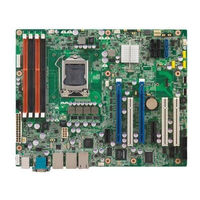
Advantech ASMB-781 Startup Manual (3 pages)
Intel Xeon E3/ Core i3 Single 1155 Socket ATX Server Board with 2 PCIe x16 Expansion Slots
Brand:
Advantech
| Category:
Server
| Size: 0 MB
Table of Contents
Ethernet Interface
1
Packing List
1
Standard SBC Functions
1
Jumpers and Connectors
2
Jumper List
2
Connector List
2
Installation Note
3
Software Installation
3
Declaration of Conformity
3
Board Layout
3
Advertisement
Related Products
Advantech ASMB-784
Advantech ASMB-782G2-00A1E
Advantech ASMB-782G4-00A1E
Advantech ASMB-813I Series
Advantech ASMB-825-00A1E
Advantech ASMB-260T2-22A1
Advantech ASMB-260I-22A1
Advantech ASMB-260I-21A1
Advantech ASMB-922I-00A1E
Advantech ASMB-922-00A1E
Advantech Categories
Motherboard
Computer Hardware
Desktop
Touch Panel
Network Router
More Advantech Manuals
Login
Sign In
OR
Sign in with Facebook
Sign in with Google
Upload manual
Upload from disk
Upload from URL