Sign In
Upload
Manuals
Brands
Advantech Manuals
Motherboard
AIMB-767
User Manuals: Advantech AIMB-767 Motherboard Industrial
Manuals and User Guides for Advantech AIMB-767 Motherboard Industrial. We have
1
Advantech AIMB-767 Motherboard Industrial manual available for free PDF download: User Manual
Advantech AIMB-767 User Manual (86 pages)
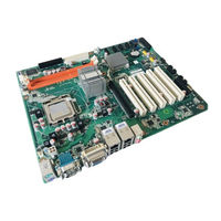
Socket LGA 775 Intel Core 2 Quad/Core 2 Duo/Intel Pentium/Celeron FSB 1333 MHz Processor-based ATX Motherboard with VGA/DVI, 4 COM, and Dual LAN
Brand:
Advantech
| Category:
Motherboard
| Size: 4 MB
Table of Contents
Safety Information
2
Declaration of Conformity
4
Ordering Information
7
Table of Contents
9
Chapter 1 General Information
13
Introduction
14
Features
14
Specifications
14
System
14
Memory
14
Input/Output
14
Graphics
15
Ethernet LAN
15
Industrial Features
15
Mechanical and Environmental Specifications
15
Jumpers and Connectors
15
Table 1.1: Jumpers
15
Table 1.2: Connectors
16
Board Layout: Jumper and Connector Locations
17
Figure 1.1 Jumper and Connector Location
17
Figure 1.2 I/O Connectors
17
AIMB-767 Block Diagram
18
Figure 1.3 AIMB-767 Block Diagram
18
Safety Precautions
19
Jumper Settings
20
How to Set Jumpers
20
CMOS Clear (JCMOS1)
20
Table 1.3: CMOS1
20
Chassis Instruction Connector (JCASE1)
20
ATX/AT Mode Selector (PSON1)
20
Table 1.4: ATX/AT Mode Selector (PSON1)
20
COM3 RS-232/422/485 Mode Selector (JSETCOM3)
21
Table 1.5: COM3 RS-232/422/485 Mode Selector (JSETCOM3)
21
System Memory
21
Memory Installation Procedures
21
Cache Memory
22
Processor Installation
22
Chapter 2 Connecting Peripherals
23
Introduction
24
Parallel Port (LPT1)
24
USB Ports (LAN1_USB12/LAN2_USB34/USB56/USB78)
25
Table 2.1: LAN LED Indicator
25
VGA Connector (VGA1)
26
Serial Ports (COM1~COM4)
26
PS/2 Keyboard and Mouse Connector (KBMS1)
27
CPU Fan Connector (CPUFAN1)
28
System FAN Connector (SYSFAN1/2)
28
Front Panel Connectors (JFP1/2/3)
29
ATX Soft Power Switch (JFP1)
29
Reset Connector (JFP1)
29
External Speaker (JFP2)
30
HDD LED Connector (JFP2)
30
Smbus Connector (JFP2)
30
Power LED and Keyboard Lock Connector
31
Lock)
31
Line out and MIC in Connector (AUDIO1)
32
Serial ATA Interface (SATA 1/2/3/4)
32
ATX Power Connector (ATX12V1, EATXPWR1)
33
SPI Flash Connector (SPI_CN1)
34
Front Panel Audio Connector (FPAUD1)
34
DVI Connector(DVI1)
35
USB 2.0 Connector (USB 56, 78)
35
Digital Audio Connector(SPDIF_OUT1)
36
Connector to Alarm Board for Monitoring (VOLT1)
36
BIOS Operation
37
Chapter 3 BIOS Operation
37
Introduction
38
BIOS Setup
38
Main Menu
39
Advanced BIOS Features
40
CPU Configuration
40
IDE Configuration
41
Floppy Configuration
42
Super IO Configuration
43
Hardware Health Configuration
43
ACPI Setting
44
General ACPI Setting
45
Advanced ACPI Configuration
45
APM Configuration
46
Advanced Pci/Pnp Setting
47
Boot Setting
48
Boot Device Priority
49
Removable Drivers
49
Security Setting
49
Advanced Chipset Settings
50
North Bridge Chipset Configuration
50
South Bridge Chipset Configuration
51
Exit Option
52
Chapter 4 Chipset Software Installation Utility
55
Before You Begin
56
Introduction
56
Windows Xp/Windows 7 Driver Setup
57
VGA Setup
59
Chapter 5 VGA Setup
59
Introduction
60
Windows XP/7
60
LAN Configuration
61
Chapter 6 LAN Configuration
61
Introduction
62
Features
62
Installation
62
Windows XP/ Windows 7 Setup (Intel 82583V)
62
Appendix A Programming the Watchdog Timer
66
Programming the Watchdog Timer
66
Watchdog Timer Overview
66
Table A.1: Watchdog Timer Registers
68
Example Program
69
A.1.3 Example Program
69
Appendix B I/O Pin Assignments
73
Parallel Port (LPT1)
74
Table B.1: Parallel Port (LPT1)
74
USB Header (USB56)
74
Table B.2: USB Header (USB56)
74
USB Header (USB78)
75
Table B.3: USB Header (USB78)
75
VGA Connector (VGA1)
75
Table B.4: VGA Connector (VGA1)
75
RS-232 Interface (COM1-COM4)
76
Table B.5: RS-232 Interface (COM1~COM2)
76
RS-232/422/485 Setting Interface (JSETCOM3)
76
Table B.6: RS-232/422/485 Setting Interface (JSETCOM3)
76
SPI_CN1: SPI Fresh Card Pin Connector
77
Table B.7: SPI_CN1:SPI Fresh Card Pin Connector
77
PS/2 Keyboard and Mouse Connector (KBMS1)
77
Table B.8: PS/2 Keyboard and Mouse Connector (KBMS1)
77
CPU Fan Power Connector (CPU_FAN1)
78
System Fan Power Connector (SYS_FAN1/SYS_FAN2)
78
Front Panel Connectors (JFP1/2)
79
Power LED & Keyboard Lock Connector (JFP3)
79
Table B.11:Power LED & Keyboard Lock Connector (JFP3)
79
Power Switch/Hdd Led/Smbus/Speaker (JFP1/JFP2)
79
ATX1 12 V Auxiliary Power Connector (ATX12V1)
80
Table B.13:ATX1 12 V Auxiliary Power Connector (ATX12V1)
80
ATX Power Connector (EATXPWR1)
80
Table B.14:ATX Power Connector (ATX2)
80
USB/LAN Ports (LAN1/2_USB12/USB34)
81
Table B.15:USB Port
81
Table B.16:Ethernet 10/100/1000 Base-T RJ-45 Port
81
Line Out, MIC in Connector (AUDIO1)
81
Serial ATA0 (SATA1)
81
Table B.17:Serial ATA0 (SATA1)
81
Serial ATA1 (SATA2)
82
Table B.18:Serial ATA1 (SATA2)
82
Serial ATA2 (SATA3)
82
Table B.19:Serial ATA2 (SATA3)
82
Serial ATA3 (SATA4)
82
Table B.20:Serial ATA3 (SATA4)
82
AT/ATX Mode (PSON1)
82
Table B.21:AT/ATX Mode (PSON1)
82
Fpaud1(Front Panel Audio Connector)
83
System I/O Ports
83
Table B.22:Front Panel Audio Connector (FPAUD1)
83
B.22 System I/O Ports
83
Table B.23:System I/O Ports
83
Jcase1(Open Case Connector)
84
Table B.24:Case Open Connector(JCASE1)
84
DMA Channel Assignments
84
Table B.25:DMA Channel Assignments
84
Interrupt Assignments
84
Table B.26:Interrupt Assignments
84
St MB Memory Map
84
Table B.27:1St MB Memory Map
84
Advertisement
Advertisement
Related Products
Advantech AIMB-766
Advantech AIMB-760
Advantech AIMB-763
Advantech AIMB-764
Advantech AIMB-741 Series
Advantech AIMB-701 LGA1155
Advantech AIMB-781QVG
Advantech AIMB-741E2-00A1
Advantech AIMB-741G-00A1
Advantech AIMB-781QG2-00A1E
Advantech Categories
Motherboard
Computer Hardware
Desktop
Touch Panel
Network Router
More Advantech Manuals
Login
Sign In
OR
Sign in with Facebook
Sign in with Google
Upload manual
Upload from disk
Upload from URL