Sign In
Upload
Manuals
Brands
Advantech Manuals
Motherboard
AIMB-213
Advantech AIMB-213 Manuals
Manuals and User Guides for Advantech AIMB-213. We have
3
Advantech AIMB-213 manuals available for free PDF download: User Manual, Startup Manual
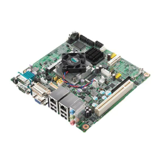
Advantech AIMB-213 User Manual (95 pages)
Intel Atom N455/D525 1.66/1.8 GHz Mini-ITX with VGA/DVI/LVDS, 6 COMs, Dual LANs, 8 USBs, Mini PCIe
Brand:
Advantech
| Category:
Motherboard
| Size: 4.84 MB
Table of Contents
User Manual
1
Declaration of Conformity
4
Ordering Information
6
Table of Contents
9
Chapter 1 General Information
13
Introduction
14
Features
14
Specifications
15
System
15
Memory
15
Input/Output
15
Graphics
15
Ethernet LAN
15
Industrial Features
15
Mechanical and Environmental Specifications
16
Jumpers and Connectors
16
Table 1.1: Jumpers
16
Table 1.2: Connectors
16
Board Layout: Jumper and Connector Locations
18
Figure 1.1 Jumper and Connector Location
18
Figure 1.2 I/O Connectors
18
AIMB-213 Board Diagram
19
Figure 1.3 AIMB-213 Board Diagram
19
Safety Precautions
20
Jumper Settings
21
How to Set Jumpers
21
CMOS Clear (CMOS1)
21
Table 1.3: CMOS1
21
COM2 RS 232/422/485 Mode Selector (JSETCOM2)
22
(Jsetcom2)
22
JLVDS1 and JLVDS2: LCD Power 3.3 V/5 V/ 12 V Selector
22
PSON1: ATX, at Mode Selector
23
Table 1.6: PSON1: ATX, at Mode Selector
23
JWDT1: Watchdog Timer Output Option
23
Table 1.7: JWDT1: Watchdog Timer Output Option
23
System Memory
24
Memory Installation Procedures
24
Chapter 2 Connecting Peripherals
25
Introduction
26
USB Ports (LAN1_USB12/LAN2_USB34/USB56/USB78)
26
Table 2.1: LAN LED Indicator
26
VGA Connector (VGA1)
27
Serial Ports (COM1~COM6)
28
PS/2 Keyboard and Mouse Connector (KBMS1)
29
CPU Fan Connector (CPU_FAN1)
29
System FAN Connector (SYSFAN1)
30
Front Panel Connectors (JFP1/JFP1+JFP2)
31
ATX Soft Power Switch ((JFP1+JFP2/ PWR_SW))
31
Reset (JFP1+JFP2/ RESET)
31
Hdd Led (Jfp1+Jfp2/ Hddled)
31
External Speaker (JFP1+JFP2/ SPEAKER)
31
Power LED and Keyboard Lock Connector
32
AT Power)
32
Key Lock)
32
Line In, Line Out, MIC in Connector (AUDIO1)
32
Serial ATA Interface (SATA1/2/3)
33
Pci
33
Front Headphone Connector (HD1)
34
ATX 12V Power Connector (ATX12V_1)
35
SPI Flash Connector(SPI_CN1)
35
LCD Inverter Connector (INV1)
36
LVDS Connector (LVDS1)
37
General Purpose I/O Connector (GPIO1)
37
BIOS Operation
39
Chapter 3 BIOS Operation
39
Introduction
40
BIOS Setup
40
Main Menu
41
Advanced BIOS Features
42
Advanced Pci/Pnp Settings
52
Boot Settings
54
Security Setup
55
Advanced Chipset Settings
56
Exit Option
59
Chapter 4 Software Introduction & Service
61
Introduction
62
Value-Added Software Services
62
Software API
62
Software Utility
64
Chapter 5 Chipset Software Installation Utility
65
Before You Begin
66
Introduction
66
Windows XP Driver Setup
67
VGA Setup
69
Chapter 6 VGA Setup
69
Introduction
70
Windows 7/Vista/Xp
70
LAN Configuration
71
Chapter 7 LAN Configuration
71
Introduction
72
Features
72
Installation
72
Windows 7/Vista/Xp Driver Setup (Intel 82567V/82583V)
73
Appendix A Programming the Watchdog Timer
75
Programming the Watchdog Timer
76
Watchdog Timer Overview
76
Table A.1: Watchdog Timer Registers
78
Example Program
79
A.1.3 Example Program
79
Appendix B I/O Pin Assignments
83
USB Header (USB56, USB78)
84
Table B.1: USB Header (USB56)
84
VGA Connector (VGA1)
84
Table B.2: VGA Connector (VGA1)
84
RS-232 Interface (COM3/4/5/6)
85
B.3 RS-232 Interface (COM3/4/5/6)
85
Table B.3: RS-232 Interface (COM3~COM6)
85
RS-232/422/485 Setting Interface (JSETCOM2)
86
Table B.4: RS-232/422/485 Setting Interface (JSETCOM2)
86
SPI_CN1: SPI Fresh Card Pin Connector
86
Table B.5: SPI_CN1:SPI Fresh Card Pin Connector
86
PS/2 Keyboard and Mouse Connector (KBMS1)
87
CPU Fan Power Connector (CPU_FAN1)
87
System Fan Power Connector (CHA_FAN1)
87
(Sysfan1/Sysfan2)
87
Table B.6: PS/2 Keyboard and Mouse Connector (KBMS1)
87
B.7 CPU Fan Power Connector (CPU_FAN1)
87
Table B.7: CPU Fan Power Connector (CPU_FAN1)
87
B.8 System Fan Power Connector (CHA_FAN1)
87
Power LED & Keyboard Lock Connector (JFP1)
88
Table B.9: Power LED & Keyboard Lock Connector (JFP1)
88
Power Switch/Hdd Led/Smbus/Speaker (JFP1+JFP2)
88
(Jfp1+Jfp2)
88
USB/LAN Ports (LAN1_USB12/LAN2_USB34)
89
B.11 USB/LAN Ports (LAN1_USB12/LAN2_USB34)
89
Table B.11:USB Port
89
Table B.12:Ethernet 10/100 Mbps RJ-45 Port
89
Line In, Line Out, MIC in Connector (AUDIO1)
89
Serial ATA0/1 (SATA1/2/3)
89
Table B.13:Serial ATA 0/1 (SATA1/2/3)
89
AT/ATX Mode (PSON1)
90
Table B.14:AT/ATX Mode (PSON1)
90
HD Audio Interface (HD1)
90
Table B.15:AC-97 Audio Interface (HD1)
90
GPIO Pin Header (GPIO1)
90
Table B.16:GPIO Pin Header (GPIO1)
90
LVDS Connector: LVDS1
91
Table B.17:LVDS1 Connector
91
LVDS Power Jumper (JLVDS1 and JLVDS2)
92
Table B.18:LVDS Power Jumper
92
LVDS Inverter (INV1)
92
Table B.19:LVDS Power Jumper
92
ATX 12 V Connector (ATX12V_1)
92
Table B.20:ATX 12 V Connector (ATX12V_1)
92
DMA Channel Assignments
93
Interrupt Assignments
93
B.22 Interrupt Assignments
93
Table B.21:DMA Channel Assignments
93
Table B.22:Interrupt Assignments
93
1St MB Memory Map
93
Table B.23:1St MB Memory Map
93
Advertisement
Advantech AIMB-213 User Manual (93 pages)
Intel Atom N455/D525 1.66/1.8 GHz Mini-ITX with VGA/DVI/LVDS, 6 COMs, Dual LANs, 8 USBs, Mini PCIe
Brand:
Advantech
| Category:
Motherboard
| Size: 2.93 MB
Table of Contents
Declaration of Conformity
4
Ordering Information
6
Table of Contents
9
Chapter 1 General Information
13
Introduction
14
Features
14
Specifications
15
System
15
Memory
15
Input/Output
15
Graphics
15
Ethernet LAN
15
Industrial Features
15
Mechanical and Environmental Specifications
16
Jumpers and Connectors
16
Board Layout: Jumper and Connector Locations
18
AIMB-213 Board Diagram
19
Safety Precautions
20
Jumper Settings
21
How to Set Jumpers
21
CMOS Clear (CMOS1)
21
COM2 RS 232/422/485 Mode Selector (JSETCOM2)
22
(Jsetcom2)
22
JLVDS1 and JLVDS2: LCD Power 3.3 V/5 V/ 12 V Selector
22
Selector
22
PSON1: ATX, at Mode Selector
23
JWDT1: Watchdog Timer Output Option
23
System Memory
24
Memory Installation Procedures
24
Chapter 2 Connecting Peripherals
25
Introduction
26
USB Ports (LAN1_USB12/LAN2_USB34/USB56/USB78)
26
VGA Connector (VGA1)
27
Serial Ports (COM1~COM6)
28
PS/2 Keyboard and Mouse Connector (KBMS1)
29
CPU Fan Connector (CPU_FAN1)
29
System FAN Connector (SYSFAN1)
30
Front Panel Connectors (JFP1/JFP1+JFP2)
31
ATX Soft Power Switch ((JFP1+JFP2/ PWR_SW))
31
Reset (JFP1+JFP2/ RESET)
31
Hdd Led (Jfp1+Jfp2/ Hddled)
31
External Speaker (JFP1+JFP2/ SPEAKER)
31
Power LED and Keyboard Lock Connector
32
Key Lock)
32
AT Power)
32
Line In, Line Out, MIC in Connector (AUDIO1)
32
Serial ATA Interface (SATA1/2/3)
33
Pci
33
Front Headphone Connector (HD1)
34
ATX 12V Power Connector (ATX12V_1)
35
SPI Flash Connector(SPI_CN1)
35
LCD Inverter Connector (INV1)
36
LVDS Connector (LVDS1)
37
General Purpose I/O Connector (GPIO1)
37
BIOS Operation
39
Chapter 3 BIOS Operation
39
Introduction
40
BIOS Setup
40
Main Menu
41
Advanced BIOS Features
42
Advanced Pci/Pnp Settings
52
Boot Settings
54
Security Setup
55
Advanced Chipset Settings
56
Exit Option
59
Chapter 4 Software Introduction & Service
61
Introduction
62
Value-Added Software Services
62
Software API
62
Software Utility
64
Chapter 5 Chipset Software Installation Utility
65
Before You Begin
66
Introduction
66
Windows XP Driver Setup
67
VGA Setup
69
Chapter 6 VGA Setup
69
Introduction
70
Windows 7/Vista/Xp
70
LAN Configuration
71
Chapter 7 LAN Configuration
71
Introduction
72
Features
72
Installation
72
Windows 7/Vista/Xp Driver Setup (Intel 82567V/82583V)
73
Appendix A Programming the Watchdog Timer
75
Programming the Watchdog Timer
76
Watchdog Timer Overview
76
Table A.1: Watchdog Timer Registers
78
Example Program
79
A.1.3 Example Program
79
Appendix B I/O Pin Assignments
83
USB Header (USB56, USB78)
84
VGA Connector (VGA1)
84
RS-232 Interface (COM3/4/5/6)
85
B.3 RS-232 Interface (COM3/4/5/6)
85
RS-232/422/485 Setting Interface (JSETCOM2)
86
SPI_CN1: SPI Fresh Card Pin Connector
86
PS/2 Keyboard and Mouse Connector (KBMS1)
87
CPU Fan Power Connector (CPU_FAN1)
87
System Fan Power Connector (CHA_FAN1)
87
(Sysfan1/Sysfan2)
87
Power LED & Keyboard Lock Connector (JFP1)
88
Power Switch/Hdd Led/Smbus/Speaker (JFP1+JFP2)
88
(Jfp1+Jfp2)
88
USB/LAN Ports (LAN1_USB12/LAN2_USB34)
89
Line In, Line Out, MIC in Connector (AUDIO1)
89
Serial ATA0/1 (SATA1/2/3)
89
B.11 USB/LAN Ports (LAN1_USB12/LAN2_USB34)
89
AT/ATX Mode (PSON1)
90
HD Audio Interface (HD1)
90
GPIO Pin Header (GPIO1)
90
LVDS Connector: LVDS1
91
LVDS Power Jumper (JLVDS1 and JLVDS2)
92
LVDS Inverter (INV1)
92
ATX 12 V Connector (ATX12V_1)
92
DMA Channel Assignments
93
Interrupt Assignments
93
1St MB Memory Map
93
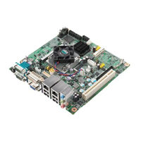
Advantech AIMB-213 Startup Manual (4 pages)
Intel Atom N455/D525 1.66/1.8 GHz Mini-ITX with VGA/DVI/LVDS, 6 COM, Dual LAN, 8 USB, Mini PCIe
Brand:
Advantech
| Category:
Motherboard
| Size: 0.43 MB
Advertisement
Advertisement
Related Products
Advantech AIMB-217
Advantech AIMB218L-S0A1E
Advantech AIMB-215L-S6B1E
Advantech AIMB-215D-S6B1E
Advantech AIMB-215N-S6B1E
Advantech AIMB-218ZS0A1E
Advantech AIMB-218JS0A1E
Advantech AIMB-218DS0A1E
Advantech AIMB-218 Series
Advantech AIMB-216
Advantech Categories
Motherboard
Computer Hardware
Desktop
Touch Panel
PCI Card
More Advantech Manuals
Login
Sign In
OR
Sign in with Facebook
Sign in with Google
Upload manual
Upload from disk
Upload from URL