Advanced Power technologies TTC-1000 Manuals
Manuals and User Guides for Advanced Power technologies TTC-1000. We have 2 Advanced Power technologies TTC-1000 manuals available for free PDF download: Instruction & Operation Manual
Advanced Power technologies TTC-1000 Instruction & Operation Manual (262 pages)
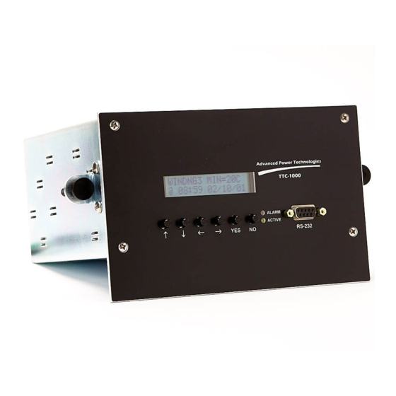
Transformer Temperature Controller
Brand: Advanced Power technologies
|
Category: Temperature Controller
|
Size: 2 MB
Table of Contents
-
Introduction12
-
-
Power Hookup23
-
-
-
-
Settings42
-
-
Probe Names56
-
-
-
-
View Settings126
-
Status134
-
-
Setting Files136
-
-
Data Logging142
-
Data Storage142
-
Data Points143
-
Import to Excel149
-
Advertisement
Advanced Power technologies TTC-1000 Instruction & Operation Manual (177 pages)
3 Probe Transformer Temperature Controller
Brand: Advanced Power technologies
|
Category: Temperature Controller
|
Size: 1 MB
Table of Contents
-
-
Mounting17
-
Power Hookup19
-
-
-
4 Settings
34 -
8 Status
96 -
10 Data Logging
113-
Data Storage113
-
Data Points114
-
Import to Excel125
-
Advertisement