Advanced Power technologies TTC-1000 Instruction & Operation Manual
Transformer temperature controller
Hide thumbs
Also See for TTC-1000:
- Instruction & operation manual (177 pages) ,
- Instruction & operation manual (191 pages)
Table of Contents
Advertisement
Quick Links
TTC-1000
Transformer Temperature Controller
Instruction & Operation Manual
1 - 3 Temperature Probes
4, 6, or 8 Outputs
9 CT Inputs
14 Digital Inputs
Tap Position Monitoring
Firmware version 6.23X
Advanced Power Technologies
215 State Route 10, Building 2
Randolph, NJ 07869
Phone: (973) 328-3300
Fax:
(973) 328-0666
Website: advpowertech.com
e-mail: info@advpowertech.com
(This manual applies to firmware versions 6.23X)
V6.230 20131017
Advertisement
Table of Contents

Related Manuals for Advanced Power technologies TTC-1000

Summary of Contents for Advanced Power technologies TTC-1000
- Page 1 4, 6, or 8 Outputs 9 CT Inputs 14 Digital Inputs Tap Position Monitoring Firmware version 6.23X Advanced Power Technologies 215 State Route 10, Building 2 Randolph, NJ 07869 Phone: (973) 328-3300 Fax: (973) 328-0666 Website: advpowertech.com...
-
Page 2: Table Of Contents
Table of Contents INTRODUCTION ...................1 PRODUCT DESCRIPTION................3 Controls & Indicators ................3 Connection Overview- Panel Mount Unit ..........4 Rear Layout- Panel Mount Unit ..............5 Connections Overview - NEMA Enclosure ..........6 Rear Panel Layout- NEMA Enclosure ............7 Specifications ..................8 Part Number Details ................10 INSTALLATION and CONNECTIONS............11 Mounting the NEMA Enclosure.............11 Power Hookup ..................12... - Page 3 Table of Contents Programming Settings Through the Front Panel ........31 Programming Settings Through a PC...........32 Firmware Version from the Front Panel ..........39 Settings for Calculated Winding Temperature ........39 4.4.1 CT RATIO..................41 4.4.2 Rated Load..................41 4.4.3 Hot Spot Rise over Top Oil............42 4.4.4 Winding Rise Time Constant ............42 4.4.5...
- Page 4 Table of Contents 4.9.8 Setting Output Invert..............69 4.9.9 Application Examples ..............70 4.9.9.1 Commanding the cooling fans: ..........71 4.9.9.2 Periodic exercise of cooling fans: ...........72 4.9.9.3 Cooling Fan Alarm:..............72 4.10 Setting Output Control With Alarm............73 4.11 Alternate Fan Banks ................75 4.12 Auto and Manual Control ..............76 4.13 Setting Control of Unit Alarm ..............77 4.13.1 Device Alarm Setting ..............77...
- Page 5 Table of Contents 5.2.9 Freq Alarm Counter ...............86 5.2.10 Freq Alarm Per ................86 5.2.11 FREQ ....................86 5.2.12 Offtap, Raise and Lower Inputs .............87 5.2.13 Upper Limit Input ................87 5.2.14 Lower Limit Input ................87 5.2.15 Reset Input ..................87 5.2.16 Input Contacts ................87 5.2.17 Tap Info ..................88 Configuring TPM Settings through Front Panel ........88...
- Page 6 Table of Contents VIEW TEMPERATURES ................111 View Scrolling Display ................111 Reset Min/Max..................111 Reset LTCDIFF Rate of Rise..............113 Reset TPM Targets ................113 Reset Overall TPM Counter..............113 View Settings .....................115 View Settings Via Front Panel ............115 View Settings Via PC................116 STATUS ....................123 10.1 View Status Via Front Panel ...............123 10.2 View Status Via PC ................123 SETTING FILES..................125...
- Page 7 15.2 CONFIGURATION MENU SETTINGS WORKSHEET .......209 15.3 DIGITAL INPUTS AND TAP POSITION MONITOR WORKSHEET ..217 Creating Setting Using an Excel CSV file..........235 DNP3.0 PROFILE DOCUMENTS and TTC-1000 DATA MAPS.....237 17.1 DNP3.0 Device Profile Document............237 17.2 TTC-1000 Data Map................241 17.3 MODBUS RTU POINT MAP...............244...
- Page 8 Table of Figures Figure 2.1: Front Panel ..................3 Figure 2.2: Panel Mount Connection Overview.............4 Figure 2.3: Panel Mount Rear Layout ..............5 Figure 2.4: NEMA Mount Connection Overview...........6 Figure 2.5: NEMA Mount Rear Panel Layout............7 Table 2.1: Ordering Options................10 Figure 3.1: NEMA 4X Mounting ................11 Figure 3.2: Mounting Bracket................12 Figure 3.3a: NEMA Power Connections ............12 Figure 3.3b: Panel Power Connections..............12...
- Page 9 Table of Figures Figure 3.18a: NEMA Input Connections..............28 Figure 3.18b Panel Input Connections..............28 Table 4.1: Setting Ranges ..................39 Table 4.2: Probe Names ..................45 Table 4.3 Winding Names...................46 Table 4.4: Load Names..................47 Figure 4.1: Over Temperature Operation............48 Figure 4.2: Under Temp Operation ..............49 Figure 4.3: Load Pickup Set Point Operation............53 Figure 4.4: Input Set for LEVEL ................56 Figure 4.5: Input Set for PULSE................56...
- Page 10 If it is determined that the new product defect is covered under this warranty, Advanced Power Technologies, LLC (the “Company”) will repair, replace, or substitute an identical unit at its own discretion to the customer at no charge.
- Page 11 Warranty PAGE INTENTIONALLY BLANK V6.230 20131017...
-
Page 12: Introduction
Provide a trip output. Send temperature, load and status to a master via DNP3.0 or MODBUS The TTC-1000 is substation hardened and designed to operate over a wide temperature range of –50 to 85 ºC suitable for installation in outdoor cabinets. - Page 13 Patented Sensorless Tap Position Monitoring™ and Reporting. Patent Pending. Each TTC-1000 is burnt-in for a total of 48 hours prior to shipping and comes with a lifetime warranty. U.S. Patents 6,222,714, 6,714,022, 7,323,852, 7,417,411 and other Patents Pending V6.230 20131017...
-
Page 14: Product Description
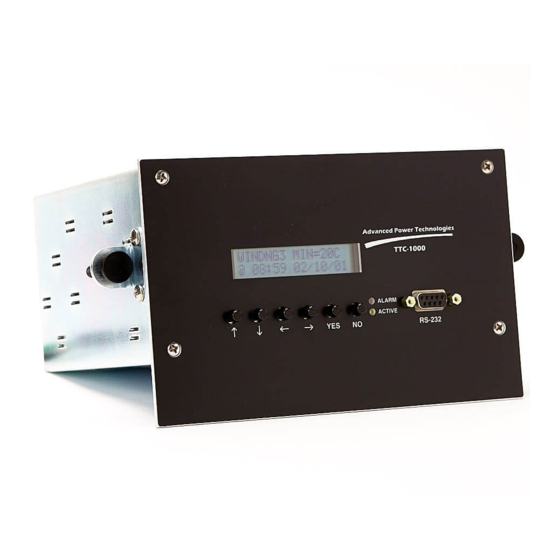
2.1 Controls & Indicators Figure 2.1 shows the front panel displays, indicators, and switches. Control layout of NEMA and panel units are identical other than panel size. Advanced Power Technologies TTC-1000 CLEAR WINDOW NO TEXTURE ALARM ACTIVE ... -
Page 15: Connection Overview- Panel Mount Unit
2.2 Connection Overview- Panel Mount Unit Analog Output Options Note : Not present if the analog output option is not selected Used for units with 4 Used for units with up to 3 isolated or non-isolated isolated or non-isolated analog outputs. TB5 is analog outputs. -
Page 16: Rear Layout- Panel Mount Unit
2.3 Rear Layout- Panel Mount Unit Analog Output Options Used for units with up to 3 isolated or non- isolated analog outputs. Used for units with 4 isolated or non- isolated analog outputs. TB7 & TB8 are optional digital inputs. These terminals will not be present if the additional input option is not selected . -
Page 17: Connections Overview - Nema Enclosure
2.4 Connections Overview - NEMA Enclosure Analog Daughter Card Options Note: Card not present if the analog output option is not selected For all isolated analog options, TB4 is For qty. 1-3 non-isolated a 9 position plug-in style block. For analog outputs, TB4 is a 6 the 4 (quad) non-isolated analog position plug-in style block. -
Page 18: Rear Panel Layout- Nema Enclosure
2.5 Rear Panel Layout- NEMA Enclosure Note: Card not present if the analog Analog Daughter Card Options output option is not selected For qty. 1-3 non-isolated analog outputs, TB4 is a 6 position plug-in style block. For all isolated analog options, TB4 is a 9 position plug-in style block. -
Page 19: Specifications
Specifications Power Supply Input Operating Range: 38 VDC to 290 VDC or 120 VAC +/- 10%, 3 Watts Max Operating Temperature Range: -50 °C to +85 °C, 95% Relative Humidity (non condensing) Liquid Temperature Measurement Range: -35 to +160 °C LTC Differential Temperature Measurement Range: -20 to +20 °C Winding Temperature Measurement Range:... - Page 20 Dimensions: Panel Mount: 7.20” W x 3.558” H x 6.0”D Aluminum NEMA 4X: 15.25” H x 7” W x 5.25” D. 304 Stainless Steel Surge Withstand/Fast Transient: Relay outputs, and station battery inputs: ANSI C37.90.1 EMI Withstand: ANSI C37.90.2 Electrostatic Discharge: IEC 801-2 Timers: Output and Load Pick Up Timer: 0 to 255 seconds (actual minimum delay 32...
-
Page 21: Part Number Details
2.7 Part Number Details Table 2.1: Ordering Options NOTE: Consult the factory for other options not listed. V6.230 20131017... -
Page 22: Installation And Connections
3 INSTALLATION and CONNECTIONS The following section gives information on hookup of power, temperature probes, split core CT, outputs, optically isolated inputs, analog outputs along with connections to RS232 and RS485 or fiber optics for DNP3.0 or MODBUS communications. There are two mounting configurations available. Panel Mounts are intended for installation inside the transformer control cabinet and NEMA 4X for mounting either inside or outside the control cabinet. -
Page 23: Power Hookup
38 to 160 VDC or from AC voltage of 120 ±10% VAC. Power is connected to terminals 1 and 2 on TB-3. The TTC-1000 is not sensitive to polarity because it uses a bridge rectifier on the power input. This feature eliminates the risk of damage due to the reversal of power applied to this input. -
Page 24: Temperature Probes
NEVER CONNECT POWER TO TERMINALS DESIGNATED FOR THE AUX CT. SERIOUS DAMAGE WILL OCCUR. Temperature Probes The TTC-1000 can be equipped with up to three probes. Universal thermowell probe types TTC-PROBE-01 and TTC-PROBE-11 are each provided with three thermometer well adapter fittings: 7/8-UNF (ANSI/IEEE C57 thermometer well), ½-NPT and ¾-NPT and three probe sleeves: 0.481, 0.625 and 0.675 OD. -
Page 25: Ttc-Probe-11 Installation
To install the probe into the thermo well: 1. Select the appropriate thermo well adapter fitting and either wrap the male threads with Teflon tape or coat with suitable pipe dope compound. Once the male threads are prepared, thread the adapter fittings into the thermo well. -
Page 26: Magnetic Mount Probe (Ttc-Probe-02) Installation
2. If the probe well’s ID is greater than 0.390 select the appropriate probe sleeve and slide over the probe. Tighten the set screw with the accompanying Allen Key. 3. Slide the probe into the thermo well. 4. Thread the appropriate brass fitting into the thermometer well. The spring holds the probe at the end of the well. -
Page 27: Probe Lead Connections
Figure 3.7: Magnetic Mount, Side View RTV Seal Tank Wall Figure 3.8: Magnetic Mount, Application of RTV 3.3.4 Probe Lead Connections The probe leads are color-coded and are inserted into the terminal block in the following sequence: Table 3.1: Probe Lead Connections Probe Panel Marking Wire Color... -
Page 28: Figure 3.9A: Nema Connections
The total wiring length can not exceed 250 feet. Also it is important to ensure that the cable’s shield drain wire is directly attached to the chassis of the TTC-1000 shown in Figure 3.10. Figure 3.10:... -
Page 29: Applying A Backup Temperature Probe
The TTC-1000 looks at the probe names to determine which probe to use for which function, such as TOP OIL. It looks at the channels starting at probe channel 1, then 2, then 3. -
Page 30: Figure 3.12A: Nema Ct Connections
RESULT IF THE SECONDARY LEADS OF THE BUSHING CT ARE CONNECTED DIRECTLY TO THE UNIT. 2. THE SHIELD DRAIN WIRE FROM THE SUPPLIED AUX CT MUST BE CONNECTED TO THE CHASSIS OF THE TTC-1000. SEE SECTION 3.10 FOR SHIELD DRAIN GROUNDING. V6.230 20131017... -
Page 31: Cooling Control And Condition Alarm Connections
3.5 Cooling Control and Condition Alarm Connections Figures 3.13 a&b illustrate the connections of the form C dry relay contacts for both NEMA and panel mount models. Figure 3.13b shows these connections on panel mount models and 3.13a for NEMA models, Each relay is capable of carrying 10 Amps at 230 VAC. -
Page 32: Unit Alarm Connections
The TTC-1000 monitors five conditions: Processor (DEVICE), Temperature (TPROBE), Winding (WNDG), Communications Processor (CPROC) and Manual Mode (MANUAL). The TTC-1000 allows the user to enable or disable any or all of the alarm conditions, except the Communications Processor alarm, through programming. -
Page 33: Telemetry Connections
No connection 3.7.2 Analog Outputs The TTC-1000 is available with up to four analog outputs configured as current loops. The source for each analog output can be selected from probe 1 (P1), probe 2 (P2), or calculated winding temperature. The analog output is designed to operate with a maximum series resistance of 10,000 Ohms when set to 0 to 1 mA or 510 Ohms when set to 4 to 20 mA. -
Page 34: Figure 3.15A: Tb5 Connections To Plug-In Analog Output Module
It is highly recommended that the shield drain should be grounded on the chassis of the TTC-1000. Not grounding the shield on the TTC-1000 end may either result in spurious analog values or possible damage to the analog outputs. -
Page 35: For Dnp3.0 Or Modbus Communications
Figure 3.16 Jumper location and connection Jumper J2 must be installed if the TTC-1000 is either the first or last device on the multi-drop communications bus. Installation of the jumper connects a 120 ohm termination resistor. Termination is vital to reduce reflections which affect proper operation when the length of the communications bus is long and/or there are many devices connected. -
Page 36: Fiber Optic Interface For Dnp3.0 Or Modbus Communications
In the event that the shield must be grounded on the opposite end of the TTC-1000, a 300 volt 0.47 µF capacitor should be added between the shield drain and the TTC-1000 chassis. Alternatively, a 300 volt 1.0 µF capacitor can be used for every two shield drain wires. -
Page 37: Figure 3.17: Outline Of Fiber Optic Interface
V-Pin Style Optical Budget Specifications: The optical budget for the TTC-1000’s V-Pin style optical interface is = 8.7dB HSC cable: 5.7dBm/12 (dB/km) = 470m => (10% margin) 400m approx. 1300 ft POF cable: 5.7dBm/0.23 (dB/m) = 24.8m => (10% margin) 22.3m approx. 73 ft The fiber optic interface has the ability to operate either point to point or can be daisy chained with other intelligent electronic devices. -
Page 38: Setting Repeat Mode On Fiber Optic Channel
3.7.5 Setting Repeat Mode on Fiber Optic Channel On units equipped with a fiber optic communications channel you can configure the fiber interface for repeat mode. This passes incoming data to the transmit channel transparently. To change this setting, access the CONFIGURATION PROGRAM menu from the front panel as discussed in Section 4.1. -
Page 39: Optically Isolated Inputs
3.8 Optically Isolated Inputs Models equipped with inputs contain up to two optically isolated inputs, IN1 and IN2. These inputs must be wetted from an external power supply between 38 and 160 VDC or 38 to 120VAC. Connections are made through plug-in terminal blocks on the rear of the case as shown in figures 3.18a &... -
Page 40: Heater Connections
NEMA 4 enclosure on the TTC-1000. Failure to ground the shield drain wire on the TTC-1000 end may cause reading errors and possible unit damage. - Page 41 THIS PAGE INTENTIONALLY LEFT BLANK V6.230 20131017...
-
Page 42: Settings
Proper operation of the TTC-1000 has been verified with Windows Terminal and HyperTerminal. For settings through a PC you will need a female to male DB-9 null modem cable. The TTC-1000 is fixed to communicate at 9600 bits/sec with 8 bits, no parity and one stop bit. -
Page 43: Programming Settings Through A Pc
UP or DOWN arrow button. 4.2 Programming Settings Through a PC Data communications from the TTC-1000 is implemented through the front panel mounted DB-9 connector at a fixed data rate of 9600 bits per second, 8 bits of data, no parity, and one stop bit. - Page 44 PROGRAM SETPOINT AND LOGIC SETTINGS 01 SP11 PCKUP=00 øC 02 SP11 DROUT=00 øC 03 SP12 PCKUP=00 øC 04 SP12 DROUT=00 øC 05 SP13 PCKUP=00 øC 06 SP13 DROUT=00 øC 07 SP14 PCKUP=00 øC 08 SP14 DROUT=00 øC 09 SP21 PCKUP=00 øC 10 SP21 DROUT=00 øC 11 SP22 PCKUP=00 øC 12 SP22 DROUT=00 øC...
- Page 45 71 LSP41 PCKUP=00.0 A 72 LSP41 DROUT=00.0 A 73 LSP42 PCKUP=00.0 A 74 LSP42 DROUT=00.0 A 75 LSP51 PCKUP=00.0 A 76 LSP51 DROUT=00.0 A 77 LSP52 PCKUP=00.0 A 78 LSP52 DROUT=00.0 A 79 LSP61 PCKUP=00.0 A 80 LSP61 DROUT=00.0 A 81 LSP62 PCKUP=00.0 A 82 LSP62 DROUT=00.0 A 83 LSP71 PCKUP=00.0 A...
- Page 46 142 LSP12 Not Assigned 143 LSP21 Not Assigned 144 LSP22 Not Assigned 145 LSP31 Not Assigned 146 LSP32 Not Assigned 147 LSP41 Not Assigned 148 LSP42 Not Assigned 149 LSP51 Not Assigned 150 LSP52 Not Assigned 151 LSP61 Not Assigned 152 LSP62 Not Assigned 153 LSP71 Not Assigned 154 LSP72 Not Assigned...
- Page 47 31 OUT7=Not INVERT (0) 32 OUT8=Not INVERT (0) 33 CT RATIO1=00 34 RATED LOAD1=00 A 35 WINDING RISE1 @ RATED LOAD=00 øC 36 CT RATIO2=00 37 RATED LOAD2=00 A 38 WINDING RISE2 @ RATED LOAD=00 øC 39 CT RATIO3=00 40 RATED LOAD3=00 A 41 WINDING RISE3 @ RATED LOAD=00 øC 42 WINDING TC=00 MIN 43 COOLING TYPE=Not DIRECTED FOA (0)
- Page 48 On the “Enter Code:” line type “11” and press “Enter” to access the submenu for digital inputs and Tap Position Monitoring. Another submenu listing should appear with “Enter Code:” prompt waiting for your input. At the prompt type “2/” followed by the four password digits to access the digital inputs and tap position monitoring program menu followed by “Enter”.
- Page 49 59 RESET CONTACT INPUT = NONE (0) 60 OFFTAP CONTACT TYPE = NO (0) 61 RAISE CONTACT TYPE = NO (0) 62 LOWER CONTACT TYPE = NO (0) 63 UPPER LIMIT CONTACT TYPE = NO (0) 64 LOWER LIMIT CONTACT TYPE = NO (0) 65 RESET CONTACT TYPE = NO (0) 66 TAP 26R INFO=00 67 TAP 25R INFO=00...
-
Page 50: Firmware Version From The Front Panel
entered, “Enter Code:” will be displayed until Enter is pressed without data. To start the scrolling again, simply type “+” followed by Enter. 4.3 Firmware Version from the Front Panel The firmware version can be obtained from the front panel by pressing ... - Page 51 5 to 10 minutes. The TTC-1000 also equipped with a feature to run the winding temperature calculation from a redundant top oil probe should the primary top oil probe fail.
-
Page 52: Ct Ratio
4.4.1 CT RATIO The CT RATIO is the CT ratio of the bushing CT which the split core CT is applied to. The CT ratio must be relative to 1. Therefore, if the CT ratio is 300:5 the CT ratio to enter is 60. The ratio of the split core is already accommodated in the unit. -
Page 53: Hot Spot Rise Over Top Oil
Enter:34/1473 This will program the Rated Load to 1473 Amps. 4.4.3 Hot Spot Rise over Top Oil The Hot Spot Rise over Top Oil setting is either a number that can be obtained from the transformer manufacturer, deduced from heat run data or estimated in the range of 18 to 22 º... -
Page 54: Calculated Winding Exponent Setting
digits. The currently active digit will flash. Press YES after you have entered all digits. For programming from a PC just type the Winding TC on the “Enter:” line as follows: Enter:42/7 This will program the winding rise time constant to 7 minutes. 4.4.5 Calculated Winding Exponent Setting The m exponent used to calculate winding temperature can be modified. - Page 55 Press the arrow button until the display reads: VIEW WNDGCAL PRESS YES TO VIEW Press YES so the display reads: WNDG TEMP AT 5A WINDINGCAL = 45°c Read the number where 45 appears above, record this number. This is the computed value of the current top oil plus the rated rise of the transformer at 5 amperes of CT current.
-
Page 56: Probe Names
4.5 Probe Names 4.5.1 Setting Probe Names After connecting the probe or probes and verifying that they are measuring temperature, you can choose one of the following names for each probe in Table 4.2. Table 4.2: Probe Names Top Oil Top Oil 2 Winding 3 Selector Tank... -
Page 57: Setting Winding Names
Press the YES button. The first character will flash. Use the arrow buttons to scroll through the available names. Press YES after you have made your selection. When programming from a PC the following are the valid codes for the probe names available are shown in the table above. -
Page 58: Setting Load Names
Therefore to display WINDING for Winding 1 type: Enter:47/1 In a similar manner, the remaining winding names would be on program lines 48 and 49. 4.5.3 Setting Load Names Loads can be selected from Table 4.4. Table 4.4: Load Names LOAD BANK2A 14 PUMPC... -
Page 59: Temperature Set Points
4.6 Temperature Set Points The TTC-1000 has four independent temperature set points per temperature probe and each probe has four calculated winding set points associated with it if used with a CT and the options for winding temperature calculation are set. Each set point has its own pick up and drop out temperatures. -
Page 60: Figure 4.2: Under Temp Operation
Temperature Figure 4.2: Under Temp Operation SPpn Drop Out Temperature SPpn Pick Temperature Time SPpn Once a set point has picked up, it will not drop out until the pre-programmed conditions are met. This feature is especially useful to allow the fans to continue to run until the top oil temperature drops to some lower temperature. -
Page 61: Setting Liquid Pickup And Drop Out Temperatures
3. Similarly SP31, SP32, SP33, and SP34 do not have any function in dual probe units. 4. WSP21, WSP22, WSP23, WSP24 drop out and pick up are settable in models without the calculated winding feature (no AUX CT), but do not have any function. -
Page 62: Setting Calculated Winding Pickup And Dropout Temperatures
Press the YES button. The first digit will flash. Use the arrow buttons to scroll through the digits. Use the buttons to scroll between the digits. The currently active digit will flash. The first digit will scroll ‘-‘, 0, 1. The second digit will scroll 0 to 9 if the first digit is 0, 0 to 6 if the first digit is 1 and last digit is 0, 0 to 5 if the first digit is 1 and the last digit is greater than 0. -
Page 63: Load Pickup Set Points
PRGM SETTING 025 WSP11 PCKUP= 7 5C Press the YES button. The first digit will flash. Use the arrow buttons to scroll through the digits. Use the buttons to scroll between the digits. The currently active digit will flash. The first digit will scroll ‘-‘, 0, 1. The second digit will scroll 0 to 9 if the first digit is 0, 0 to 6 if the first digit is 1 and last digit is 0, 0 to 5 if the first digit is 1 and the last digit is greater than 0. -
Page 64: Figure 4.3: Load Pickup Set Point Operation
Each load set point has its own pickup and drop out current setting. Each setting is adjustable from 0 to 9.9 Amps in 0.1 Amp increments for the CT channel on the Main Board and 0 to 50.0 Amps in 0.1 Amp increments on the CT board. These settings are based on the primary current measured by the split core CT. -
Page 65: Setting Load Pickup Set Point
temperature, the set point operates as an under load detector. Conversely, setting the pickup point higher than the dropout point allows the set point to operate as an overload detector. Setting one set point for under load and the other as overload permits detection of the cooling system’s load current “sweet spot”. -
Page 66: Setting Load Pickup Timer
This will program the Load pickup timer to 120 seconds. 4.8 Optically Isolated Input Settings The TTC-1000 may be optionally equipped with up to 14 optically isolated inputs. Each input contains a limiting resistor that allows these inputs to recognize a wide range of input voltage of 38 to 160 Volts AC or DC as being picked up. -
Page 67: Figure 4.4: Input Set For Level
Each of the digital inputs can be set either as level active, LEVEL MODE or PULSE MODE (positive or negative edge, depending on the INVERSION setting for that particular input). For LEVEL MODE, the recognized state of IN1 or IN2 follows the voltage applied to the input. - Page 68 Programming from the front panel’s TPM PRGM menu press the arrow button until the setting for desired input is displayed, IN1 starts at setting 001: PRGM SETTING 001 I N 1 C N T R L = L E V E L ...
-
Page 69: Programmable Logic Settings
SP11 will cause SP11 to be recognized as true whenever it is de-asserted. Also, these specific operands can be either AND’ed () or OR’ed (+) to a specific output. In evaluating a specific output, the TTC-1000 groups all of the OR’ed terms together and all of the AND’ed terms together. -
Page 70: Assigning Liquid Temperature Set Points
This is particularly useful for fail safe operation. NOTE: Fail safe operation is strongly recommended. Fail safe operation ensures that the cooling system picks up whenever the TTC-1000 becomes de-energized or encounters a failure. Fail safe requires the output relay controlling the cooling stage to drop out instead of picking up. - Page 71 NOTE: Do not assign set points for probes if they are being used for LTCDIFF functions. To assign a liquid set point (SP11, SP12, SP13, SP14, SP21, SP22, SP23, SP24, SP31, SP32, SP33, or SP34) to an output from the front panel, go into the MAIN Program menu and do the following.
-
Page 72: Assigning Winding Temperature Set Points
The remaining set points, SP12, SP13, SP14, SP21, SP22, SP23, SP24, SP31, SP32, SP33, and SP34 can be assigned by pressing the arrow button and following the above procedure. For programming from a PC just type the SP11 assignment on the “Enter:” line as follows: Enter:113/0/1/1... -
Page 73: Assigning Load Pickup Set Points
Use the buttons to scroll to the output #. The output number will flash. Use the arrow buttons to scroll from 0 to 8. Setting the output number to zero will have the effect of de-assigning the set point. The following illustrates the change to output 1: PRGM SETTING 129 WSP11 + TO OUT1... -
Page 74: Assigning In1 Through In14
PRGM SETTING 141 ! LSP11 TO OUT0 Use the buttons to scroll to the AND/OR logic operator. The operator will flash. Use the arrow buttons to scroll between the and + operators. Selecting will AND LSP11 with any other set point or operand controlling the ... - Page 75 stage of cooling through a switch on the control panel or even from your RTU. It can also be used to block an output relay should the need arise. One such application could be the blocking of a high temperature trip. To assign the IN1 to ...
-
Page 76: Assigning Outputs
For programming from a PC just type the IN1 assignment on the “Enter:” line as follows: Enter:29/0/1/1 This will assign IN1 OR’ed to OUT1. To assign !IN1 And’ed OUT1: Enter:29/1/0/1 Consult the setting sheets to assign IN2 through IN14. 4.9.5 Assigning Outputs The OUT1, OUT2, OUT3, OUT4, OUT5, OUT6, OUT7, &... -
Page 77: Time Set Points
PRGM SETTING 159 OUT1 + TO OUT0 Use the buttons to scroll to the output #. The output number will flash. Use the arrow buttons to scroll from 0 to 4. Setting the output number to zero will have the affect of de-assigning the set point. -
Page 78: Time Set Point Settings
A counter is provided to set the frequency at which the time set points will operate. For example, setting the counter to 7 will operate the time set points every 7 day. Time set points use a 24 hour clock. When using time set points in conjunction with temperature set points for the purpose of picking up a cooling bank in fail-safe mode, both set points should be assigned as usual. -
Page 79: Time Set Point Counter Settings
This will assign TIME1 OR’ed to OUT2. Consult the setting sheets to assign TIME2 and TIME3. NOTE: 1. ALL 4 DIGITS OF THE TIME SET POINT PICKUP AND DROP OUT TIMES MUST BE ENTERED TO SET THE CORRECT TIME. 2. IF USING ALTERNATE, THE STOP TIME OF THE FIRST SET POINT MUST OVERLAP THE START TIME OF THE SECOND SET POINT. -
Page 80: Setting Output Invert
This is particularly useful for fail safe operation of the controller. Fail safe operation is highly recommended as it allows your cooling system to be activated should the TTC-1000 become de-energized or a device or temperature probe alarm is detected. Fail safe operation is achieved by ensuring the output relay drops out when the necessary set points are satisfied to command a stage of cooling. -
Page 81: Application Examples
INVERT OUT2 through INVERT OUT8 can be selected by pressing the arrow button and following the above procedure. For programming from a PC just type the setting for output invert on the “Enter:” line as follows: Enter:25/1 This will set OUT1 to INVERT. Type 0 for OUT1 not INVERT. Consult the setting sheets to change INVERT OUT2 through INVERT OUT8. -
Page 82: Commanding The Cooling Fans
4.9.9.1 Commanding the cooling fans: The simplest application is using an output to control a cooling bank. First, program the Pickup and Dropout temperature set point. Second, assign the set point to an output as follows: OUT Using the LCD: where kl= 11,12,13,14,21,22,23,24,31,32,33,34 (Set point to be assigned) and n=1,2,3,4,5,6,7,8 (Output to be assigned to) Using RS232:... -
Page 83: Periodic Exercise Of Cooling Fans
Using the LCD: + OUT where k =,12,13,14,21,22,23,24,31,32,33,34 and n=1,2,3,4,5,6,7,8 + OUT where k =,12,13,14,21,22,23,24,31,32,33,34 and n=1,2,3,4,5,6,7,8 Using RS232: /0/1/n where kk =Parameter # and n=1,2,3,4,5,6,7,8 /0/1/n where kk =Parameter # and n=1,2,3,4,5,6,7,8 Use the INVERT OUTn setting to cause the output relay to drop out when either temperature set point is achieved. -
Page 84: Setting Output Control With Alarm
The TTC-1000 allows you to program how an output will react whenever there is a DEVICE or TPROBE alarm. There are four (4) ways an output can react whenever there is a DEVICE or TPROBE alarm: 1. - Page 85 3. Supervised (SUPVS): the output drops out when alarm occurs. 4. No action (NOACT): the output logic is not processed at all. The TTC-1000 output control default is UNCHG for each output. The user should decide how they wish each output to operate whenever there is either a DEVICE or TPROBE alarm.
-
Page 86: Alternate Fan Banks
Consult the setting sheets to change output control for OUT2, OUT3, OUT4, OUT5, OUT6, OUT7, and OUT8. 4.11 Alternate Fan Banks The TTC-1000 can be programmed to alternate the energization between two outputs. This feature is particularly useful when it is desirable to insure a fan bank is regularly exercised. -
Page 87: Auto And Manual Control
RS-232 interface. The TTC-1000 will cause the Device Alarm contacts to pick up when an output is put into the manual mode. In addition the ALARM LED on the front panel will illuminate. -
Page 88: Setting Control Of Unit Alarm
The TTC-1000 monitors five conditions: Processor (DEVICE), Temperature (TPROBE), Manual Mode (MANUAL), Winding (WNDCKT), DNP3.0 or MODBUS Communications (CPROC). The TTC-1000 allows the user to enable or disable all of the alarm conditions, except the DNP3.0 or MODBUS Communications (CPROC), through programming. -
Page 89: Temperature Probe Alarm Setting
PRGM SETTING 091 DEVICEALRM=DSABL Press YES when you have made the correct selection. Selecting DSABL will block the device alarm relay and the front panel alarm LED from illuminating. However, the front panel will display the device alarm if present. For programming from a PC just type the setting for device alarm enable on the “Enter:”... -
Page 90: Manual Mode Alarm Setting
CT current is less than 0.37 Amps. Note that the TTC-1000 has a zero threshold on the CT inputs of 0.37 Amps. Thus any secondary bushing current below this value will be interpreted by the TTC-1000 as 0.0 Amps. -
Page 91: Setting Date And Time
4.14 Setting Date and Time The TTC-1000 utilizes a real time clock to maintain date and time. This device has two functions. It supplies precise 32 millisecond time ticks for the Real Time Interrupt and it keeps track of the time, date and day of the week. Also, the time, date, and day are maintained even while the unit is unpowered for 5 days at 85ºC. -
Page 92: Setting Time And Date Via The Pc
flashes. Use the arrow buttons to set this digit. Press the YES button after entering the time. Setting the date from the front panel, enter the Configuration menu and press the arrow button until the setting 089 is displayed: PRGM SETTING 089 DATE=01/04/08 ... -
Page 93: Setting Unit Id
Programming from the front panel, enter the Configuration menu and press the arrow buttons until the setting 096 is displayed: PRGM SETTING 096 PASSWORD=0000 Press the YES button. The first digit will flash. Use the arrow buttons to ... -
Page 94: Tap Changer Position Monitoring (Tpm)
TTC-1000. 5.1.1 Minimal Configuration If the TTC-1000 has only the basic two contact sensing inputs installed, only the most basic form of monitoring can be implemented. This uses EITHER the Raise or Lower contactors and the Off-Tap Switch. -
Page 95: Full Configuration
Where the 84R & L relay coils are used, the wires must be landed directly across the 84R or 84L coil to the digital input of the TTC-1000 as many tap changer control circuits will have voltage from either side of the coil to Neutral when the other coil is operated. -
Page 96: Programming Items
NO or NC. 5.2.2 Start Position This is set for the position the tap changer is actually in when the TTC-1000 is connected and put into operation. It is the starting point the TTC-1000 will start tracking from. -
Page 97: Tlim
5.2.4 TLIM Set point that is picked up when the tap changer attempts to move beyond its limits. This setting selects the Output to be used to send the indication. 5.2.5 OFFTAP Timeout Set in seconds for the maximum time to be allowed for a tap change operation. Should this be exceeded, the OFFT set point will pick up. -
Page 98: Offtap, Raise And Lower Inputs
LOWER. 5.2.13 Upper Limit Input Number of the input connected to the Upper Limit Switch in the mechanism. This resets the count in the TTC-1000 to the programmed upper limit, should the limit switch close. 5.2.14 Lower Limit Input Number of the input connected to the Lower Limit Switch in the mechanism. This resets the count in the TTC-1000 to the programmed lower limit, should the limit switch close. -
Page 99: Tap Info
THRU taps, the values in this table of settings define what the TTC-1000 will report via DNP or MODBUS for each particular tap. Each possible tap in the TTC-1000 (+26 to -26) must be set for what it actually represents in the particular mechanism. -
Page 100: Configuring Tpm Settings Through Rs232 On Pc
WORKSHEET that has a complete listing of all the settings in this menu. 5.4.1 Tap Changer Position Monitoring Status and Statistics TPM functionality of TTC-1000 also includes the ability to collect statistical information about the tap changes. To access this status screen type “3” followed by “Enter”... -
Page 101: Tap Changer Position Monitoring Targets
Targets are the alarms that stay picked-up once they pick-up. The only way to clear them is to reset them either from Front Panel or through RS232. All targets will reset together. TTC-1000 has 6 targets implemented: LTCDIFF1 RofR, LTCDIFF2 RofR, TLIM, OFFT, OPFL, and FREQ. -
Page 102: Dual Algorithm Ltc Condition Monitoring
6 Dual Algorithm LTC Condition Monitoring The TTC-1000 has several set points that the user can employ for LTC conditioning monitoring. The LTC differential is the mathematical difference between the probe named LTCDIFF, LTCDIFF1, LTCDIFF2, LTCTANK, SELTANK or DIVTANK and top oil temperature. Therefore is only available in units with more than one temperature probe. -
Page 103: Detection Of Slowly Evolving Problems
LTC Set Point Figure 6.1: LTC Differential Set Point Operation The TTC-1000 uses an LTC pickup timer settable from zero to 999 minutes to supervise the LTC set point. The above example shows that the differential set points do not pickup until after the timer is complete. If the differential temperature drops down below the pick up temperature while the timer is in progress, the timer will reset. - Page 104 NOTE: The LTCDIFF and LTCDIFF1 & 2 temperature displayed is the ±20°C calculated differential up to a maximum of . The corresponding analog output tracks this differential temperature only if the probe or probes used are named LTCDIFF or LTCDIFF1 or LTCDIFF2. All LTCDIFF temperature set points are designed to read negative as well as positive because sometimes the LTC tank runs cooler than the top oil temperature.
-
Page 105: Setting Ltcdiff Set Point
NOTE: In single probe versions, all LTCDIFF pickup and dropout settings display “N/A”. Be careful to check that the LTCDIFF & LTCDIFF1 & 2 pickup and dropout set points are never set to greater than 20 or less than –20. Erroneous operation of the LTCDIFF pickup or dropout will result if these set points are set beyond the stated range. -
Page 106: Setting Ltcdiff Pickup Timer
6.1.2 Setting LTCDIFF Pickup Timer Programming LTCDIFF1 and LTCDIFF2 pick up timers from the front panel, press the arrow buttons until the setting 053 is displayed: PRGM SETTING 053 LTCPUTMR1=480MIN Press the YES button. The first digit will flash. Use the arrow buttons to ... - Page 107 Selecting will AND LTC with any other set point or operand controlling the same output. PRGM SETTING 125 LTC1 TO OUT0 to permit or block an output from operating. Selecting + will OR LTC with any other set point or operand controlling the same output. Use + when you have a number of operands which can command the same output: ...
-
Page 108: Detection Of Quickly Evolving Problems
6.2 Detection of Quickly Evolving Problems Figure 6.2 illustrates the LTCDIFF rate of rise method. Temperature LTCDIFF RISE Time LTCDIFF RATE LTCDIFF LTCDIFF RofR Figure 6.2: LTCDIFF Rate of Rise Method The LTCDIFF Rate of Rise method uses two parameters: LTCDIFF RISE and LTCDIFF RATE. -
Page 109: Setting Ltcdiff Rise
6.2.1 Setting LTCDIFF Rise Programming LTCDIFF Rise from the front panel, enter the Set point menu and press the arrow buttons until the setting 055 is displayed: PRGM SETTING 055 LTCDIFFRISE=15 C Press the YES button. The first digit will flash. Use the arrow buttons to ... -
Page 110: Telemetry Options
7.1 Analog Outputs The TTC-1000 is available with up to three analog outputs configured as current loops. The source for each analog output can be selected from probe 1 (P1), probe 2 (P2), probe 3 (P3), or calculated winding temperature. The analog output is designed to operate with a series resistance of 10,000 Ohms when set to 0 to 1 mA or 510 Ohms when set to 4 to 20 mA. - Page 111 Probe Min @ -35 Min @ 0 0 to 1 mA Range: P1, P2, or P3 0 mA @ -35 ºC 0 mA @ 0 ºC 1 mA @ 160 ºC CALC. WINDING 0 mA @ -35 ºC 0 mA @ 0 ºC 1 mA @ 180 ºC LTCDIFF1 &...
-
Page 112: Table 7.1: Tap Position Analog Ranges
P1, P2 or P3 For measurements from :Current = 0.08205 x Temperature +6.872 For calculated winding temperature: Current = 0.07442 x Temperature + 6.605 For LTCDIFF the relationship is as follows: Range 0 to 1mA: Current Temperatur Range 4 to 20mA:... -
Page 113: Setting The Analog Output Range
1.00000 20.000 NOTE: If any analog channel is set to report current tap changer position (TPM feature), TTC-1000 will automatically switch to enable negative scaling on all analog channels to accommodate for better resolution. 7.1.1 Setting the Analog Output Range The analog output range can be switched from 0 –... -
Page 114: Setting The Analog Source
7.1.2 Setting the Analog Source The source of data for the analog input can be a liquid probe or calculated winding temperature. The TTC-1000 automatically scales the data to be reported. To change this setting, enter PROGRAM mode from the front panel as discussed in Section 4.1. -
Page 115: Enabling Negative Scaling
Press YES when you have made the correct selection. A2, A3, & A4 sources can be selected by pressing the arrow button and following the above procedure. For programming from a PC, enter PROGRAM through the main menu as discussed in Section 0. - Page 116 8 data bits, 1 stop bit, and no parity. The TTC-1000 implements DNP3.0 Level 1 communications. This includes Class 0 polls (Object 60 Variation 1) of analog and binary output points. The TTC-1000 supports Object 1 Variation 2 binary outputs. Binary outputs include all temperature and load set points along with the state of each output relay.
-
Page 117: Setting Baud Rate
“local forced” bit in the appropriate Binary Output point, as noted above, before attempting to exert control as the TTC-1000 will remember that the bit has been exerted even though the TTC-1000 is in Manual Mode. Once an output is released from Manual Mode, the output will either return to automatic or remote control. -
Page 118: Setting Node Address
Configuration menu and press the arrow button until the setting 067 displayed: PRGM SETTING 067 BAUD RATE= 1200 Press the YES button. The first character will flash. Use the arrow buttons to scroll between 1200, 2400, 9600 and 19200. PRGM SETTING 067 BAUD RATE= 9600 Press YES when you have made the correct selection. -
Page 119: Setting Remote Blocking
9 pin female to 9 pin male null modem cable. The TTC-1000 permits remote reporting of temperature or resetting of the time of day by sending a forward slash ‘/’ followed by either the characters T... - Page 120 68/93 Where the first temperature is probe #1 and the second is probe #2. Sending the string /S causes the TTC-1000 to report the status of the output relays (OUT1, OUT2, OUT3 OUT4, OUT5, OUT6, OUT7, and OUT8) and alarm type (DEVICE, TPROBE, and WDGCKT) as a series of ASCII character ‘0’...
- Page 121 PAGE INTENTIONALLY BLANK V6.230 20131017...
-
Page 122: View Temperatures
8 VIEW TEMPERATURES 8.1 View Scrolling Display The temperature & time display will be the first display you see upon power up. Date, time, and temperature are updated when fresh data is available. The display will continuously scroll through a set sequence. The sequence will depend on the number of liquid temperature probe channels and if the unit is equipped to measure calculated winding temperature. -
Page 123: Table 8.1: Display Scroll Sequence
Table 8.1: Display Scroll Sequence Item Scroll Item Requirements Probe 1 Standard Probe 2 Option Probe channel Probe 3 Option Probe channel Winding 1 Temp Option CT channel, winding data Winding 1 Load Winding 2 Temp Option CT channel, winding data Winding 2 Load Winding 3 Temp Option... -
Page 124: Reset Ltcdiff Rate Of Rise
8.3 Reset LTCDIFF Rate of Rise To reset the Rate of Rise after it has been picked up from the front panel main menu, press the arrow buttons until the following menu item is displayed and press the YES button: RST RATE OF RISE PRESS YES TO RST To confirm that the Rate of Rise element has been reset, the display will read:... - Page 125 To confirm that the overall TPM Counter has been reset, the display will read: OVERALL TPM CNTR IS RESET V6.230 20131017...
-
Page 126: View Settings
9 View Settings View allows display of settings without entering PROGRAM. Settings may be viewed from the front panel or via a PC. 9.1 View Settings Via Front Panel To view Set point settings from the front panel, first press the arrow buttons until the VIEW Settings screen is displayed: VIEW SP STTINGS... -
Page 127: View Settings Via Pc
9.2 View Settings Via PC To view Set point settings via a PC, first press the Enter key to display the Main Menu. When the user presses 1 followed by the Enter key, the user will see the following display: VIEW SETPOINT AND LOGIC SETTINGS 01 SP11 PCKUP=00 øC 02 SP11 DROUT=00 øC... - Page 128 63 LSP21 PCKUP=00.0 A 64 LSP21 DROUT=00.0 A 65 LSP22 PCKUP=00.0 A 66 LSP22 DROUT=00.0 A 67 LSP31 PCKUP=00.0 A 68 LSP31 DROUT=00.0 A 69 LSP32 PCKUP=00.0 A 70 LSP32 DROUT=00.0 A 71 LSP41 PCKUP=00.0 A 72 LSP41 DROUT=00.0 A 73 LSP42 PCKUP=00.0 A 74 LSP42 DROUT=00.0 A 75 LSP51 PCKUP=00.0 A...
- Page 129 168 TIME2 00:00 TO 00:00 Not Assigned 169 TIME3 00:00 TO 00:00 Not Assigned After transmitting the data to the host computer, the TTC-1000 automatically logs off. The user must press the Enter key to re-display the Main Menu. To view Configuration settings via a PC, first press the Enter key to display the Main Menu.
- Page 130 23 OUT8 AUTO (0) 24 OUT8 UNCHG (0) w/ALRM 25 OUT1=Not INVERT (0) 26 OUT2=Not INVERT (0) 27 OUT3=Not INVERT (0) 28 OUT4=Not INVERT (0) 29 OUT5=Not INVERT (0) 30 OUT6=Not INVERT (0) 31 OUT7=Not INVERT (0) 32 OUT8=Not INVERT (0) 33 CT RATIO1=00 34 RATED LOAD1=00 A 35 WINDING RISE1 @ RATED LOAD=00 øC...
- Page 131 94 TIME SP CNTR=00 95 UNIT ID= After transmitting the data to the host computer, the TTC-1000 automatically logs off. The user must press the Enter key to re-display the Main Menu. To view Tap Position Monitoring settings via a PC, first press the Enter key to display the Main Menu.
- Page 132 57 UPPER LIMIT CONTACT INPUT = NONE (0) 58 LOWER LIMIT CONTACT INPUT = NONE (0) 59 RESET CONTACT INPUT = NONE (0) 60 OFFTAP CONTACT TYPE = NO (0) 61 RAISE CONTACT TYPE = NO (0) 62 LOWER CONTACT TYPE = NO (0) 63 UPPER LIMIT CONTACT TYPE = NO (0) 64 LOWER LIMIT CONTACT TYPE = NO (0) 65 RESET CONTACT TYPE = NO (0)
- Page 133 PAGE INTENTIONALLY BLANK V6.230 20131017...
-
Page 134: Status
10 STATUS STATUS allows you to take a snapshot of the recognized state of any output, temperature set points, LOAD, LTCDIFF set points, time set points and optically isolated inputs. In the case of outputs, this will be the state of the programmable logic. - Page 135 WSP11=PICKED UP WSP12=PICKED UP WSP13=PICKED UP WSP14=PICKED UP WSP21=PICKED UP WSP22=PICKED UP WSP23=PICKED UP WSP24=PICKED UP WSP31=PICKED UP WSP32=PICKED UP WSP33=PICKED UP WSP34=PICKED UP LSP11=PICKED UP LSP12=PICKED UP LSP21=PICKED UP LSP22=PICKED UP LSP31=PICKED UP LSP32=PICKED UP LSP41=PICKED UP LSP42=PICKED UP LSP51=PICKED UP LSP52=PICKED UP LSP61=PICKED UP...
-
Page 136: Setting Files
PC use Upload Setting file. To transfer a previously stored setting file from your PC to the TTC-1000, use Download Setting file, or you can use the “Send CSV Settings To Unit” menu option to send a comma separated variable settings file. -
Page 137: Upload Settings Using Hyperaccess
If the number of retries exceeds 3, cancel and start over. At this point the transfer will not take place. Recheck your settings. d. If the main TTC-1000 menu returns to the HyperTerminal window, the transfer has timed out and the procedure must be restarted. -
Page 138: Download Setting Files
TTC-1000 is ready to accept the settings file. SETTING FILE TRANSFER IN PROGRESS. PRESS Any KEY TO ABORT”. §§§§§§§§§§§§§§ 4. To send the file to the TTC-1000, click on Transfer on the HyperTerminal toolbar a. A drop down menu will appear b. -
Page 139: Download Settings Using Hyperaccess
TTC-1000 is ready to accept the settings file. SETTING FILE TRANSFER IN PROGRESS. PRESS Any KEY TO ABORT”. §§§§§§§§§§§§§§ 4. To send the file to the TTC-1000, click on Transfer on the HyperAccess toolbar a. A drop down menu will appear b. -
Page 140: Download Settings Using A *.Csv Template With Hyperaccess
The dialog box will disappear and a note will appear in the terminal window that the transfer was successful. NOTE: The TTC-1000 has the ability to detect if a wrong setting file after the file is received. A message “WRONG FILE” will appear if the setting file is incorrect for the firmware version of the TTC-1000. - Page 141 CSV FILE TRANSFER IN PROGRESS. PRESS Any KEY TO ABORT”. §§§§§§§§§§§§§§ 4. To send the file to the TTC-1000, click on Transfer on the HyperAccess toolbar a. A drop down menu will appear b. Click on the Send File option 5.
-
Page 142: Data Logging
12 DATA LOGGING Data logging permits storage of time stamped temperature and load data. The user has the ability to change the time base used for time stamping from 1 to 9999 seconds. Setting the time base to zero erases the log and prevents records from being recorded. -
Page 143: Data Points
After selecting the data points to log, it is simple to figure out the length of time data can be recorded. For example if 30 minutes time stamping is required, Time Base=1800, and P1, P2, Winding & Load are required (3 temps & 1 load), the maximum time that data can be recorded in days is equal to 9,289 divided by 48 records per day or 193 days. -
Page 144: Selecting Data Points
For programming from a PC, enter PROGRAM through the main menu as discussed in Section 4.2. Once in PROGRAM, type the setting for the time base on the “Enter:” line as follows: Enter:71/3600 This will set the Time Base to 3600 seconds. 12.4 Selecting Data Points Any or all of the data points can be selected for logging. -
Page 145: Add Or Delete P3 From Log
Press the YES button. The first character will flash. Use the arrow buttons to scroll between YES and NO. For programming from a PC, enter PROGRAM through the main menu as discussed in Section 0. Once in PROGRAM, type the setting for P2 RECORD on the “Enter:”... -
Page 146: Add Or Delete Load1 From Log
For programming from a PC, enter PROGRAM through the main menu as discussed in Section 0. Once in PROGRAM, type the setting for Calculated Winding Record on the “Enter:” line as follows: Enter:75/1 This will add Calculated Winding to the log. Type 0 to remove from the log. 12.4.5 Add or Delete Load1 From Log To change this setting, enter PROGRAM mode from the front panel as discussed in Section 4.1 To set the LOAD1 RECORD from the front panel, enter the... -
Page 147: Viewing The Data Log
To view the log via a PC, open the terminal emulation program with the settings used to access the main TTC-1000 menu. First press the Enter key to display the Main Menu: Advanced Power Technologies, LLC; (C) 2004-2008 Transformer Temperature Controller V6.23... -
Page 148: Import Data Log Using Hyperterminal
The first line is the header for the data reported. The last character is a carriage return (CR) character, hex 013, and line feed (LF), hex 011. Each subsequent line is the comma delimited data followed by a CR and LF characters. 12.6 Import Data Log Using HyperTerminal To capture the text using HyperTerminal, do the following: 1. -
Page 149: Import To Excel
9. Select Stop from the next menu, the file is now saved and closed. 12.7 Import to Excel The text file captured can be imported into excel for plotting and sorting. It is a good idea to open the text file in Notepad to delete any extra characters before trying to import the file into excel. - Page 150 2. Go to the Path where the text file is stored and select Files of Type: Text Files, Double Click the file name and Click Open: 3. Click the Delimited button and click Next: V6.230 20131017...
- Page 151 4. Check the Comma box in Delimiters. Make sure all other boxes are unchecked: 5. Click the General button in the Column data format and click Finish: V6.230 20131017...
- Page 152 6. After closing the import wizard, the text data will display: The data is now ready for graphing. V6.230 20131017...
- Page 153 PAGE INTENTIONALLY BLANK V6.230 20131017...
-
Page 154: Download Program Updates
13 DOWNLOAD PROGRAM UPDATES The TTC-1000 firmware contains a boot loader that allows the user to download new firmware. Firmware patches must be obtained from Advanced Power Technologies. To transfer a firmware patch via a PC, open your terminal emulation program. It is recommended that the terminal emulation be set for either ANSI or TTY. -
Page 155: Download Firmware Using Hyperterminal
§§§§ Note: You must enter a capital Y or N. Lower case is not accepted. Also, the front panel display will show and the green ACTIVE LED will flash: PLEASE WAIT LOADING FIRMWARE If the ACTIVE LED does not flash, something is not correct in the connection or settings in your terminal emulation program. -
Page 156: Download Firmware Hyperaccess
CONNECT PC TO PATCH FIRMWARE Either the wrong file was transferred or the transfer was interrupted. Should this have occurred press the Enter key on the PC to display: FIRMWARE DOWNLOAD CANNOT BE ABORTED ONCE STARTED START 'Send File' WITH XMODEM §§§§§§§§§§§§§§§§§... - Page 157 PAGE INTENTIONALLY BLANK V6.230 20131017...
-
Page 158: Front Panel Settings Worksheets
14 FRONT PANEL SETTINGS WORKSHEETS The following worksheet is a comprehensive list of all the settings programmable through the Front Panel interface and possible settings. A blank space is provided to write-in the desired setting: 14.1 SETPOINT MENU FRONT PANEL SETTINGS WORKSHEET Setting Range or Factory Setting #... - Page 159 Setting Range or Factory Setting # Setting Purpose Program to Values Default Probe #3 pickup -35 to 160 C SP31PICKUP temperature Probe #3 dropout -35 to 160 C SP31DRPOUT temperature Probe #3 pickup -35 to 160 C SP32PICKUP temperature Probe #3 dropout -35 to 160 C SP32DRPOUT temperature...
- Page 160 Setting Range or Factory Setting # Setting Purpose Program to Values Default Calculated winding set -35 to 180 C WSP22DRPOUT point dropout temperature Calculated winding set -35 to 180 C WSP23PICKUP point pickup temperature Calculated winding set -35 to 180 C WSP23DRPOUT point dropout temperature...
- Page 161 Setting Range or Factory Setting # Setting Purpose Program to Values Default LTCPUTMR1 (Not LTC1 Differential pickup functional in single timer supervises 0 to 999 Minutes probe units) LTCDIFF1 pickup LTCPUTMR2 (Not LTC2 Differential pickup functional in single timer supervises 0 to 999 Minutes probe units) LTCDIFF2 pickup...
- Page 162 Setting Range or Factory Setting # Setting Purpose Program to Values Default LOADDOSP22 (functional only in Load dropout set point 0.0 to 50.0 Amps units equipped with aux CT) LOADPUSP31 (functional only in Load pickup set point 0.0 to 50.0 Amps units equipped with aux CT) LOADDOSP31...
- Page 163 Setting Range or Factory Setting # Setting Purpose Program to Values Default LOADDOSP52 (functional only in Load dropout set point 0.0 to 50.0 Amps units equipped with aux CT) LOADPUSP61 (functional only in Load pickup set point 0.0 to 50.0 Amps units equipped with aux CT) LOADDOSP61...
- Page 164 Setting Range or Factory Setting # Setting Purpose Program to Values Default LOADDOSP82 (functional only in Load dropout set point 0.0 to 50.0 Amps units equipped with aux CT) LOADPUSP91 (functional only in Load pickup set point 0.0 to 50.0 Amps units equipped with aux CT) LOADDOSP91...
- Page 165 Setting Range or Factory Setting # Setting Purpose Program to Values Default LSP42PUTMR (functional only in Load pickup timer 0 to 255 seconds units equipped with aux CT) LSP51PUTMR (functional only in Load pickup timer 0 to 255 seconds units equipped with aux CT) LSP52PUTMR (functional only in...
- Page 166 Setting Range or Factory Setting # Setting Purpose Program to Values Default SP11 * OUT n ! SP11 * OUT n Assigns probe #1 set (!) SP11 (*/+) TO point to a specific output SP11 * SP11 + OUT n OUTn using a defined AND or OUT0...
- Page 167 Setting Range or Factory Setting # Setting Purpose Program to Values Default SP23 * OUT n (!) SP23 (*/+) TO ! SP23 * OUT n Assigns probe #2 set OUTn point to a specific output SP23 * SP23 + OUT n using a defined AND or OUT0 (Not functional in...
- Page 168 Setting Range or Factory Setting # Setting Purpose Program to Values Default LTC1 * OUT n Assigns the LTC1 (!) LTC1 (*/+) TO ! LTC1 * OUT n differential SP to a OUTn LTC1 * specific output using a LTC1 + OUT n OUT0 (Not functional in defined AND or OR logic...
- Page 169 Setting Range or Factory Setting # Setting Purpose Program to Values Default WSP13 * OUT n (!) WSP13 (*/+) TO Assigns calculated ! WSP13 * OUT n OUTn winding set points to a WSP13 * specific output using a WSP13 + OUT n (functional only in OUT0 defined AND or OR logic...
- Page 170 Setting Range or Factory Setting # Setting Purpose Program to Values Default WSP31 * OUT n (!) WSP31 (*/+) TO OUTn Assigns calculated ! WSP31 * OUT n winding set points to a (functional only in WSP31 * specific output using a WSP31 + OUT n units equipped with OUT0...
- Page 171 Setting Range or Factory Setting # Setting Purpose Program to Values Default LSP21 * OUT n (!) LSP21 (*/+) TO ! LSP21 * OUT n Assigns load set points OUTn LSP21 * to a specific output using OUT0 LSP21 + OUT n (functional only in a defined AND or OR units equipped with...
- Page 172 Setting Range or Factory Setting # Setting Purpose Program to Values Default LSP51 * OUT n (!) LSP51 (*/+) TO ! LSP51 * OUT n Assigns load set points OUTn LSP51 * to a specific output using OUT0 LSP51 + OUT n (functional only in a defined AND or OR units equipped with...
- Page 173 Setting Range or Factory Setting # Setting Purpose Program to Values Default LSP81 * OUT n (!) LSP81 (*/+) TO ! LSP81 * OUT n Assigns load set points OUTn LSP81 * to a specific output using OUT0 LSP81 + OUT n (functional only in a defined AND or OR units equipped with...
- Page 174 Setting Range or Factory Setting # Setting Purpose Program to Values Default OUT3 * OUT n ! OUT3 * OUT n Assigns an output to a (!) OUT3 (*/+) TO specific output using a OUT3 * OUT3 + OUT n OUTn defined AND or OR logic OUT0...
-
Page 175: Cfg Menu Front Panel Settings Worksheet
Setting Range or Factory Setting # Setting Purpose Program to Values Default TIMESETPOINT1 Pickup and Dropout 00:00- OR's a time range to a 00:00-00:00 > range: 00:00 to 23:59 00:00> specific output OUT0,1,2,3,4,5,6,7, (Military time) OUT0 TIMESETPOINT2 Pickup and Dropout 00:00- OR's a time range to a 00:00-00:00 >... - Page 176 Setting Range or Factory Setting # Setting Purpose Program to Values Default OUT2UNCHGw/ALRM does not allow OUT2 to change state when alarm OUT2 (Action) OUT2PCKUPw/ALRM w/ALRM causes OUT2 to pickup Allows OUT2 to default OUT2 when alarm when a DEVICE or UNCHG Action: UNCHG, TPROBE alarm...
- Page 177 Setting Range or Factory Setting # Setting Purpose Program to Values Default OUT4UNCHGw/ALRM does not allow OUT4 to change state when alarm OUT4 (Action) OUT4PCKUPw/ALRM w/ALRM causes OUT4 to pickup Allows OUT4 default OUT4 when alarm when a DEVICE or UNCHG Action: UNCHG, TPROBE alarm...
- Page 178 Setting Range or Factory Setting # Setting Purpose Program to Values Default OUT6UNCHGw/ALRM does not allow OUT6 to change state when alarm OUT6(Action) OUT6PCKUPw/ALRM w/ALRM causes OUT6 to pickup Allows OUT6 default OUT6 when alarm when a DEVICE or UNCHG Action: UNCHG, TPROBE alarm w/ALRM...
- Page 179 Setting Range or Factory Setting # Setting Purpose Program to Values Default OUT8UNCHGw/ALRM does not allow OUT8 to change state when alarm OUT8(Action) OUT8PCKUPw/ALRM w/ALRM causes OUT8 to pickup Allows OUT8 default OUT8 when alarm when a DEVICE or UNCHG Action: UNCHG, TPROBE alarm w/ALRM...
- Page 180 Setting Range or Factory Setting # Setting Purpose Program to Values Default CT RATIO3 Sets Primary CT ratio 0 to 9999 RATED LOAD3 (functional only in Sets rated load current 0 to 65535 Amps units equipped with aux CT) Set hotspot rise above WINDINGRISE3 top oil temperature at (functional only in...
- Page 181 Setting Range or Factory Setting # Setting Purpose Program to Values Default 0. LOAD LD1 NM Name of load 1 LOAD 1. LV LOAD LD2 NM 2. HV LOAD LOAD Name of load 2 3. TERLOAD LOAD LD3 NM Name of load 3 4.
- Page 182 Setting Range or Factory Setting # Setting Purpose Program to Values Default Enables repeat mode for REPEAT YES, NO fiber comm. channel Sets record time for data TIMEBASE 0 - 9999 P1 RECORD Sets P1 for data log YES, NO P2 RECORD Sets P2 for data log YES, NO...
- Page 183 Setting Range or Factory Setting # Setting Purpose Program to Values Default LOAD6RECORD (functional only in Sets LOAD for data log YES, NO units equipped with aux CT) LOAD7RECORD (functional only in Sets LOAD for data log YES, NO units equipped with aux CT) LOAD8RECORD (functional only in...
-
Page 184: Tpm Menu Front Panel Settings Worksheet
14.3 TPM MENU FRONT PANEL SETTINGS WORKSHEET Setting Range or Factory Program to Setting # Setting Purpose Values Default IN1 CTRL=LEVEL or PULSE (functional only in Allows the input to LEVEL or PULSE LEVEL units equipped with handle pulses optically isolated inputs) IN2 CTRL=LEVEL or PULSE... - Page 185 Setting Range or Factory Program to Setting # Setting Purpose Values Default IN8 CTRL=LEVEL or PULSE Allows the input to (functional only in LEVEL LEVEL or PULSE units equipped with handle pulses optically isolated inputs) IN9 CTRL=LEVEL or PULSE (functional only in Allows the input to LEVEL LEVEL or PULSE...
- Page 186 Setting Range or Factory Program to Setting # Setting Purpose Values Default IN2=NONINVERT or INVERT Changes if input picks NONINVERT or NONINV (functional only in up when energized units equipped with (NONIVERT) or when INVERT optically isolated de-energized (INVERT) inputs) IN3=NONINVERT or INVERT Changes if input picks...
- Page 187 Setting Range or Factory Program to Setting # Setting Purpose Values Default IN10=NONINVERT or INVERT Changes if input picks NONINVERT or NONINV (functional only in up when energized units equipped with (NONIVERT) or when INVERT optically isolated de-energized (INVERT) inputs) IN11=NONINVERT or INVERT Changes if input picks...
- Page 188 Setting Range or Factory Program to Setting # Setting Purpose Values Default IN3 * OUT n (!) IN3 (*/+) TO Assigns optically OUTn ! IN3 * OUT n isolated input to a IN3 * (functional only in specific output using a IN3 + OUT n OUT0 units equipped with...
- Page 189 Setting Range or Factory Program to Setting # Setting Purpose Values Default IN9 * OUT n (!) IN9 (*/+) TO Assigns optically OUTn ! IN9 * OUT n isolated input to a IN9 * (functional only in specific output using a IN9 + OUT n OUT0 units equipped with...
- Page 190 Setting Range or Factory Program to Setting # Setting Purpose Values Default Raise limit index in a RAISE LIMIT Tap Position Monitoring -26 to 26 table Lower limit index in a LOWER LIMIT Tap Position Monitoring -26 to 26 table TLIM * OUT n Programmable logic for going beyond LIMITs.
- Page 191 Setting Range or Factory Program to Setting # Setting Purpose Values Default Specifies the Input # that is going to get assigned NONE (not assigned), an OFFTAP function of OFFTAP INPUT NONE Tap Position Monitoring. IN1, IN2, IN3, … , IN14 See NOTE in Section Specifies the Input # that NONE (not assigned),...
- Page 192 Setting Range or Factory Program to Setting # Setting Purpose Values Default Tap table entry for 26 RAISE index -26 to 26 representing the actual TAP 26R INFO tap position that will be reported at this index in 99 (through tap) the table.
- Page 193 Setting Range or Factory Program to Setting # Setting Purpose Values Default Tap table entry for 18 RAISE index -26 to 26 representing the actual TAP 18R INFO tap position that will be reported at this index in 99 (through tap) the table.
- Page 194 Setting Range or Factory Program to Setting # Setting Purpose Values Default Tap table entry for 10 RAISE index -26 to 26 representing the actual TAP 10R INFO tap position that will be reported at this index in 99 (through tap) the table.
- Page 195 Setting Range or Factory Program to Setting # Setting Purpose Values Default Tap table entry for 02 RAISE index -26 to 26 representing the actual TAP 02R INFO tap position that will be reported at this index in 99 (through tap) the table.
- Page 196 Setting Range or Factory Program to Setting # Setting Purpose Values Default Tap table entry for 06 LOWER index -26 to 26 representing the actual TAP 06L INFO tap position that will be reported at this index in 99 (through tap) the table.
- Page 197 Setting Range or Factory Program to Setting # Setting Purpose Values Default Tap table entry for 14 LOWER index -26 to 26 representing the actual TAP 14L INFO tap position that will be reported at this index in 99 (through tap) the table.
- Page 198 Setting Range or Factory Program to Setting # Setting Purpose Values Default Tap table entry for 22 LOWER index -26 to 26 representing the actual TAP 22L INFO tap position that will be reported at this index in 99 (through tap) the table.
- Page 199 PAGE INTENTIONALLY BLANK V6.230 20131017...
-
Page 200: Pc Settings Worksheets
15 PC SETTINGS WORKSHEETS The following worksheets are a comprehensive list of all the settings programmable through the RS-232 interface. A blank space is provided to write- in the desired setting: 15.1 SETPOINT MENU SETTINGS WORKSHEET Setting # Setting Purpose Setting Range or Values Program to Probe #1 set point... - Page 201 Setting # Setting Purpose Setting Range or Values Program to 11/nnn Probe #2, set point where nnn=-35 to 160 SP22 PICKUP #2 pickup temperature DO NOT SET IF SINGLE PROBE 12/nnn Probe #2 set point where nnn=-35 to 160 SP22 DRPOUT #2 dropout temperature DO NOT SET IF SINGLE...
- Page 202 Setting # Setting Purpose Setting Range or Values Program to 20/nnn Probe #3 set point where nnn=-35 to 160 SP32 DRPOUT #2 dropout temperature DO NOT SET IF SINGLE PROBE 21/nnn Probe #3, set point where nnn=-35 to 160 SP33 PICKUP #3 pickup temperature DO NOT SET IF SINGLE...
- Page 203 Setting # Setting Purpose Setting Range or Values Program to 31/nnn Calculated winding WSP14 PICKUP where nnn=-35 to 180 pickup temperature SET ONLY IF Aux CT avail. 32/nnn WSP14 Calculated winding where nnn=-35 to 180 DRPOUT dropout temperature SET ONLY IF Aux CT avail. 33/nnn Calculated winding WSP21 PICKUP...
- Page 204 Setting # Setting Purpose Setting Range or Values Program to 43/nnn Calculated winding WSP32 PICKUP where nnn=-35 to 180 pickup temperature SET ONLY IF Aux CT avail. 44/nnn WSP32 Calculated winding where nnn=-35 to 180 DRPOUT dropout temperature SET ONLY IF Aux CT avail. 45/nnn Calculated winding WSP33 PICKUP...
- Page 205 Setting # Setting Purpose Setting Range or Values Program to 53/nnn LTCDIFF1 LTC1 Pickup Timer where nnn=0 to 999 PICKUPTMR in minutes DO NOT SET IF SINGLE PROBE 54/nnn LTCDIFF2 LTC2 Pickup Timer where nnn=0 to 999 PICKUPTMR in minutes DO NOT SET IF SINGLE PROBE Maximum...
- Page 206 Setting # Setting Purpose Setting Range or Values Program to 65/n.n LSP22 PICKUP Load pickup current where n.n=0.0 to 50.0 SET ONLY IF Aux CT avail. 66/n.n LSP22 Load dropout where n.n=0.0 to 50.0 DRPOUT current SET ONLY IF Aux CT avail. 67/n.n LSP31 PICKUP Load pickup current...
- Page 207 Setting # Setting Purpose Setting Range or Values Program to 77/n.n LSP52 PICKUP Load pickup current where n.n=0.0 to 50.0 SET ONLY IF Aux CT avail. 78/n.n LSP52 Load dropout where n.n=0.0 to 50.0 DRPOUT current SET ONLY IF Aux CT avail. 79/n.n LSP61 PICKUP Load pickup current...
- Page 208 Setting # Setting Purpose Setting Range or Values Program to 89/n.n LSP82 PICKUP Load pickup current where n.n=0.0 to 50.0 SET ONLY IF Aux CT avail. 90/n.n LSP82 Load dropout where n.n=0.0 to 50.0 DRPOUT current SET ONLY IF Aux CT avail. 91/n.n LSP91 PICKUP Load pickup current...
- Page 209 Setting # Setting Purpose Setting Range or Values Program to 101/nnn LOAD PICKUP Load pickup timer where n=0 to 255 seconds TMR41 for LSP41 SET ONLY IF Aux CT avail. 102/nnn LOAD PICKUP Load pickup timer where n=0 to 255 seconds TMR42 for LSP42 SET ONLY IF Aux CT avail.
- Page 210 Setting # Setting Purpose Setting Range or Values Program to 113/0/0/0: SP11 not assigned 113/0/0/n: SP11 * to OUTn 113/1/0/n: !SP11 * to OUTn (!) SP11 (*/+) Programmable logic TO OUTn for SP11 113/0/1/n: SP11 + to OUTn 113/1/1/n: !SP11 + to OUTn where n=1,2,3,4,5,6,7,8 114/0/0/0: SP12 not assigned 114/0/0/n: SP12 * to OUTn...
- Page 211 Setting # Setting Purpose Setting Range or Values Program to 119/0/0/0: SP23 not assigned 119/0/0/n: SP23 * to OUTn Programmable logic for SP23 119/1/0/n: !SP23 * to OUTn (!) SP23 (*/+) TO OUTn DO NOT USE FOR 119/0/1/n: SP23 + to OUTn SINGLE PROBE 119/1/1/n: !SP23 + to OUTn where n=1,2,3,4,5,6,7,8...
- Page 212 Setting # Setting Purpose Setting Range or Values Program to 125/0/0/0: LTCDIFF1 not assigned 125/0/0/n: LTCDIFF1 * to OUTn Programmable logic 125/1/0/n: !LTCDIFF1 * to for LTCDIFF1 (!) LTCDIFF1 OUTn (*/+) TO OUTn DO NOT USE FOR 125/0/1/n: LTCDIFF1 + to SINGLE PROBE OUTn 125/1/1/n: !LTCDIFF1 + to...
- Page 213 Setting # Setting Purpose Setting Range or Values Program to 129/0/0/0: WSP11 not assigned Programmable logic 129/0/0/n: WSP11 * to OUTn (!) WSP11 (*/+) for WSP11 TO OUTn 129/1/0/n: !WSP11 * to OUTn SET ONLY IF Aux 129/0/1/n: WSP11 + to OUTn CT avail.
- Page 214 Setting # Setting Purpose Setting Range or Values Program to 134/0/0/0: WSP22 not assigned 134/0/0/n: WSP22 * to OUTn Programmable logic for WSP22 (!) WSP22 (*/+) 134/1/0/n: !WSP22 * to OUTn TO OUTn SET ONLY IF Aux 134/0/1/n: WSP22 + to OUTn CT avail.
- Page 215 Setting # Setting Purpose Setting Range or Values Program to 139/0/0/0: WSP33 not assigned 139/0/0/n: WSP33 * to OUTn Programmable logic for WSP33 (!) WSP33 (*/+) 139/1/0/n: !WSP33 * to OUTn TO OUTn SET ONLY IF Aux 139/0/1/n: WSP33 + to OUTn CT avail.
- Page 216 Setting # Setting Purpose Setting Range or Values Program to 144/0/0/0: LSP22 not assigned 144/0/0/n: LSP22 * to OUTn Programmable logic (!) LSP22 (*/+) for LSP22 144/1/0/n: !LSP22 * to OUTn TO OUTn SET ONLY IF Aux 144/0/1/n: LSP22 + to OUTn CT avail.
- Page 217 Setting # Setting Purpose Setting Range or Values Program to 150/0/0/0: LSP52 not assigned 150/0/0/n: LSP52 * to OUTn Programmable logic (!) LSP52 (*/+) for LSP52 150/1/0/n: !LSP52 * to OUTn TO OUTn SET ONLY IF Aux 150/0/1/n: LSP52 + to OUTn CT avail.
- Page 218 Setting # Setting Purpose Setting Range or Values Program to 156/0/0/0: LSP82 not assigned 156/0/0/n: LSP82 * to OUTn Programmable logic (!) LSP82 (*/+) for LSP82 156/1/0/n: !LSP82 * to OUTn TO OUTn SET ONLY IF Aux 156/0/1/n: LSP82 + to OUTn CT avail.
- Page 219 Setting # Setting Purpose Setting Range or Values Program to 162/0/0/0: OUT4 not assigned 162/0/0/n: OUT4 * to OUTn 162/1/0/n: !OUT4 * to OUTn (!) OUT4 (*/+) Programmable logic TO OUTn for OUT4 162/0/1/n: OUT4 + to OUTn 162/1/1/n: !OUT4 + to OUTn where n=1,2,3,4,5,6,7,8 163/0/0/0: OUT5 not assigned 163/0/0/n: OUT5 * to OUTn...
-
Page 220: Configuration Menu Settings Worksheet
Setting # Setting Purpose Setting Range or Values Program to 168/xx:xx/yy:yy/n TIME2 xx:xx TO where xx:xx= pickup time Assigns TIME2 set yy:yy Assigned point to OUTn yy:yy=dropout time TO OUTn n=0,1,2,3,4,5,6,7,8 169/xx:xx/yy:yy/n TIME3 xx:xx TO where xx:xx= pickup time Assigns TIME3 set yy:yy Assigned point to OUTn yy:yy=dropout time... - Page 221 Setting # Setting Purpose Setting Range or Values Program to 6/0: OUT2 UNCHG (0) w/ALRM 6/1: OUT2 PCKUP (1) Controls Behavior of w/ALRM OUT2 xxxxx (n) output when Device w/ALRM 6/2: OUT2 SUPVS (2) or Temp Alarm w/ALRM 6/3: OUT2 NOACT (3) w/ALRM 7/nnn OUT3 PICKUP...
- Page 222 Setting # Setting Purpose Setting Range or Values Program to 15/0: OUT5 UNCHG (0) w/ALRM 15/1: OUT5 PCKUP (1) Controls Behavior of w/ALRM OUT5 xxxxx (n) output when Device w/ALRM 15/2: OUT5 SUPVS (2) or Temp Alarm w/ALRM 15/3: OUT5 NOACT (3) w/ALRM 16/nnn OUT6 PICKUP...
- Page 223 Setting # Setting Purpose Setting Range or Values Program to 24/0: OUT8 UNCHG (0) w/ALRM 24/1: OUT8 PCKUP (1) Controls Behavior of w/ALRM OUT8 xxxxx (n) output when Device w/ALRM 24/2: OUT8 SUPVS (2) or Temp Alarm w/ALRM 24/3: OUT8 NOACT (3) w/ALRM 25/0: Not INVERT OUT1 INVERT...
- Page 224 Setting # Setting Purpose Setting Range or Values Program to Sets hotspot rise in WINDING C over top oil at 38/nn RISE2 @ rated load based on where nn=0 to 99 RATED LOAD mfg’s data 39/nnnn Sets ratio of primary CT RATIO3 where nnnn= 0 to 6000 Sets rated load in...
- Page 225 Setting # Setting Purpose Setting Range or Values Program to xxx/6: WINDING2 xxx/7: WINDING3 xxx/8: SERWNDG xxx/9: COMWNDG WINDING3 Names WINDING3 xxx/10: LV1WNDG NAME xxx/11: LV2WNDG where xxx represents the program number 47, 48, or 49 xxx/0: LOAD LOAD1 NAME Names LOAD1 xxx/1: LV LOAD LOAD2 NAME...
- Page 226 Setting # Setting Purpose Setting Range or Values Program to xxx/2: P3 xxx/3: WINDING1 Selects data source A2 SOURCE xxx/4: WINDING2 for analog output A2 xxx/5: WINDING3 xxx/6: TAP POSITION Selects data source A3 SOURCE where xxx represents the for analog output A3 program number 61, 62, 63, or Selects data source A4 SOURCE...
- Page 227 Setting # Setting Purpose Setting Range or Values Program to 76/0: NO INCLUDE Sets LOAD for data LOAD1 76/1: YES IN LOG SET ONLY IF Aux CT avail. 77/0: NO INCLUDE Sets Calculated WINDING2 IN Winding Temp. for 77/1: YES data log SET ONLY IF Aux CT avail.
-
Page 228: Digital Inputs And Tap Position Monitor Worksheet
Setting # Setting Purpose Setting Range or Values Program to 88/xx:xx TIME Sets time of day where xx:xx= 00:00 to 23:59 89/mm/dd/yr where mm=01-12 DATE Sets date dd=01-31 yr=00 to 99 90/0: Enabled Enables or disables WNDCKT ALRM winding circuit alarm 90/1: Disabled 91/0: Enabled Enables or disables... - Page 229 Setting # Setting Purpose Setting Range or Values Program to 03/0: LEVEL Allows the input to 03/1: PULSE IN3 CTRL handle pulses SET ONLY IF Optically Isolated Inputs avail. 04/0: LEVEL Allows the input to 04/1: PULSE IN4 CTRL handle pulses SET ONLY IF Optically Isolated Inputs avail.
- Page 230 Setting # Setting Purpose Setting Range or Values Program to 12/0: LEVEL Allows the input to 12/1: PULSE IN12 CTRL handle pulses SET ONLY IF Optically Isolated Inputs avail. 13/0: LEVEL Allows the input to 13/1: PULSE IN13 CTRL handle pulses SET ONLY IF Optically Isolated Inputs avail.
- Page 231 Setting # Setting Purpose Setting Range or Values Program to Sets if input is 20/0: NONINVERT picked up (NONINVERT) or 20/1: INVERT NONINVERT or dropped out INVERT SET ONLY IF Optically (INVERT) when Isolated Inputs avail. energized Sets if input is 21/0: NONINVERT picked up (NONINVERT) or...
- Page 232 Setting # Setting Purpose Setting Range or Values Program to Sets if input is 28/0: NONINVERT picked up IN14 (NONINVERT) or 28/1: INVERT NONINVERT or dropped out INVERT SET ONLY IF Optically (INVERT) when Isolated Inputs avail. energized 29/0/0/0: IN1 not assigned Programmable logic 29/0/0/n: IN1 * to OUTn for IN1...
- Page 233 Setting # Setting Purpose Setting Range or Values Program to 34/0/0/0: IN6 not assigned Programmable logic 34/0/0/n: IN6 * to OUTn for IN6 34/1/0/n: !IN6 * to OUTn (!) IN6 (*/+) TO SET ONLY IF OUTn 34/0/1/n: IN6 + to OUTn Optically Isolated Input avail.
- Page 234 Setting # Setting Purpose Setting Range or Values Program to 40/0/0/0: IN12 not assigned Programmable logic 40/0/0/n: IN12 * to OUTn for IN12 40/1/0/n: !IN12 * to OUTn (!) IN12 (*/+) SET ONLY IF TO OUTn 40/0/1/n: IN12 + to OUTn Optically Isolated Input avail.
- Page 235 Setting # Setting Purpose Setting Range or Values Program to 48/0/0/0: OFFT not assigned Programmable logic for OFFTAP 48/0/0/n: OFFT * to OUTn TIMEOUT (!) OFFT (*/+) 48/1/0/n: !OFFT * to OUTn TO OUTn SET ONLY IF intending to 48/0/1/n: OFFT + to OUTn implement this 48/1/1/n: !OFFT + to OUTn feature with Tap...
- Page 236 Setting # Setting Purpose Setting Range or Values Program to 55/nn where nn = 0 to 14 Specifies the Input # 0: NONE (not defined) that is going to get RAISE INPUT assigned an RAISE 1: IN1 function of Tap 2: IN2 Position Monitoring.
- Page 237 Setting # Setting Purpose Setting Range or Values Program to Specifies the state of the contact for 60/0 (NO – normally open) OFFTAP INPUT OFFTAP function. CONTACT 60/1 (NC – normally closed) See NOTE in Section 5.1 Specifies the state 61/0 (NO –...
- Page 238 Setting # Setting Purpose Setting Range or Values Program to Tap table entry for 69/nn 23 RAISE index representing the where nn = -26 to 26 TAP 23R INFO actual tap position that will be reported at this index in the where nn = 99 (through tap) table.
- Page 239 Setting # Setting Purpose Setting Range or Values Program to Tap table entry for 76/nn 16 RAISE index representing the where nn = -26 to 26 TAP 16R INFO actual tap position that will be reported at this index in the where nn = 99 (through tap) table.
- Page 240 Setting # Setting Purpose Setting Range or Values Program to Tap table entry for 83/nn 09 RAISE index representing the where nn = -26 to 26 TAP 09R INFO actual tap position that will be reported at this index in the where nn = 99 (through tap) table.
- Page 241 Setting # Setting Purpose Setting Range or Values Program to Tap table entry for 90/nn 02 RAISE index representing the where nn = -26 to 26 TAP 02R INFO actual tap position that will be reported at this index in the where nn = 99 (through tap) table.
- Page 242 Setting # Setting Purpose Setting Range or Values Program to Tap table entry for 97/nn 05 LOWER index representing the where nn = -26 to 26 TAP 05L INFO actual tap position that will be reported at this index in the where nn = 99 (through tap) table.
- Page 243 Setting # Setting Purpose Setting Range or Values Program to Tap table entry for 104/nn 12 LOWER index representing the where nn = -26 to 26 TAP 12L INFO actual tap position that will be reported at this index in the where nn = 99 (through tap) table.
- Page 244 Setting # Setting Purpose Setting Range or Values Program to Tap table entry for 111/nn 19 LOWER index representing the where nn = -26 to 26 TAP 19L INFO actual tap position that will be reported at this index in the where nn = 99 (through tap) table.
- Page 245 Setting # Setting Purpose Setting Range or Values Program to Tap table entry for 118/nn 26 LOWER index representing the where nn = -26 to 26 TAP 26L INFO actual tap position that will be reported at this index in the where nn = 99 (through tap) table.
-
Page 246: Creating Setting Using An Excel Csv File
– answer “Yes” and the file will be saved. The CSV file can be directly loaded into the TTC-1000 using option 6. It is entirely possible to directly edit the CSV file in Excel but there are no error checking functions available –... - Page 247 PAGE INTENTIONALLY LEFT BLANK V6.230 20131017...
-
Page 248: Dnp3.0 Profile Documents And Ttc-1000 Data Maps
17 DNP3.0 PROFILE DOCUMENTS and TTC-1000 DATA MAPS 17.1 DNP3.0 Device Profile Document DNP V3.00 DEVICE PROFILE DOCUMENT Vendor Name: Advanced Power Technologies, LLC Device Name: TTC-1000, Transformer Temperature Controller Highest DNP Level Supported: Device Function: Master For Requests: Level 1 ... - Page 249 DNP V3.00 DEVICE PROFILE DOCUMENT Requires Application Layer Confirmation: Never Always When reporting Event Data When sending multi-fragment responses Sometimes Configurable Timeouts while waiting for: None Fixed at ____ Variable Data Link Confirm: Configurable Complete Appl.
- Page 250 DNP V3.00 DEVICE PROFILE DOCUMENT Reports Binary Input Change Events Reports time-tagged Binary Input Change when no specific variation requested: Events when no specific variation requested: Never Never Only time-tagged Binary Input Change With Time Only non-time-tagged ...
- Page 251 DNP V3.00 DEVICE PROFILE DOCUMENT Sequential File Transfer Support: No Append File Mode Custom Status Code Strings No No Permissions Field File Events Assigned to Class No No File Events Poll Specifically File Events Send Immediately ...
-
Page 252: Ttc-1000 Data Map
17.2 TTC-1000 Data Map Index # DNP Object Description Group,Variation 01,02 State of Set Point SP11 (Probe 1, Set Point 1), 0-Dropped Out, 1-Picked Up 01,02 State of Set Point SP12 (Probe 1, Set Point 2), 0-Dropped Out, 1-Picked Up... - Page 253 01,02 State of Set Point WSP23 (Winding Set Point 3 CT2), 0-Dropped Out, 1- Picked Up 01,02 State of Set Point WSP24 (Winding Set Point 4 CT2), 0-Dropped Out, 1- Picked Up 01,02 State of Set Point WSP31(Winding Set Point 1 CT3), 0-Dropped Out, 1- Picked Up 01,02 State of Set Point WSP32 (Winding Set Point 2 CT3), 0-Dropped Out, 1-...
- Page 254 01,02 State of OFFTAP timeout alarm in TPM, OFFT, 0-Dropped Out, 1-Picked Up 01,02 State of operation timeout alarm in TPM, OPFL, 0-Dropped Out, 1-Picked Up 01,02 State of over frequency alarm in TPM, FREQ, 0-Dropped Out, 1-Picked Up 12,01 OUT1 Control, 0-local control, 1-remote on, 2-pulse on, 3-pulse off 12,01 OUT2 Control, 0-local control, 1-remote on, 2-pulse on, 3-pulse off...
-
Page 255: Modbus Rtu Point Map
17.3 MODBUS RTU POINT MAP Data Description Type Address Discrete State of Set Point SP11 (Probe 1, Set Point 1), 0-Dropped Out, 1- Input Picked Up Discrete State of Set Point SP12 (Probe 1, Set Point 2), 0-Dropped Out, 1- Input Picked Up Discrete... - Page 256 Discrete State of Set Point WSP14 (Winding 1, Set Point 4), 0-Dropped Out, Input 1-Picked Up Discrete State of Set Point WSP21 (Winding 2, Set Point 1), 0-Dropped Out, Input 1-Picked Up Discrete State of Set Point WSP22 (Winding 2, Set Point 2), 0-Dropped Out, Input 1-Picked Up Discrete...
- Page 257 Discrete State of Set Point LSP51 (Load 5, Set Point 1), 0-Dropped Out, 1- Input Picked Up Discrete State of Set Point LSP52 (Load 5, Set Point 2), 0-Dropped Out, 1- Input Picked Up Discrete State of Set Point LSP61 (Load 6, Set Point 1), 0-Dropped Out, 1- Input Picked Up Discrete...
- Page 258 Discrete State of Output #3 (OUT3), 0-Dropped Out, 1-Picked Up Input Discrete State of Output #4 (OUT4), 0-Dropped Out, 1-Picked Up Input Discrete State of Output #5 (OUT5), 0-Dropped Out, 1-Picked Up Input Discrete State of Output #6 (OUT6), 0-Dropped Out, 1-Picked Up Input Discrete State of Output #7 (OUT7), 0-Dropped Out, 1-Picked Up...
- Page 259 Input Discrete State of Optically Isolated Input, IN9, 0-Dropped Out, 1-Picked Up Input Discrete State of Optically Isolated Input, IN10, 0-Dropped Out, 1-Picked Up Input Discrete State of Optically Isolated Input, IN11, 0-Dropped Out, 1-Picked Up Input Discrete State of Optically Isolated Input, IN12, 0-Dropped Out, 1-Picked Up Input Discrete State of Optically Isolated Input, IN13, 0-Dropped Out, 1-Picked Up...
- Page 260 Coil OUT4 Control, 1-remote on, 0-local contro Coil OUT5 Control, 1-remote on, 0-local contro Coil OUT6 Control, 1-remote on, 0-local contro Coil OUT7 Control, 1-remote on, 0-local contro Coil OUT8 Control, 1-remote on, 0-local contro Coil Reset Overall Tap Change Operations Counter (available on units with serial numbers ending in “F”...
- Page 261 Register Input Measured Load Current Register Input Measured Load Current Register Input Measured Load Current Register Input Measured Load Current Register Input Probe 1 Name, 0-Top Oil, 1-Winding, 2-Ambient, 3-LTCDIFF, 4- Register BOTMOIL… Input Probe 2 Name, 0-Top Oil, 1-Winding, 2-Ambient, 3-LTCDIFF, 4- Register BOTMOIL…...
- Page 262 Register Input Load 7 Name, 0-LOAD, 1-LV LOADG, 2-HV LOAD… Register Input Load 8 Name, 0-LOAD, 1-LV LOADG, 2-HV LOAD… Register Input Load 9 Name, 0-LOAD, 1-LV LOADG, 2-HV LOAD… Register Input Tap Position (0-NETURAL, POSITIVE -> RAISE, NEGATIVE -> Register LOWER) Input...
Need help?
Do you have a question about the TTC-1000 and is the answer not in the manual?
Questions and answers