Advanced Power technologies TTC-1000 Instruction & Operation Manual
3 probe transformer temperature controller
Hide thumbs
Also See for TTC-1000:
- Instruction & operation manual (262 pages) ,
- Instruction & operation manual (191 pages)
Table of Contents
Advertisement
Advertisement
Table of Contents

Related Manuals for Advanced Power technologies TTC-1000

Summary of Contents for Advanced Power technologies TTC-1000
- Page 1 TTC-1000 3 Probe Transformer Temperature Controller Instruction & Operation Manual Advanced Power Technologies 215 State Route 10, Building 2 Randolph, NJ 07869 Phone: (973) 328-3300 Fax: (973) 328-0666 Website: advpowertech.com e-mail: info@advpowertech.com V1.00, August 30, 2004...
-
Page 2: Table Of Contents
Table of Contents INTRODUCTION ...................1 PRODUCT DESCRIPTION................3 2.1 Controls & Indicators..................3 2.2 Connection Overview .................5 2.3 Specifications .....................6 2.4 Part Number Details...................8 INSTALLATION and CONNECTIONS............9 3.1 Mounting ....................9 3.2 Power Hookup..................11 3.3 Temperature Probes ................11 3.3.1 TTC-PROBE-01 Installation ..............12 3.3.2 TTC-PROBE-11 Installation ..............13 3.3.3 Magnetic Mount Probe (TTC-PROBE-02) Installation.......13 3.3.4 Probe Lead Connections..............16 3.4 Auxiliary CT Input for Calculated Winding Temperature ......18... - Page 3 Table of Contents 4.3.5 Calculated Winding Exponent Setting..........32 4.3.6 Checking Winding Temperature............33 4.4 Setting Probe Names ................33 4.5 Temperature Set Points ................35 4.5.1 Setting Liquid Pickup and Drop Out Temperatures......38 4.5.2 Setting Calculated Winding Pickup and Drop Out Temperatures..39 4.6 LTC Condition Monitoring.................40 4.6.1 Setting LTCDIFF Set Point..............42 4.6.2 Setting LTCDIFF Pickup Timer ............43 4.7 Load Pickup Set Points ................43...
- Page 4 Table of Contents 4.13.4 Winding Circuit Alarm Setting ............69 4.14 Setting Date and Time ................70 4.14.1 Setting Time and Date Via the Front Panel........71 4.14.2 Setting Time and Date Via the PC ............72 4.15 Setting Password..................72 TELEMETRY OPTIONS ................74 5.1 Analog Outputs ..................74 5.2 DNP3.0 ....................74 5.2.1 Setting BAUD Rate ................76 5.2.2 Setting NODE Address ..............76...
- Page 5 Table of Contents 9.2.2 Download Settings Using Procomm..........101 10 DATA LOGGING ..................105 10.1 Data Storage ..................105 10.2 Data Points ..................106 10.3 Setting the Time Base ................106 10.4 Selecting Data Points .................107 10.4.1 Add or Delete P1 From Log ............107 10.4.2 Add or Delete P2 From Log ............107 10.4.3 Add or Delete P3 From Log ............108 10.4.4 Add or Delete Calculated Winding From Log ........108 10.4.5 Add or Delete Load From Log............109...
- Page 6 Table of Figures Figure 2. 1a: Front Panel, Panel Mount Version ...........3 Figure 2.1b: Front Panel, NEMA 4 Version............3 Figure 2.2: Connection Overview................5 Figure 3.1: Panel Mount Version Physical Dimensions and Panel Cutout ....9 Figure 3.2: NEMA 4X Mounting ................10 Figure 3.3: Mounting Bracket................10 Figure 3.4: Power Connections................11 Figure 3.5: PROBE-01 Installation ..............12...
- Page 7 Table of Figures V1.00, August 30, 2004...
- Page 8 If it is determined that the new product defect is covered under this warranty, Advanced Power Technologies, LLC (the “Company”) will repair, replace, or substitute an identical unit at its own discretion to the customer at no charge. The Company requires the customer to ship the unit back to the factory for diagnosis under all circumstances.
-
Page 9: Introduction
Provide high temperature, LTC condition, and cooling system performance alarms. Provide a trip output. The TTC-1000 is substation hardened and designed to operate over a wide temperature range of –35 to 85 ºC suitable for installation in outdoor cabinets. The TTC-1000 contains many features including: Measures temperature from 0 to 160 ºC. - Page 10 DNP3.0, or for selective blocking of outputs. Each TTC-1000 is burnt-in for a total of 48 hours prior to shipping and comes with a lifetime warranty. V1.00, August 30, 2004...
-
Page 11: Product Description
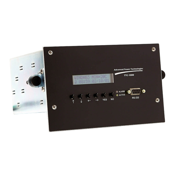
2.1 Controls & Indicators Figure 2.1a and 2.1b show the front panel displays, indicators, and switches for both panel mount and NEMA 4 versions: Advanced Power Technologies TTC-1000 CLEAR WINDOW NO TEXTURE ALARM... - Page 12 UP arrow button for navigating forward into menu categories and increasing settings. DOWN arrow button for navigating backward into menu categories and decreasing settings. LEFT arrow button used for moving to the next character to the left when changing settings. RIGHT arrow button used for moving to the next character to the right when changing settings.
-
Page 13: Connection Overview
2.2 Connection Overview The Figure 2.2 describes the available connections. O U T 4 C O M O U T 3 C O M TTC-1000-XXX O U T 2 C O M O U T 1 C O M Probe #1... -
Page 14: Specifications
2.3 Specifications Power Supply Input Operating Range: 38 VDC to 160 VDC or 120VAC ±10%, 3 Watts max Operating Temperature Range: -35 °C to +85 °C Liquid Temperature Measurement Range: 0 °C to +160 °C LTC Differential Temperature Measurement Range: -20 to +20 °C Winding Temperature Measurement Range: 0 to 180 °C... - Page 15 NEMA 4X: 10” H x 6” W x 3.25” D. 304 Stainless Steel Surge Withstand/Fast Transient: Relay outputs, and station battery inputs: ANSI C37.90.1 EMI Withstand: ANSI C37.90.2 Dielectric Withstand: 1500 VDC for 10 seconds Electrostatic Discharge: IEC 801-2 Timers: Output and Load Pick Up Timer: 0 to 255 seconds (actual minimum delay 32 msec) Optically Isolated Inputs:...
-
Page 16: Part Number Details
2.4 Part Number Details TTC- 1000- Panel Mounting 0 4 form C Outputs, No inputs NEMA 4X Enclosure 3 6 form C Outputs, No inputs NEMA 4X w/Heater 4 4 form C Outputs, 2 inputs 3 6 form C Outputs, 2 inputs No telemetry outputs 0 Single Probe Single analog output... -
Page 17: Installation And Connections
NEMA 4X for mounting either inside or outside the control cabinet. Figure 3.1 shows the outline & cutout required for panel mounting. 5.70 in. Advanced Power Technologies TTC-1000 CLEAR WINDOW NO TEXTURE 2.83 in. -
Page 18: Figure 3.2: Nema 4X Mounting
Figure 3.2 shows the outline of the NEMA 4X enclosure. A mounting bracket, P/N:80001000126, suitable for retrofit or new applications is shown in Figure 3.3. The bracket is constructed from 1/8” THK 5052 Aluminum. Oblong 0.312 X 0.500 5.00 Lexan Window 13.0”... -
Page 19: Power Hookup
TB1. On NEMA units (Figure 3.4b) power is connected to terminals 1 and 2 on TB-3. The TTC-1000 is not sensitive to polarity because it uses a bridge rectifier on the power input. This feature eliminates the risk of damage due to the reversal of power applied to this input. -
Page 20: Ttc-Probe-01 Installation
thermometer well adapter fittings: 7/8-UNF (ANSI/IEEE C57 thermometer well), ½-NPT and ¾-NPT and three probe sleeves: 0.481, 0.625 and 0.675 OD. Temperature probes are interchangeable and do not require calibration. The temperature probes and measurement circuitry are intrinsically accurate to the stated accuracy specification. -
Page 21: Ttc-Probe-11 Installation
5. Close the elbow, forming a 90 degree right angle. Tighten the domed strain relief until the insert is tight against the probe cable. 3.3.2 TTC-PROBE-11 Installation Probe type TTC-PROBE-11 allows coupling of flexible conduit directly to the thermometer well adapter fittings provided. Its unique design allows the probe to be held in the well. -
Page 22: Figure 3.7: Magnetic Mount, Application Of Thermal Compound
RTV silicone sealant suitable for the outdoor applications and rated for the maximum operating temperature. Thermal grease (supplied with probe). To install the probe: 1. Coat center probe area with a liberal coating of thermal grease as shown in Figure 3.7. Apply a liberal coating of Thermal Grease Figure 3.7: Magnetic Mount, Application of Thermal Compound... -
Page 23: Figure 3.8: Magnetic Mount, Side View
Tank Wall Figure 3.8: Magnetic Mount, Side View 3. Place a bead of RTV silicone or other suitable sealing compound around the perimeter of the probe to seal the probe surface from moisture. See Figure 3.9. V1.00, August 30, 2004... -
Page 24: Probe Lead Connections
RTV Seal Tank Wall Figure 3.9: Magnetic Mount, Application of RTV 3.3.4 Probe Lead Connections The probe leads are color-coded and are inserted into the terminal block in the following sequence: Probe Panel Marking Wire Color Terminal # White Black White Black White... -
Page 25: Figure 3.10: Probe Connections
250 feet. Also it is important to ensure that the TTC-1000’s chassis is grounded to a point close to where the shield drain wire terminates as shown in Figure 3.11. -
Page 26: Auxiliary Ct Input For Calculated Winding Temperature
Figure 3.11: Temperature Probe Shield Grounding 3.4 Auxiliary CT Input for Calculated Winding Temperature Models TTC-1000-xx3x and TTC-1000-xx4x are equipped with an auxiliary CT input. A split core CT is supplied with these models and is intended to be applied over the secondary leads from the bushing CT. -
Page 27: Cooling Control And Condition Alarm Connections
A u x C T P o w e r T B 3 T B 2 T B 1 A u x C T P o w e r a ) P a n e l M o u n t b ) N E M A 4 Figure 3.13: Auxiliary CT Connections WARNING: SEVERE DAMAGE WILL RESULT IF THE SECONDARY LEADS... -
Page 28: Unit Alarm Connections
S H I E L D T B 3 O U T 4 O U T 3 O U T 2 O U T 1 a) Panel Mount T B 1 N C C N C C N C C O U T 4 O U T 3 O U T 2... -
Page 29: Telemetry Connections
The TTC-1000 monitors five conditions: Processor (DEVICE), Temperature (TPROBE), Winding (WNDG), Communications Processor (CPROC) and Manual Mode (MANUAL). The TTC-1000 allows the user to enable or disable any or all of the alarm conditions, except the Communications Processor alarm, through programming. -
Page 30: Analog Outputs
A jumper, J2, can be selectively installed if the TTC-1000 is either the first or last device on the two wire communications bus. Figure 3.18 illustrates the location of J2 on the Communications Processor Module. -
Page 31: Figure 3.18: Location Of J2 Rs-485 Bus Termination Jumper
T B 4 Figure 3.18: Location of J2 RS-485 Bus Termination Jumper NOTE: For panel mount versions, the unit contains the jumper but it is not installed. To install jumper J2, the unit must be disassembled. The Relay Board must be removed to gain access to the Communications Processor Module. -
Page 32: Optically Isolated Inputs
PROBE #1 PROBE #2 ALARM T B 4 a) Panel Mount b) NEMA 4 Figure 3.19: Panel Mount and NEMA 4 RS-485 Connections Tx Tx Rx Rx Figure 3.20: Four Wire RS-485 Connections There are many good references on implementing multi-drop RS-485 communication links from the semiconductor divisions of Texas Instruments, National Semiconductor, and MAXIM Integrated Products. -
Page 33: Heater Connections
Figure 3.21: Optically Isolated Input Connections 3.9 Heater Connections NEMA 4X Models, TTC-1000-4XX, are equipped with a 13 Watt thermostatically controlled heater and a specially designed vent that allows moisture to escape and does not allow moisture to re-enter. The heater can be operated from DC voltages of 38 to 160 or at 120 VAC. -
Page 34: Settings
Windows Terminal, HyperTerminal and Procomm. For settings through a PC you will need a female to male DB-9 null modem cable. The TTC-1000 is fixed to communicate at 9600 bits/sec with 8 bits, no parity and one stop bit. - Page 35 emulation be set for either ANSI or TTY. The pin out of this port is designed to use a 9 pin female to 9 pin male null modem cable. You will need to configure your terminal emulation program before you get started. Press the “Enter”...
- Page 36 51 OUT2 AUTO (0) 52 OUT2 SUPVS (2) w/ALRM 53 OUT3 PICKUP TMR=00 sec 54 OUT3 AUTO (0) 55 OUT3 UNCHG (0) w/ALRM 56 OUT4 PICKUP TMR=00 sec 57 OUT4 AUTO (0) 58 OUT4 UNCHG (0) w/ALRM 59 SP11 + TO OUT1 60 SP12 + TO OUT2 61 SP13 + TO OUT3 62 SP14 Not Assigned...
-
Page 37: Settings For Calculated Winding Temperature
115 WNDCKT ALRM ENABLED (0) 116 DEVICE ALRM ENABLED (0) 117 TEMPERATURE ALRM ENABLED (0) 118 MANUAL ALRM ENABLED (0) 119 TIME SP CNTR=00 120 PASSWORD=0000 Enter Code: 4.3 Settings for Calculated Winding Temperature Models equipped with the Aux CT input are supplied with a split core CT which is snapped over the secondary leads from the bushing CT. -
Page 38: Ct Ratio
= Measured Top Oil temperature TopOil It is noted that the Hot Spot Rise over Top Oil at rated load is not always available. In this case we recommend subtracting the Top Oil Rise from the average conductor rise at rated load and add between 18 to 22 ºC to the difference to obtain the hot spot rise over top oil at rated load. -
Page 39: Rated Load
4.3.2 Rated Load The Rated Load setting is the top name plate rating in Amps. If the nameplate indicates ratings of 1000/1200/1400, use 1400 as the rated load. On some transformers the nameplate might only list the rating in MVA. In this case you will need to divide the top MVA rating by the voltage of winding monitored with the CT. -
Page 40: Winding Rise Time Constant
Enter:94/20) This will program the hot spot rise to 20 degrees Celsius. 4.3.4 Winding Rise Time Constant The Winding Rise Time Constant is the amount of time, in minutes, for the winding hot spot temperature to reach 67 percent of its final value. A number of factors including the volume and type of oil used and the mass of the transformer are factors that influence this setting. -
Page 41: Checking Winding Temperature
Enter:80/1) This will program the Cooling Type to directed FOA/FOW. Enter 0 for all other cooling types. 4.3.6 Checking Winding Temperature A built in WNDGCAL test function is provided to verify proper operation of the calculated winding temperature function. All settings described in Sections 4.3.1 through 4.3.5 must be made before performing this check. - Page 42 AMBIENT LTCDIFF BOTMOIL TOPOIL1 TOPOIL2 TOPOIL3 LTCDIF1 LTCDIF2 NOTE: The MIN/MAX log should always be reset after changing probe names. This is especially critical for the LTCDIFF as its range is different from the TOP OIL, WINDING, BOTMOIL and AMBIENT temperatures. &...
-
Page 43: Temperature Set Points
Enter:98/3) 4.5 Temperature Set Points The TTC-1000 has four independent temperature set points per temperature probe and four calculated winding set points. Three probe units with calculated winding temperature have a total of 16 temperature set points. Each set point has its own pick up and drop out temperatures. -
Page 44: Figure 4.1: Over Temperature Operation
Temperature SPpn Pick Up Temperature SPpn Drop Out Temperature Time S P p n Figure 4.1: Over Temperature Operation V1.00, August 30, 2004... -
Page 45: Figure 4.2: Under Temp Operation
Temperature SPpn Drop Out Temperature SPpn Pick Temperature Time S P p n Figure 4.2: Under Temp Operation Once a set point has picked up, it will not drop out until the pre-programmed conditions are met. This feature is especially useful to allow the fans to continue to run until the top oil temperature drops to some lower temperature. -
Page 46: Setting Liquid Pickup And Drop Out Temperatures
1. When changing pickup or drop out temperature set points, the new value takes effect the next time temperature data is updated which occurs every 16 seconds. However, once a SP is picked up, changing the pickup temperature to a higher (if over temperature) or lower (if under temperature) value will not cause the SP to drop out. -
Page 47: Setting Calculated Winding Pickup And Drop Out Temperatures
% % % % The remaining liquid set points can be changed by pressing the arrow button and following the above procedure. For programming from a PC just type the desired temperature on the “Enter:” line as follows: Enter:1/75) This will program SP11 pickup to 75 C. Enter:2/70) This will program SP11 drop out to 70 C. -
Page 48: Ltc Condition Monitoring
This will program WSP1 pickup to 85 C. 4.6 LTC Condition Monitoring The TTC-1000 has up to two set points that the user can employ for LTC conditioning monitoring. The LTC differential, or LTCDIFF, is the mathematical difference between the LTC tank and top oil temperatures and therefore is only available in dual temperature probe units. - Page 49 The TTC-1000 uses an LTC pickup timer settable from zero to 999 minutes to supervise the LTC set point. The above example shows that the LTCDIFF set point does not pickup until after the timer is complete. If the differential temperature drop down below the pick up temperature while the timer is in progress, the timer will reset.
-
Page 50: Setting Ltcdiff Set Point
NOTE: 1. In single probe versions, the LTCDIFF pickup and dropout settings display “N/A”. 2. Be careful to check that the LTCDIFF pickup and dropout set points are never set to greater than 20 or less than –20. Erroneous operation of the LTCDIFF pickup or dropout will result if these set points are set beyond the stated range. -
Page 51: Setting Ltcdiff Pickup Timer
4.6.2 Setting LTCDIFF Pickup Timer Programming LTCDIFF1 and LTCDIFF2 pick up timers from the front panel, % % % % & & & & press the arrow buttons until the setting 042 is displayed: PRGM SETTING 042 LTCPUTMR1=480MIN % % % % &... -
Page 52: Figure 4.4: Load Pickup Set Point Operation
LOAD Load Pick Up Current Load Drop Out Current Time Timer Resets Load Pickup Timer Load Pickup Set Point Figure 4.4: Load Pickup Set Point Operation The first case shows that the load current remains above the pickup set point for the full duration of the load pickup timer. -
Page 53: Setting Load Pickup Set Point
4.7.1 Setting Load Pickup Set Point These settings are used to start a stage of cooling based on a sudden increase in load current. Two set points LSP1 and LSP2 are available to start up to two stages of cooling. As with temperature set points, load set points can be configured to operate in under current mode. -
Page 54: Setting Load Pickup Timer
This will program the Load pickup timer to 120 seconds. 4.8 Optically Isolated Input Settings The TTC-1000 may be optionally equipped with two optically isolated inputs. Each input contains a limiting resistor that allows these inputs to recognize a wide range of input voltage of 38 to 160 VDC as being picked up. Inputs are scanned every 32 milliseconds. -
Page 55: Figure 4.5: Input Set For Level
Signal Applied to Input n Debounce Timer Figure 4.5: Input Set for LEVEL Signal Applied to Input n Debounce Timer Figure 4.6: Input Set for PULSE % % % % Programming from the front panel, press the arrow button until the setting 050 is displayed: PRGM SETTING 050 I N 1 = L E V E L... -
Page 56: Programmable Logic Settings
Also, these specific operands can be either AND’ed (!) or OR’ed (+) to a specific output. In evaluating a specific output, the TTC-1000 groups all of the OR’ed terms together and all of the AND’ed terms together. As an... -
Page 57: Assigning Liquid Temperature Set Points
This is particularly useful for fail safe operation. NOTE: Fail safe operation is strongly recommended. Fail safe operation ensures that the cooling system picks up whenever the TTC-1000 becomes de-energized or encounters a failure. Fail safe requires the output relay controlling the cooling stage to drop out instead of picking up. - Page 58 NOTE: DO NOT ASSIGN SP21, SP22, SP23, SP24, or SP31,SP32,SP33,SP34 IF ASSIGNING THE LTCDIFF SET POINT. To assign a liquid set point (SP11, SP12, SP13, SP14, SP21, SP22, SP23, % % % % SP24, SP31, SP32, SP33, SP34) to an output from the front panel, press the &...
-
Page 59: Assigning Winding Temperature Set Points
For programming from a PC just type the SP11 assignment on the “Enter:” line as follows: Enter:59/0/1/1) This will assign SP11 Or’ed to OUT1. To assign !SP11 And’ed OUT1: Enter:59/1/0/1) Consult the setting sheets to assign the remaining temperature set points SP12 through SP24. -
Page 60: Assigning Ltcdiff For Ltc Condition Monitoring Alarm
' ' ' ' ( ( ( ( Use the buttons to scroll to the output #. The output number will flash. % % % % & & & & Use the arrow buttons to scroll from 0 to 4. Setting the output number to zero will have the effect of de-assigning the set point. - Page 61 ' ' ' ' ( ( ( ( Use the buttons to scroll to the AND/OR logic operator. The operator will % % % % & & & & flash. Use the arrow buttons to scroll between the and + operators. Selecting will AND LTC with any other set point or operand controlling the same output.
-
Page 62: Assigning Load Pickup Set Points
4.9.4 Assigning Load Pickup Set Points Load pickup set points must be assigned to a specific output to start a stage of cooling based on a sudden increase in load current. To assign a load pickup set % % % % &... -
Page 63: Assigning In1 And In2
% % % % LSP2 can be assigned by pressing the arrow button and following the above procedure. For programming from a PC just type the LSP1 assignment on the “Enter:” line as follows: Enter:77/0/1/1) This will assign LSP1 OR’ed to OUT1. To assign !LSP1 And’ed OUT1: Enter:77/1/0/1) Consult the setting sheets to assign LSP2. -
Page 64: Assigning Out1, Out2, Out3 And Out4
PRGM SETTING 076 IN1 + TO OUT0 ' ' ' ' ( ( ( ( Use the buttons to scroll to the output #. The output number will flash. % % % % & & & & Use the arrow buttons to scroll from 0 to 4. Setting the output number to zero will have the affect of de-assigning the set point. - Page 65 % % % % & & & & The first character is the inversion operator. Use the arrow buttons to scroll between the inversion operator, !, and a blank space. While the inversion operator is displayed, the ! character will flash. PRGM SETTING 078 ! OUT1 TO OUT0 ' ' ' '...
-
Page 66: Time Set Points
4.9.7 Time Set Points The time set points allow the user additional flexibility to activate events between specific times. There are three time set points available. Time set points are useful to exercise a bank of fans periodically. For example, the user can set the device to pick up an output at 03:00 hours and drop out at 04:00 hours. - Page 67 The following shows TSP1 set to pickup output 1 at 14:00 and drop out output 1 after 14:15: PROGRAM TSP1 082 1 4 : 0 0 - 1 4 : 1 5 > O U T 1 TSP2 and TSP3 are set using the same procedure described above. For programming from a PC just type the TIME1 setting and assignment on the “Enter:”...
-
Page 68: Setting Output Timers
This is particularly useful for fail safe operation of the controller. Fail safe operation is highly recommended as it allows your cooling system to be activated should the TTC-1000 become de-energized or a device or temperature probe alarm is detected. Fail safe operation is achieved by ensuring the output relay drops out when the necessary set points are satisfied to command a stage of cooling. -
Page 69: Application Examples
% % % % & & & & Press the YES button. The first character will flash. Use the arrow buttons to scroll between OFF and ON. Selecting ON will invoke the overall invert function. Press YES when you have made the correct selection. INVERT OUT2, INVERT OUT3, and INVERT OUT4 can be selected by pressing % % % % arrow button and following the above procedure. - Page 70 NOTE: Do not use the inversion operator on individual set points when remote control through DNP3.0 and fail-safe cooling control is desired. The INVERT setting must be used on each output requiring fail-safe cooling control when remote cooling control through DNP3.0 is required. The use of the inversion operator on a set point will not be recognized by the remote control functions resulting in the cooling to be de-energized.
- Page 71 Use the INVERT OUTn setting to cause the output relay to drop out when either temperature set point is achieved. The resulting Boolean equation is: = !(Temperature Set Point + Temperature Set Point Periodic exercise of cooling fans: Use a time set point with the temperature set point, controlling the cooling fans, to exercise the fans on a daily basis.
-
Page 72: Setting Output Control With Alarm
All temperature set point evaluations are suspended until the alarm condition is cleared. The TTC-1000 allows you to program how an output will react whenever there is a DEVICE or TPROBE alarm. There are three (3) ways an output can react whenever there is a DEVICE or TPROBE alarm: 1. -
Page 73: Alternate Fan Banks
Consult the setting sheets to change output control for OUT2, OUT3, and OUT4. 4.11 Alternate Fan Banks The TTC-1000 can be programmed to alternate the energization between two outputs. This feature is particularly useful when it is desirable to insure a fan bank is regularly exercised. -
Page 74: Auto And Manual Control
RS-232 interface. The TTC-1000 will cause the Device Alarm contacts to pick up when an output is put into the manual mode. In addition the ALARM LED on the front panel will illuminate. -
Page 75: Setting Control Of Unit Alarm
The TTC-1000 monitors five conditions: Processor (DEVICE), Temperature (TPROBE), Manual Mode (MANUAL), Winding (WNDCKT), DNP3.0 Communications (CPROC). The TTC-1000 allows the user to enable or disable all of the alarm conditions, except the DNP3.0 Communications (CPROC), through programming. V1.00, August 30, 2004... -
Page 76: Device Alarm Setting
4.13.1 Device Alarm Setting A DEVICE alarm occurs anytime the microprocessor detects a failure in any of the peripheral hardware including the non-volatile E memory, the real time clock, analog outputs or corruption of stored data. % % % % &... -
Page 77: Manual Mode Alarm Setting
Press YES when you have made the correct selection. Selecting DSABL will block the device alarm relay and the front panel alarm LED from illuminating. PRGM SETTING 110 TPROBEALRM=DSABL However, the front panel will display the alarm if present. For programming from a PC just type the setting for temperature probe alarm enable on the “Enter:”... -
Page 78: Setting Date And Time
This will disable the winding circuit probe alarm. Type 0 to enable the alarm. 4.14 Setting Date and Time The TTC-1000 utilizes a real time clock to maintain date and time. This device has two functions. It supplies precise 32 millisecond time ticks for the Real Time Interrupt and it keeps track of the time, date and day of the week. -
Page 79: Setting Time And Date Via The Front Panel
4.14.1 Setting Time and Date Via the Front Panel % % % % & & & & Setting from the front panel, press the arrow button until the setting 105 is displayed: PRGM SETTING 105 TIME=00:05 % % % % &... -
Page 80: Setting Time And Date Via The Pc
% % % % & & & & Press the YES button. The 10’s year digit will flash. Use the arrow buttons ( ( ( ( to set this digit. Use the button to move to the 1’s year digit and observe that % % % % &... - Page 81 It is important to remember to enter the password as a four digit number. Failure to enter a four digit number will result in an incorrect password. V1.00, August 30, 2004...
-
Page 82: Telemetry Options
TTC-1000. The TTC-1000 implements DNP3.0 Level 1 communications. This includes Class 0 polls (Object 60 Variation 1) of analog and binary output points. The TTC-1000 supports Object 1 Variation 2 binary outputs. Binary outputs include all temperature and load set points along with the state of each output relay. - Page 83 Also, the TTC-1000 uses two points to identify whether or not the probe is measuring Top Oil, Heated Well, LTC Differential or Ambient temperature. This is particularly useful for dual probe units. It is noted that Object 1 Variation 2 and Object 30 Variation 4 points cannot be read individually and can only be read by a Class 0 poll.
-
Page 84: Setting Baud Rate
implementation is that the top priority of the Main microprocessor is for control and monitoring and the Communications Processor is to receive potentially high- speed request messages from the DNP Master and to respond to these requests without delay. While higher polling rates are possible, it is highly recommended that the polling rate be between 1,000 to 10,000 milliseconds, but should be no faster than 500 milliseconds. -
Page 85: Setting Remote Blocking
To change this setting, enter PROGRAM mode from the front panel as discussed % % % % in Section 4.1. To set the node address from the front panel, press the & & & & arrow button until the setting 097 is displayed: PRGM SETTING 097 NODE ADDR=00000 % % % %... -
Page 86: Telemetry Via Rs232
Where the first temperature is probe #1 and the second is probe #2. Sending the string /R) causes the TTC-1000 to reset the real time clock to 00:00:00 hours. The date is not changed. It is noted that the characters /R are echoed back to the host computer. -
Page 87: View Temperatures
VIEW TEMPERATURES The temperature & time display will be the first display you see upon power up. Date, time, and temperature are updated when fresh data is available. The display will continuously scroll through a set sequence. The sequence will depend on the number of liquid temperature probe channels and if the unit is equipped to measure calculated winding temperature. -
Page 88: Dual Probe
6.2 Dual Probe For dual probe units, model number –XX2X the display sequence will appear as follows: 07/29/03 13:15 P1 TOP OIL 45 C 07/29/03 13:15 P2 WINDING 58 C TOP OIL MIN= 35 C @ 03:15 07/29/03 TOP OIL MAX= 65 C @ 17:42 07/18/03 WINDING MIN= 43 C @ 03:15 07/29/03... -
Page 89: Three Probe
6.3 Three Probe 07/29/03 13:15 RST MIN/MAX P1 TOPOIL1 45 C P U S H Y E S T O R S T 07/29/03 13:15 TOPOIL3 MAX= 64 C P2 TOPOIL2 47 C @ 17:42 07/18/03 07/29/03 13:15 TOPOIL3 MIN= 34 C P3 TOPOIL3 46 C @ 03:15 07/29/03... -
Page 90: Single Probe With Calculated Winding
6.4 Single Probe With Calculated Winding For single probe units with calculated winding temperature, model number – XX3X the display sequence will appear as follows: 07/29/03 13:15 P1 TOP OIL 45 C 07/29/03 13:15 WINDING 58 C 07/29/03 13:15 LOAD 453 A TOP OIL MIN= 35 C @ 03:15 07/29/03... -
Page 91: Dual Probe With Calculated Winding
6.5 Dual Probe With Calculated Winding For dual probe units with calculated winding temperature, model number –XX4X the display sequence will appear as follows: 07/29/03 13:15 07/29/03 13:15 P1 TOP OIL 45 C P2 LTCDIFF - 03 C 07/29/03 13:15 07/29/03 13:15 LOAD 453 A... -
Page 92: Reset Min/Max
6.6 Reset Min/Max The minimum and maximum registers may be reset by pressing the YES button when the display is showing: RST MIN/MAX P U S H Y E S T O R S T To confirm that the min/max values are reset, the display will read: MIN/MAX IS RST New data will be recorded as soon as the data is ready. -
Page 93: View Settings
VIEW SETTINGS View allows display of settings without entering PROGRAM. Settings may be viewed from the front panel or via a PC. 7.1 View Settings Via Front Panel % % % % & & & & To view settings from the front panel, first press the arrow buttons until the VIEW Settings screen is displayed: VIEW SETTINGS... - Page 94 33 LTCDIFF1 PICKUP=05 øC 34 LTCDIFF1 DRPOUT=00 øC 35 LTCDIFF2 PICKUP=05 øC 36 LTCDIFF2 DRPOUT=00 øC 37 LTCDIFF PICKUPTMR1=480 38 LTCDIFF PICKUPTMR2=480 39 LSP1 PICKUP=4.0 A 40 LSP1 DRPOUT=3.5 A 41 LSP2 PICKUP=5.0 A 42 LSP2 DRPOUT=4.5 A 43 LOAD PICKUP TMR1 =180 sec 44 LOAD PICKUP TMR2 =120 sec 45 IN1 CTRL=LEVEL (0) 46 IN2 CTRL=LEVEL (0)
- Page 95 118 MANUAL ALRM ENABLED (0) 119 TIME SP CNTR=00 After transmitting the data to the host computer, the TTC-1000 automatically logs off. The user must press the Enter key to re-display the Main Menu. NOTE: In single probe units, TEMP PROBE2 NAME=N/A.
-
Page 96: Status
STATUS STATUS allows you to take a snapshot of the recognized state of any output, temperature set points, LOAD, LTCDIFF set points, time set points and optically isolated inputs. In the case of outputs, this will be the state of the programmable logic. - Page 97 WSP4=PICKED UP LSP1=PICKED UP LSP2=PICKED UP IN1=DRP'D OUT IN2=DRP'D OUT OUT1=PICKED UP OUT2=DRP'D OUT OUT3=DRP'D OUT OUT4=DRP'D OUT TIME1=DRP'D OUT TIME2=DRP'D OUT TIME3=DRP'D OUT You must press the Enter key on your keyboard to display the Main Menu. V1.00, August 30, 2004...
-
Page 98: Setting Files
SETTING FILES Uploading and downloading of setting files can only be accomplished through connection from a PC directly connected to the TTC-1000. To save a setting file on your PC use Upload Setting file. To transfer a previously stored setting file from your PC to the TTC-1000, use Download Setting file. - Page 99 2. After pressing 4 and Enter: 3. Click on Transfer and click Receive File: V1.00, August 30, 2004...
- Page 100 4. Select from the Use receiving protocol list box Xmodem protocol. If the folder listed is incorrect, click Browse to select the folder where the received setting file is to be placed. Click Receive: 5. Enter the file name and click OK: V1.00, August 30, 2004...
- Page 101 6. Uploading will begin. There will be two retries. Click Cancel if more than 3 retries are attempted: 7. At the conclusion of the upload, the Main Menu will display. NOTE: Upload can be terminated by pressing the Esc key on your PC prior to starting the file transfer.
-
Page 102: Upload Settings Using Procomm
9.1.2 Upload Settings Using Procomm The procedure to upload a setting file is as follows: 1. Press Enter to display the Main Menu. Press 4 and then Enter: V1.00, August 30, 2004... - Page 103 2. Click on Data. Click on Receive File: V1.00, August 30, 2004...
- Page 104 3. Select a folder and Type the file name. Click Save: V1.00, August 30, 2004...
- Page 105 2nd, 3rd or 4th try as both programs automatically switch to Check Sum error checking. The TTC-1000 has a built in 60 second delay to wait for retries. Should you wish to abort the reception, close all active terminal emulation receive windows and press the ESC key followed by the Enter key on your PC.
-
Page 106: Download Setting Files
9.2 Download Setting Files Download settings transfers the binary setting file on your PC to the TTC-1000 connected through the RS232 communications port. The TTC-1000 uses the XMODEM protocol which is supported by HyperTerminal and Procomm, as well as other terminal emulation programs. Check sum error checking is employed. - Page 107 2. Click Transfer then click Send File: 3. Select the Folder by clicking Browse to locate folder where the file is to be stored and enter the file name. Select Xmodem protocol: V1.00, August 30, 2004...
- Page 108 4. The following screen will show the download progress: 5. If successful, the following screen will display: NOTE: Download may be terminated prior to the transfer by pressing any key on the keyboard V1.00, August 30, 2004...
-
Page 109: Download Settings Using Procomm
9.2.2 Download Settings Using Procomm Check settings to insure Xmodem protocol is selected. To download a setting file: 1. Press Enter to display the Main Menu and type 5 followed by / followed by the 4 digit password: V1.00, August 30, 2004... - Page 110 2. Click Data and click Send File: 3. Select Folder, type file name and click Open: V1.00, August 30, 2004...
- Page 111 4. Progress will be indicated: 5. The following screen will be displayed when complete: V1.00, August 30, 2004...
- Page 112 NOTE: The TTC-1000 will suspend all measurements and calculations once downloading is selected. The outputs will also be blocked during this time. The TTC-1000 transfers the new settings to a buffer register and will transfer the settings to E memory only after the checksum test is passed.
-
Page 113: Data Logging
10 DATA LOGGING Data logging permits storage of time stamped temperature and load data. The user has the ability to change the time base used for time stamping from 1 to 9999 seconds. Setting the time base to zero erases the log and prevents records from being recorded. -
Page 114: Data Points
There is one limitation, in the event that power is interrupted, the time stamp is stored as a data record. Time stamp records consume a total of 8 bytes. This is a non-factor if power is never interrupted, but if the device is AC powered, it could reduce the number of records by a small amount. -
Page 115: Selecting Data Points
10.4 Selecting Data Points Any or all of the data points can be selected for logging. Change the number of points or the points recorded will erase the log. If no points are selected the log will be erased and no data logged. There are four points that can be added to the log: P1, P2, Calculated Winding, and Load. -
Page 116: Add Or Delete P3 From Log
Enter:109/1) This will add P2 to the log. Type 0 to remove from the log. 10.4.3 Add or Delete P3 From Log To change this setting, enter PROGRAM mode from the front panel as discussed % % % % in Section 4.1. To set the P3 RECORD from the front panel, press the &... -
Page 117: Add Or Delete Load From Log
10.4.5 Add or Delete Load From Log To change this setting, enter PROGRAM mode from the front panel as discussed % % % % in Section 4.1. To set the LOAD RECORD from the front panel, press the & & & & arrow button until the setting 104 is displayed: PRGM SETTING 104 LOADRECORD =NO... -
Page 118: Retrieving Data Log
9 pin female to 9 pin male null modem cable. You will need to configure your terminal emulation program before you get started. First press the Enter key to display the Main Menu: Advanced Power Technologies, LLC; (C) 2001-2003 Transformer Temperature Controller V4.3XX Select: 1. VIEW 2. -
Page 119: Saving The Data Log As A Text File Using Hyperterminal
END OF REPORT. STOP TEXT CAPTURE & PRESS 'Enter' The first line is the header for the data reported. The last character is a carriage return (CR) character, hex 013, and line feed (LF), hex 011. Each subsequent line is the comma delimited data followed by a CR and LF characters. 10.5.1 Saving the Data Log as a Text File Using HyperTerminal To save the data log in HyperTerminal: 1. - Page 120 3. Click on Capture Text. A window will open to select the Folder where the text file is to be stored: 4. Click Browse to find a Path to store the download and enter a file name and click the Save button: V1.00, August 30, 2004...
- Page 121 5. Press enter after the 6 in the Main Menu: 6. Click on Transfer, Capture Text and click Stop to halt the data capture: V1.00, August 30, 2004...
-
Page 122: Saving The Data Log As A Text File Using Procomm
10.5.2 Saving the Data Log as a Text File Using ProComm 1. Press 6 on the Enter line of the Main Menu and press the Enter key: V1.00, August 30, 2004... - Page 123 2. Highlight the data from the screen to be stored as a text file: V1.00, August 30, 2004...
- Page 124 3. Select the Path and file name for the text file. Click Save: V1.00, August 30, 2004...
-
Page 125: Import To Excel
10.6 Import to Excel The text file captured can be imported into excel for plotting and sorting. It is a good idea to open the text file in Notepad to delete any extra characters before trying to import the file into excel. 1. - Page 126 2. Go to the Path where the text file is stored and select Files of Type: Text Files, Double Click the file name and Click Open: 3. Click the Delimited button and click Next: V1.00, August 30, 2004...
- Page 127 4. Check the Comma box in Delimiters. Make sure all other boxes are unchecked: 5. Click the General button in the Column data format and click Finish: V1.00, August 30, 2004...
- Page 128 6. After closing the import wizard, the text data will display: The data is now ready for graphing. V1.00, August 30, 2004...
-
Page 129: Download Program Updates
11 DOWNLOAD PROGRAM UPDATES The TTC-1000 firmware contains a boot loader that allows the user to download new firmware. Downloading firmware will erase the data log. Firmware can be downloaded to a PC through the RS-232 interface. Firmware patches must be obtained from Advanced Power Technologies and are only available for units with TTMV4.XX firmware. -
Page 130: Download Firmware Using Hyperterminal
The user has approximately 90 seconds to find the file and start the download process. The user will see the following message on the PC if they are unable to locate the file in the allotted time: FIRMWARE FILE TRANSFER IN PROGRESS. PRESS Any KEY TO ABORT. §§§§§§§§§§§§§§§§§§§§§§§§§§§§§§§§§§§§§§§§§§§§§§§§§§§§§§§§§§§§§§§§... - Page 131 2. Find the Path and file name. 90 seconds are allotted to find the file: 3. Select Xmodem from the Protocol pull down list. Enter the Filename if in the Folder indicated or click the Browse button to find the file: V1.00, August 30, 2004...
- Page 132 4. Click on the file name and click open. Click Send: 5. The download will now begin. Clicking Cancel aborts the transfer: V1.00, August 30, 2004...
- Page 133 6. If the transfer is successful, the following screen will be displayed to wait 15 seconds for the transfer to be “burned-in” to the microprocessor: 7. Press the Enter key after 15 seconds to display the Main Menu: 8. If the Main Menu does not appear, check the front panel display to see if the display is scrolling.
-
Page 134: Download Firmware Using Procomm
11.2 Download Firmware Using Procomm Make sure the Transfer Protocol is set for XMODEM. To download firmware using Procomm: 1. Click Data on the toolbar and click Send File: V1.00, August 30, 2004... - Page 135 2. Find the folder containing the file to be transferred. V1.00, August 30, 2004...
- Page 136 3. Click Open: V1.00, August 30, 2004...
- Page 137 4. The download will now begin. Clicking Cancel aborts the transfer: V1.00, August 30, 2004...
- Page 138 5. If the transfer is successful, the following screen will be displayed to wait 15 seconds for the transfer to be “burned-in” to the microprocessor: V1.00, August 30, 2004...
- Page 139 6. Press the Enter key after 15 seconds to display the Main Menu: 7. If the Main Menu does not appear, check the front panel display to see if the display is scrolling. If not de-energize the unit and re-energize. Wait 15 seconds.
-
Page 140: Settings Worksheets
12 SETTINGS WORKSHEETS The following worksheet is a comprehensive list of all the settings programmable through the RS-232 interface and possible settings. A blank space is provided to write-in the desired setting: V1.00, August 30, 2004... -
Page 141: Front Panel Setting Sheets
12.1 Front Panel Setting Sheets Setting # Setting Purpose Setting Range or Factory Program to Values Default SP11PICKUP Probe #1 pickup 0 to 160 C temperature SP11DRPOUT Probe #1 dropout 0 to 160 C temperature SP12PICKUP Probe #1 pickup 0 to 160 C temperature SP12DRPOUT Probe #1 dropout... - Page 142 Setting # Setting Purpose Setting Range or Factory Program to Values Default SP24DRPOUT Probe #2 dropout 0 to 160 C temperature SP31PICKUP Probe #3 pickup 0 to 160 C temperature SP31DRPOUT Probe #3 dropout 0 to 160 C temperature SP32PICKUP Probe #3 pickup 0 to 160 C temperature...
- Page 143 Setting # Setting Purpose Setting Range or Factory Program to Values Default DIRECTED FOA Sets cooling type to YES, NO (functional only in direct FOA/FOW units equipped with WSP1PICKUP Calculated winding set 0 to 180 C point pickup temperature WSP1DRPOUT Calculated winding set 0 to 180 C point dropout...
- Page 144 Setting # Setting Purpose Setting Range or Factory Program to Values Default LTCDIFF2 DO (Not LTC Differential drop out -20 to 20 C functional in single temperature probe units) LTCPUTMR1 (Not LTC Differential pickup 0 to 999 Minutes functional in single timer supervises probe units) LTCDIFF1 pickup...
- Page 145 Setting # Setting Purpose Setting Range or Factory Program to Values Default IN1=LEVEL or Allows input to handle LEVEL or PULSE LEVEL PULSE pulses (functional only in units equipped with optically isolated inputs) IN2=LEVEL or Allows input to handle LEVEL or PULSES LEVEL PULSE pulses...
- Page 146 Setting # Setting Purpose Setting Range or Factory Program to Values Default (!) SP12 (*/+) TO Assigns probe #1 set SP12 * OUT n SP12 * OUTn point to a specific output OUT0 ! SP12 * OUT n using a defined AND or SP12 + OUT n OR logic operator ! SP12 + OUT n...
- Page 147 Setting # Setting Purpose Setting Range or Factory Program to Values Default (!) SP23 (*/+) TO Assigns probe #2 set SP23 * OUT n SP23 * OUTn point to a specific output OUT0 ! SP23 * OUT n using a defined AND or (Not functional in SP23 + OUT n OR logic operator...
- Page 148 Setting # Setting Purpose Setting Range or Factory Program to Values Default (!) SP34 (*/+) TO Assigns probe #3set SP34 * OUT n SP34 * OUTn point to a specific output OUT0 ! SP34 * OUT n using a defined AND or (Not functional in SP34 + OUT n OR logic operator...
- Page 149 Setting # Setting Purpose Setting Range or Factory Program to Values Default (!) WSP3 (*/+) TO Assigns calculated WSP3 * OUT n WSP3 * OUTn winding set points to a OUT0 ! WSP3 * OUT n specific output using a (functional only in WSP3 + OUT n defined AND or OR logic...
- Page 150 Setting # Setting Purpose Setting Range or Factory Program to Values Default (!) IN2 (*/+) TO Assigns optically IN2 * OUT n IN2 * OUTn isolated input to a OUT0 ! IN2 * OUT n specific output using a (functional only in IN2 + OUT n defined AND or OR logic units equipped with...
- Page 151 Setting # Setting Purpose Setting Range or Values Factory Program to Default TIMESETPOINT1 OR's a time range to Pickup and Dropout range: 00:00- a specific output 00:00 to 23:59 (Military 00:00> 00:00-00:00 > time) OUT0 OUT0,1,2,3,4 TIMESETPOINT2 OR's a time range to Pickup and Dropout range: 00:00- a specific output...
- Page 152 Setting # Setting Purpose Setting Range or Factory Program to Values Default P3 NAME Probe #3 name TOP OIL, WINDING, TOP OIL (optional) AMBIENT, LTCDIFF, (only in BOTMOIL, TOPOIL1, dual TOPOIL2, TOPOIL3, probe) LTCDIF1, LTCDIF2 ANALGOUT Current loop current 0to1mA or 4to20mA 0to1mA range A1 SOURCE...
- Page 153 Setting # Setting Purpose Setting Range or Factory Program to Values Default TIME Sets military time HH:MM 00:00 MONTH Sets month 1 to 12 Sets day 1 to 31 YEAR Sets Year 00 to 99 DEVICEALRM Processor alarm enable ENABL for enabled or ENABL DSABL for disabled TPROBEALRM...
- Page 154 Setting # Setting Purpose Setting Range or Factory Program to Values Default OUT3(Action) Allows OUT3 to default OUT3UNCHGw/ALRM OUT3 w/ALRM when a DEVICE or does not allow OUT3 to UNCHG TPROBE alarm change state when w/ALRM Action: UNCHG, alarm PCKUP,SUPV OUT3PCKUPw/ALRM causes OUT3 to pickup when alarm...
-
Page 155: Pc Setting Sheets
12.2 PC Setting Sheets Setting # Setting Purpose Setting Range or Values Program to SP11 PICKUP Probe #1 set point 1/nnn #1 pickup where nnn=0 to 160 temperature SP11 DRPOUT Probe#1 set point#1 2/nnn dropout where nnn=0 to 160 temperature SP12 PICKUP Probe #1, set point 3/nnn... - Page 156 Setting # Setting Purpose Setting Range or Values Program to SP21 DRPOUT Probe #2 set point 10/nnn #1 dropout where nnn=0 to 160 temperature DO NOT SET IF SINGLE PROBE SP22 PICKUP Probe #2, set point 11/nnn #2 pickup where nnn=0 to 160 temperature DO NOT SET IF SINGLE PROBE...
- Page 157 Setting # Setting Purpose Setting Range or Values Program to SP31 DRPOUT Probe #3 set point 18/nnn #1 dropout where nnn=0 to 160 temperature DO NOT SET IF SINGLE OR DUAL PROBE SP32 PICKUP Probe #3 set point 19/nnn #2 pickup where nnn=0 to 160 temperature DO NOT SET IF SINGLE OR...
- Page 158 Setting # Setting Purpose Setting Range or Values Program to WSP1 PICKUP Calculated winding 25/nnn pickup temperature where nnn=0 to 180 SET ONLY IF Aux CT avail. WSP1 DRPOUT Calculated winding 26/nnn dropout temperature where nnn=0 to 180 SET ONLY IF Aux CT avail. WSP2 PICKUP Calculated winding 27/nnn...
- Page 159 Setting # Setting Purpose Setting Range or Values Program to LTCDIFF1 LTC Differential 1 34/-nn or 33/nn DRPOUT drop out where nn=0 to 20 temperature DO NOT SET IF SINGLE PROBE LTCDIFF2 LTC Differential 2 35/-nn or 34/nn PICKUP pickup temperature where nn=0 to 20 DO NOT SET IF SINGLE OR DUAL PROBE...
- Page 160 Setting # Setting Purpose Setting Range or Values Program to LSP2 DRPOUT Load dropout 42/n.n current where n.n=0.0 to 9.9 SET ONLY IF Aux CT avail. LOAD PICKUP Load pickup timer 43/nnn TMR1 for LSP1 where n=0 to 255 seconds SET ONLY IF Aux CT avail.
- Page 161 Setting # Setting Purpose Setting Range or Values Program to OUT2 Operate Output in 51/0: AUTO (uses AUTO/MANUAL AUTO or MANUAL programmable logic control 51/1: MANUAL (control through front panel) OUT2 xxxxx (n) Controls Behavior of 52/0: OUT2 UNCHG (0) w/ALRM output when Device w/ALRM...
- Page 162 Setting # Setting Purpose Setting Range or Values Program to (!) SP11 (*/+) Programmable logic 59/0/0/0: SP11 not assigned TO OUTn for SP11 59/0/0/n: SP11 * to OUTn 59/1/0/n: !SP11 * to OUTn 59/0/1/n: SP11 + to OUTn 59/1/1/n: !SP11 + to OUTn where n=1,2,3,4 (!) SP12 (*/+) Programmable logic...
- Page 163 Setting # Setting Purpose Setting Range or Values Program to (!) SP21 (*/+) TO Programmable logic for 63/0/0/0: SP21 not assigned OUTn SP21 63/0/0/n: SP21 * to OUTn DO NOT USE FOR 63/1/0/n: !SP21 * to OUTn SINGLE PROBE 63/0/1/n: SP21 + to OUTn 63/1/1/n: !SP21 + to OUTn where n=1,2,3,4 (!) SP22 (*/+) TO...
- Page 164 Setting # Setting Purpose Setting Range or Values Program to (!) SP31 (*/+) TO Programmable logic for 67/0/0/0: SP31 not assigned OUTn SP31 67/0/0/n: SP31 * to OUTn DO NOT USE FOR 67/1/0/n: !SP31 * to OUTn SINGLE OR DUAL 67/0/1/n: SP31 + to OUTn PROBE 67/1/1/n: !SP31 + to OUTn...
- Page 165 Setting # Setting Purpose Setting Range or Values Program to (!) LTCDIFF1 Programmable 71/0/0/0: LTCDIFF not (*/+) TO OUTn logic for LTCDIFF1 assigned DO NOT USE FOR 71/0/0/n: LTCDIFF * to OUTn SINGLE PROBE 71/1/0/n: !LTCDIFF * to OUTn 71/0/1/n: LTCDIFF + to OUTn 71/1/1/n: !LTCDIFF + to OUTn where n=1,2,3,4 (!) LTCDIFF2...
- Page 166 Setting # Setting Purpose Setting Range or Values Program to (!) WSP3 (*/+) Programmable 75/0/0/0: WSP3 not assigned TO OUTn logic for WSP3 75/0/0/n: WSP3 * to OUTn SET ONLY IF Aux 75/1/0/n: !WSP3 * to OUTn CT avail. 75/0/1/n: WSP3 + to OUTn 75/1/1/n: !WSP3 + to OUTn where n=1,2,3,4 (!) WSP4 (*/+)
- Page 167 Setting # Setting Purpose Setting Range or Values Program to (!) OUT1 (*/+) Programmable 79/0/0/0: OUT1 not assigned TO OUTn logic for OUT1 79/0/0/n: OUT1 * to OUTn 79/1/0/n: !OUT1 * to OUTn 79/0/1/n: OUT1 + to OUTn 79/1/1/n: !OUT1 + to OUTn where n=1,2,3,4 (!) OUT2 (*/+) Programmable...
- Page 168 Setting # Setting Purpose Setting Range or Values Program to (!) IN1 (*/+) TO Programmable 83/0/0/0: IN1 not assigned OUTn logic for IN1 83/0/0/n: IN1 * to OUTn SET ONLY IF 83/1/0/n: !IN1 * to OUTn Optically Isolated 83/0/1/n: IN1 + to OUTn Input avail.
- Page 169 Setting # Setting Purpose Setting Range or Values Program to OUT2 INVERT Inverts OUT2 89/0: Not INVERT 89/1: INVERT OUT3 INVERT Inverts OUT3 90/0: Not INVERT 90/1: INVERT OUT4 INVERT Inverts OUT4 91/0: Not INVERT 91/1: INVERT CT RATIO Sets ratio of 92/nnnn primary CT where nnnn= 0 to 6000...
- Page 170 Setting # Setting Purpose Setting Range or Values Program to TPROBE2 NAME Names PROBE2 98/0: TOP OIL 98/1: WINDING 98/2: AMBIENT 98/3: LTCDIFF (dual probe) 98/4: BOTMOIL 98/5: TOPOIL1 98/6: TOPOIL2 98/7: TOPOIL3 98/8: LTCDIF1 98/9: LTCDIF2 TPROBE3 NAME Names PROBE3 99/0: TOP OIL 99/1: WINDING 99/2: AMBIENT...
- Page 171 Setting # Setting Purpose Setting Range or Values Program to BAUD RATE Sets baud rate for 104/0: 1200 baud RS-485 interface 104/1: 2400 baud 104/2: 9600 baud 104/3: 19200 baud NODE ADDR Sets the node 105/xxxxx address for DNP3.0 where xxxxx=0 to 65535 communications REMOTE BLK Enables blocking of...
- Page 172 Setting # Setting Purpose Setting Range or Values Program to WNDCKT ALRM Enables or disables 115/0: Enabled winding circuit 115/1: Disabled alarm DEVICE ALRM Enables or disables 116/0: Enabled device alarm 116/1: Disabled Enables or disables TEMPERATURE 117/0: Enabled temperature ALRM measurement 117/1: Disabled...
-
Page 173: Dnp3.0 Profile Document
13 DNP3.0 PROFILE DOCUMENT DNP V3.00 DEVICE PROFILE DOCUMENT Vendor Name: Advanced Power Technologies, LLC Device Name: TTC-1000, Transformer Temperature Controller Highest DNP Level Supported: Device Function: " Master For Requests: Level 1 # Slave For Responses: Level 1 Notable objects, functions, and/or qualifiers supported in addition to the Highest DNP Levels Supported (the complete list is described in the attached table): See attached table. - Page 174 DNP V3.00 DEVICE PROFILE DOCUMENT Requires Application Layer Confirmation: $ Never " Always " When reporting Event Data " When sending multi-fragment responses " Sometimes " Configurable Timeouts while waiting for: $ None " Fixed at ____ " Variable " Data Link Confirm: Configurable Complete Appl.
- Page 175 DNP V3.00 DEVICE PROFILE DOCUMENT Reports Binary Input Change Events Reports time-tagged Binary Input Change when no specific variation requested: Events when no specific variation requested: # Never # Never " Only time-tagged " Binary Input Change With Time " Only non-time-tagged "...
- Page 176 DNP V3.00 DEVICE PROFILE DOCUMENT Sequential File Transfer Support: " # No Append File Mode Custom Status Code Strings " # No " # No Permissions Field File Events Assigned to Class " # No " # No File Events Poll Specifically File Events Send Immediately "...
- Page 177 TTC-1000 Data Map Index # DNP Object Description Group,Variation 01,02 State of Set Point SP11 (Probe 1, Set Point 1), 0-Dropped Out, 1-Picked Up 01,02 State of Set Point SP12 (Probe 1, Set Point 2), 0-Dropped Out, 1-Picked Up 01,02...
Need help?
Do you have a question about the TTC-1000 and is the answer not in the manual?
Questions and answers