Sign In
Upload
Manuals
Brands
ADLINK Technology Manuals
Computer Hardware
VPX6200 BIOS
ADLINK Technology VPX6200 BIOS Manuals
Manuals and User Guides for ADLINK Technology VPX6200 BIOS. We have
2
ADLINK Technology VPX6200 BIOS manuals available for free PDF download: User Manual
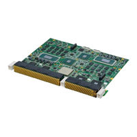
ADLINK Technology VPX6200 BIOS User Manual (113 pages)
VPX Dual Node Blade with Intel Xeon W-11865MRE
Brand:
ADLINK Technology
| Category:
Server
| Size: 5 MB
Table of Contents
Revision History
2
Preface
3
Table of Contents
5
List of Figures
7
List of Tables
9
Introduction
11
Overview
11
Features
11
Functional Block Diagrams
12
Figure 1-1: VPX6200 Functional Block Diagram
12
Figure 1-2: VPX6200-RL1 RTM Functional Block Diagram
13
Figure 1-3: VPX6200-RL2 RTM Functional Block Diagram
14
Model Number Decoder - Processor Blade
15
Package Contents
16
Rear Transition Module
16
Specifications
17
VPX6200 Blade Specifications
17
Table 2-1: VPX6200 Blade Specifications
17
VPX6200-RL1 RTM Specifications
21
Table 2-2: VPX6200-RL1 RTM Specifications
21
VPX6200-RL2 RTM Specifications
23
Table 2-3: VPX6200-RL2 RTM Specifications
23
Power Consumption
24
Table 2-4: VPX6200 Power Consumption
24
Board Interfaces
25
VPX6200 Board Layout
25
Figure 3-1: VPX6200 Board Layout - Top View
25
Figure 3-2: VPX6200 Board Layout - Bottom View
26
Figure 3-3: VPX6200 Status Leds - Front Side
27
Table 3-1: VPX6200 Status Leds - Front Side
27
Figure 3-4: VPX6200 Status Leds - Top Side
29
Table 3-2: VPX6200 Status Leds - Top Side
29
VPX6200 Front Panel Leds
30
Figure 3-5: VPX6200 Front Panel Leds - Front Side
30
Figure 3-6: VPX6200 System on Status LED
30
Table 3-3: VPX6200 System on Status LED
30
Figure 3-7: VPX6200 Storage Status LED
31
Figure 3-8: VPX6200 EC Status LED
31
Table 3-4: VPX6200 Storage Status LED
31
Table 3-5: VPX6200 EC Status LED
31
Table 3-6: EC Status LED Indication
31
Figure 3-9: VPX6200 Port 80H Status LED
33
Table 3-7: VPX6200 Port 80H Status LED
33
Figure 3-10: VPX6200 IPMC WDT LED
34
Table 3-8: VPX6200 IPMC WDT LED
34
VPX6200-RL1 RTM Board Layout
35
Figure 3-11: VPX6200-RL1 RTM Board Layout - Top View
35
Figure 3-12: VPX6200-RL1 RTM Board Layout - Bottom View
35
Figure 3-13: VPX6200-RL1 RTM Board Layout - Front View
36
Figure 3-14: VPX6200-RL1 Status Leds
36
Table 3-9: VPX6200-RL1 Status Leds
36
VPX6200-RL1 RTM Board Layout
37
Figure 3-15: VPX6200-RL1 RTM Board Layout - Top View
37
Figure 3-16: VPX6200-RL1 RTM Board Layout - Bottom View
37
Figure 3-17: VPX6200-RL1 RTM Board Layout - Front View
38
Figure 3-18: VPX6200-RL1 Status Leds
38
Table 3-10: VPX6200-RL1 Status Leds
38
VPX6200-RL2 RTM Board Layout
39
Figure 3-19: VPX6200-RL2 RTM Board Layout - Top View
39
Figure 3-20: VPX6200-RL2 RTM Board Layout - Front View
39
Figure 3-21: VPX6200-RL2 Status Leds
40
Table 3-11: VPX6200-RL2 Status Leds
40
VPX6200 Onboard Connector Pin Assignments
42
VPX6200 VPX Connector Pin Assignments
45
P2 Connector Pin Assignment
56
VPX6200-RL1 RTM Onboard Connector Pin Assignments
88
HDMI Connector
88
USB 3.0 Connector
88
IPMB Connector
91
VPX6200-RL1 RTM VPX Connector Pin Assignments
94
VPX6200-RL1 RTM Switches
100
Gigabit Ethernet Connectors
102
VPX6200-RL2 Onboard Connectors
102
Getting Started
103
Installing the VPX6200 to the Chassis
103
Installing the VPX6200-RL1 to the Chassis
103
Driver Installation
104
IPMC Firmware Update
105
EC Firmware Update
106
Utilities
109
Sema
109
Watchdog Timer
109
Important Safety Instructions
111
Getting Service
113
Advertisement
ADLINK Technology VPX6200 BIOS User Manual (76 pages)
Brand:
ADLINK Technology
| Category:
Computer Hardware
| Size: 1 MB
Table of Contents
Preface
2
Table of Contents
3
BIOS Setup Menu
5
Introduction
5
Menu Selection Bar
5
Menu Conventions
5
Getting Started
6
BIOS Information
7
System Information
7
System Date/Time
8
Board Information
8
Advanced Menu
10
CPU Configuration
11
Power & Performance
12
CPU - Power Management Control
12
GT - Power Management Control
23
Power Management
24
Voltage Monitor
25
System Management
26
SEMA Flags
27
Thermal Management
28
CPU Thermal Configuration
29
Platform Thermal Configuration
30
Temperatures
33
Watchdog Timer
34
Super IO Configuration
35
NCT5104DSEC Super IO Configuration
35
VPX Configuration
37
USB Configuration
39
AMI Graphic Output Protocol Policy
40
Serial Port Console Redirection
41
Network Stack Configuration
42
Trusted Computing
43
Chipset Menu
45
System Agent (SA) Configuration
46
Memory Configuration
47
PEG Port Feature Configuration
48
VMD Setup Menu
48
PCI Express Configuration
49
PCH-IO Configuration
52
SATA and RST Configuration
54
Software Feature Mask Configuration
56
USB Configuration
57
Security Configuration
58
HD Audio Configuration
59
Serial IO Configuration
60
PCH Thermal Throttling Control
61
Server Mgmt Menu
62
System Event Log
63
View FRU Information
64
BMC Network Configuration
65
ADLINK IPMI Configuration
66
View System Event Log
67
BMC User Settings
67
Security Menu
68
Secure Boot
70
Boot Menu
71
Save & Exit
73
Save and Exit
73
Important Safety Instructions
74
Getting Service
76
Advertisement
Related Products
ADLINK Technology VPX3010 Series
ADLINK Technology VPX3000 Series
ADLINK Technology VPX3001 Series
ADLINK Technology VPX3-TL Series
ADLINK Technology VPX3020 Series
ADLINK Technology VPX3020 RTM
ADLINK Technology VPX3-MXM/RTX5000
ADLINK Technology VPX6000 Series
ADLINK Technology VPX-R6000 RTM
ADLINK Technology 10GbE BASE-T
ADLINK Technology Categories
Computer Hardware
Motherboard
PCI Card
Control Unit
Desktop
More ADLINK Technology Manuals
Login
Sign In
OR
Sign in with Facebook
Sign in with Google
Upload manual
Upload from disk
Upload from URL