Sign In
Upload
Manuals
Brands
ADLINK Technology Manuals
Control Unit
USB-1901
User Manuals: ADLINK Technology USB-1901 DAQ Devices
Manuals and User Guides for ADLINK Technology USB-1901 DAQ Devices. We have
2
ADLINK Technology USB-1901 DAQ Devices manuals available for free PDF download: User Manual, Quick Start Manual
ADLINK Technology USB-1901 User Manual (84 pages)
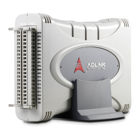
USB-1900 Series 16-bit 250kS/s USB 2.0-based High-performance DAQ Module
Brand:
ADLINK Technology
| Category:
Control Unit
| Size: 1 MB
Table of Contents
Revision History
2
Preface
3
Table of Contents
7
List of Figures
11
1 Introduction
15
Overview
15
Features
15
Applications
16
Specifications
17
General Specifications
17
Analog Input
18
Analog Output
21
Unpacking Checklist
22
Software Support
22
Driver Support for Windows
22
Utilities for Windows
23
2 Hardware Information
25
Overview and Dimensions
25
Module
25
Figure 2-1: USB-1902 Module Rear View
25
Figure 2-2: USB-1902 Module Side View
26
Figure 2-3: USB-1902 Module Front View
27
Module Stand
28
Figure 2-4: Module, Stand, Connector, and USB Cable
28
Figure 2-5: Module, Stand, & Wall Mount Kit Side View (W/ Connections)
28
Figure 2-6: Module in Stand Front View
29
Figure 2-7: Module Stand Top View
30
Figure 2-8: Module Stand Side Cutaway View
31
Figure 2-9: Module Stand Front View
31
Rail Mounting
32
Figure 2-10: Rail Mount Kit
32
Figure 2-11: Module Pre-Rail Mounting
32
Figure 2-12: Module Rail-Mounted
33
Wall Mounting
34
Figure 2-13: Wall Mount Holes
34
Figure 2-14: Module with Wall Mount Apparatus
34
Connector Pin Assignment
35
Table 2-1: USB-1901/1902 Pin Assignment in Single-End AI Mode
35
Table 2-2: USB-1901/1902 Pin Assignment in Pseudo-Differential AI Mode
36
Table 2-3: USB-1903 Pin Assignment
37
Connector Signal Description
38
Analog Input Signal Connection
38
Table 2-4: CN1/CN2 I/O Signal Description
38
Figure 2-15: Floating Source W/ RSE Input Connections
40
Figure 2-16: GRND-Referenced Sources W/ NRSE Inputs
41
Figure 2-17: GRND-Referenced Source W/ P-D Input
41
Figure 2-18: Floating Source W/ P-D Input
42
Figure 2-19: Current Input
43
3 Installing the USB-1900 Series Module
45
Connecting the USB-1900 Series Module
45
Figure 3-1: USB-1900 Module in Windows Device Manager
45
Device ID
46
Figure 3-2: Device ID Selection Control
46
Hardware Configuration
47
4 Operation
49
Signal Function
49
A/D Conversion
50
Figure 4-1: Functional Block Diagram (USB-1902)
50
AI Data Format
51
Analog Input Circuitry
51
Figure 4-2: Analog Input
51
Table 4-1: Bipolar Analog Input Range and Output Digital Code
51
Continuous Acquisition (Scanning) Mode
52
Software Conversion with Polling Data Transfer Acquisition Mode (Software Polling)
52
Figure 4-3: Analog Input Scan Timing
53
Analog Input Triggering
55
Trigger Sources
55
Software Triggering
55
External Analog Triggering
56
Figure 4-4: Below-Low Analog Triggering
56
External Digital Triggering
57
Trigger Modes
57
Figure 4-5: Above-High Analog Triggering
57
Figure 4-6: Digital Triggering
57
Delayed-Trigger Acquisition Mode (no Retriggering)
58
Figure 4-7: Post Trigger Without Retriggering
58
Post-Trigger Acquisition Mode (no Retriggering)
58
Figure 4-8: Delayed Trigger
59
Figure 4-9: Post Trigger or Delay Trigger with Retriggering
60
Gated Trigger
60
D/A Conversion
61
Figure 4-10: Gated Trigger
61
Bipolar Output Modes
62
Software Update
62
Table 4-2: Bipolar Output Code
62
Waveform Generation
62
Figure 4-11: Waveform Generation for Two Channel Update
63
Figure 4-12: FIFO Data In/Out Structure
63
Table 4-3: Waveform Generation Timer Definition
64
Figure 4-13: Waveform Generation Hardware Timing
65
Waveform Trigger Sources
65
Figure 4-14: Post-Trigger Waveform Generation
66
Waveform Generation Trigger Modes
66
Figure 4-15: Delayed-Trigger Waveform Generation
67
Figure 4-16: Post-Trigger or Delayed-Trigger with Retriggering
68
Figure 4-17: Infinite Iteration Waveform Generation
69
Programmable Function I/O
70
Ttl DI/Do
70
Table 4-4: Pin Definition of TTL Digital I/O
70
General Purpose Timer/Counter
71
Basic Timer/Counter Function
71
Table 4-5: Timer/Counter Pin Definition
71
General Purpose Timer/Counter Modes
72
Mode 1: Simple Gated-Event Counting
72
Figure 4-18: Mode 1-Simple Gated-Event Calculation
72
Mode 2: Single Period Measurement
73
Mode 3: Single Pulse-Width Measurement
73
Figure 4-19: Mode 2-Single Period Measurement
73
Mode 4: Single-Gated Pulse Generation
74
Mode 5: Single-Triggered Pulse
74
Figure 4-20: Mode 3-Single Pulse-Width Measurement
74
Figure 4-21: Mode 4-Single-Gated Pulse
74
Mode 6: Re-Triggered Single Pulse Generation
75
Figure 4-22: Mode 5-Single-Triggered Pulse
75
Figure 4-23: Mode 6-Re-Triggered Single Pulse
75
Mode 7: Single-Triggered Continuous Pulse Generation
76
Mode 8: Continuous Gated Pulse Generation
76
Mode 9: Edge Separation Measurement
76
Figure 4-24: Mode 7-Single-Triggered Continuous Pulse
76
Figure 4-25: Mode 8-Continuous Gated Pulse
76
Mode 10: PWM Output
77
Figure 4-26: Mode 9-Edge Separation Measurement
77
Figure 4-27: Mode 10-PWM Output
77
5 Calibration
79
Loading Calibration Constants
79
Auto-Calibration (USB-1901/1902 Only)
79
Saving Calibration Constants
80
Important Safety Instructions
81
Getting Service
83
Advertisement
ADLINK Technology USB-1901 Quick Start Manual (5 pages)
Brand:
ADLINK Technology
| Category:
Control Unit
| Size: 0 MB
Table of Contents
Abstract How to Use Pulse Measurement
1
Solution
2
Step 1: Identify Pins
2
Step 2: Connect Pins
3
Step 3: Install U-Test
3
Step 4: Launch Sample Program
4
Step 5: Set Gate and Clock
5
Step 6: Run
5
Advertisement
Related Products
ADLINK Technology USB-1210
ADLINK Technology USB-1902
ADLINK Technology USB-1903
ADLINK Technology USB-1900 Series
ADLINK Technology USB-2401
ADLINK Technology USBDAQ-9100MS
ADLINK Technology USB-3488A Series
ADLINK Technology USB-7230
ADLINK Technology USB-7250
ADLINK Technology ADM-TJ30
ADLINK Technology Categories
Computer Hardware
Motherboard
PCI Card
Control Unit
Desktop
More ADLINK Technology Manuals
Login
Sign In
OR
Sign in with Facebook
Sign in with Google
Upload manual
Upload from disk
Upload from URL