Sign In
Upload
Manuals
Brands
ADLINK Technology Manuals
Single board computers
cPCI-3600 Series
ADLINK Technology cPCI-3600 Series Manuals
Manuals and User Guides for ADLINK Technology cPCI-3600 Series. We have
1
ADLINK Technology cPCI-3600 Series manual available for free PDF download: User Manual
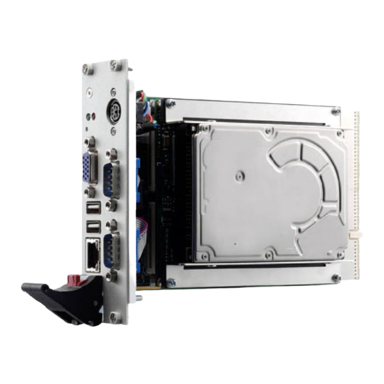
ADLINK Technology cPCI-3600 Series User Manual (70 pages)
3U CompactPCI Processor Blade with AMD Geode LX 800 @ 0.9W
Brand:
ADLINK Technology
| Category:
Single board computers
| Size: 2 MB
Table of Contents
Revision History
2
Preface
3
Table of Contents
9
Table of Contents
10
List of Figures
11
List of Tables
13
1 Introduction
15
Overview
15
Package Contents
16
Specifications
17
Features
20
Applications
20
2 Hardware Information
21
Functional Block Diagram
21
Figure 2-1: Cpci-3600 Series Block Diagram
21
Cpci-3600 CPU (ETX Module) Layout
22
Figure 2-2: ETX Module Layout Top View
22
Table 2-1: ETX Module Layout Top View Description
22
Figure 2-3: ETX Module Layout Soldered Side
23
Table 2-2: ETX Module Layout Soldered Side Description
23
Pin-Out Compatibility
24
Table 2-3: X1 Connector: PCI-Bus, USB, & Audio
24
Table 2-4: X2 Connector: ISA Bus
25
Table 2-5: X3 Connector: CRT, LCD (LVDS), & Video
26
Table 2-6: X3 Connector: COM 1/2, LPT1 or FDD, Irda, Mouse, & Keyboard
27
Cpci-3600 Series SBC & RTM Connectivity
29
Table 2-8: SBC & RTM Connectivity
29
Table 2-9: PCI Interrupt Connections
30
Cpci-3600 SBC (Carrier) Board Layout
31
Figure 2-4: Carrier Connector Layout
31
Table 2-10: Carrier Board Connectors & Jumpers
32
Cpci-3600 SBC (Carrier) Connectors & Jumpers on Board
33
Table 2-11: CN3: Compactflash Type I/II
33
Table 2-12: CN4: 44-Pin IDE
34
Table 2-13: J1: Compactpci® Pin Assignments
35
Table 2-14: J2: Compactpci® Pin Assignments
36
Table 2-15: JP1: CMOS Selection
37
Table 2-16: JP2: CF Mode Selection
37
Table 2-17: JPY1: VGA Selection
37
Cpci-3600 SBC (Carrier) Face-Plate Layout
38
Cpci-3600 SBC (Carrier) Connectors on Face-Plate
38
Figure 2-5: Carrier Face-Plate Layout
38
Table 2-18: COM 1 & COM 2 (CN6 & CNX1)
38
Table 2-19: LAN: RJ-45 Connector (CN8)
39
Table 2-20: LED Definition
39
Table 2-21: PS/2, KB/MS (CN1 Connector)
39
Table 2-22: USB 2.0 (CN5 & CN7 Right Angle Connector)
40
Table 2-23: VGA/CRT (CN2 Connector)
40
Cpci-3600 RTM Board Layout
41
Figure 2-6: RTM Connector Layout
41
Table 2-24: RTM Board Connectors & Jumpers
42
Cpci-3600 RTM Connectors & Jumpers on Board
43
Table 2-25: CN5: FDD Connector
43
Table 2-26: CN7: LPT Connector
44
Table 2-27: JP1: FDD/LPT Selection
44
Cpci-3600 RTM Face-Plate Layout
45
Figure 2-7: RTM Face-Plate Layout
45
Cpci-3600 RTM Connectors on Face-Plate
46
Table 2-28: Audio Port (PH 1 & PH 2 Connector)
46
3 BIOS Settings
47
Description
47
Main Menu Setup Items
48
Standard CMOS Features
49
Advanced BIOS Features
54
Advanced Chipset Features
57
Integrated Peripherals
59
Power Management Setup
62
Pnp/Pci Configurations
64
PC Health Status
66
Important Safety Instructions
67
Warranty Policy
69
Advertisement
Advertisement
Related Products
ADLINK Technology cPCI-3600 SBC
ADLINK Technology cPCI-3600 CPU
ADLINK Technology cPCI-6880 Series
ADLINK Technology cPCI-R6000 Series
ADLINK Technology cPCI-R6000D Series
ADLINK Technology cPCI-R6100
ADLINK Technology cPCI-R6101
ADLINK Technology cPCI-6910VS/M2G-GP
ADLINK Technology cPCI-6842 Series
ADLINK Technology cPCI-6842-2
ADLINK Technology Categories
Computer Hardware
Motherboard
PCI Card
Control Unit
Desktop
More ADLINK Technology Manuals
Login
Sign In
OR
Sign in with Facebook
Sign in with Google
Upload manual
Upload from disk
Upload from URL