Sign In
Upload
Manuals
Brands
Ademco Manuals
Security System
VISTA-250BP
Ademco VISTA-250BP Manuals
Manuals and User Guides for Ademco VISTA-250BP. We have
2
Ademco VISTA-250BP manuals available for free PDF download: Installation And Setup Manual, Programming Manual
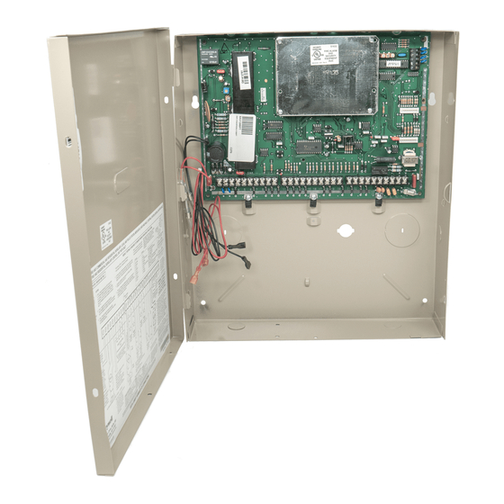
Ademco VISTA-250BP Installation And Setup Manual (128 pages)
Brand:
Ademco
| Category:
Security System
| Size: 1.15 MB
Table of Contents
Table of Contents
3
List of Figures
5
Conventions Used in this Manual
6
SECTION 1: General Description
7
About the VISTA-128BP/VISTA-250BP
7
Features
7
SECTION 2: Partitioning and Panel Linking
11
Theory of Partitioning
11
Setting-Up a Partitioned System
11
Common Lobby Logic
11
Master Keypad Setup and Operation
13
Panel Linking
14
How to Use Panel Linking
15
SECTION 3: Installing the Control
19
Mounting the Control Cabinet
19
Installing the Cabinet Lock
19
Grade a Mercantile Premises Listing Guidelines
19
Grade a Mercantile Safe and Vault Listing Guidelines
20
Installing the Control's Circuit Board
20
Figure 3-2: Cabinet Attack Resistance Considerations
20
Figure 3-3: Mounting the PC Board
20
Installing the Keypads
21
Figure 3-4: Keypad Connections to Control Panel
21
Figure 3-5: Using a Supplementary Power Supply
21
Installing External Sounders
22
Figure 3-6: Wiring Polarized Fire Devices
22
Telephone Line Connections
23
Figure 3-7: Wiring Nonpolarized Burglary Devices
23
Figure 3-8: Telephone Line Connections
23
Wiring Burglary and Panic Devices to Zones 1-9
24
Figure 3-11: 4-Wire Smoke Detectors
25
Figure 3-12A: Wiring a 333PRM to the Control
25
Figure 3-12B: Wiring a 333PRM Using a 4204
25
Figure 3-12C: Wiring a 333PRM Using a 4204 and a Power Supply
25
Figure 3-14: Wiring a Normally Closed Loop for Tamper Supervision
26
Figure 3-15: Wiring a Normally Open Loop for Tamper Supervision
26
Figure 3-13: Wiring Latching Glassbreaks to Zone 8
26
Installing RPM Devices
27
Wireless Zone Expansion
28
Figure 3-16: Polling Loop Connections to the VISTA-128BP/VISTA-250BP
28
Figure 3-17: Polling Loop Connections Using One 4297 Extender Module
28
Figure 3-18: Polling Loop Connections Using Multiple Extender Modules
28
Figure 3-19: Installing the 5881ENHC with Tamper Protection
29
Figure 3-20: 5881 RF Receiver (Cover Removed)
30
Installing Output Devices
32
Figure 3-21: 4204 Relay Module
32
Figure 3-22: 4204CF Relay Module
32
Installing the Ground Start Module
33
Figure 3-23: Wiring the FSA Module
33
Installing a Remote Keyswitch
34
Figure 3-24: Ground Start Module Connections
34
Figure 3-25: Remote Keyswitch Wiring
34
Smoke Detector Reset
35
Remote Keypad Sounder
35
Installing the VA8200 Panel Link Module
35
Figure 3-26: Remote Keypad Sounder Wiring
35
Figure 3-27: Panel Linking Block Diagram
35
Long Range Radio Connected to the J7 Triggers
36
Figure 3-28: VA8200 Panel Link Module Wiring
36
Long Range Radio Connected to the ECP
37
Figure 3-29: Wiring Long Range Radio to Keypad Terminals
37
Installing the Alpha Pager Module
38
Figure 3-30: Wiring the Alpha Pager Module
39
Access Control Using Vistakey
40
Access Control Using the Passpoint Access Control System
41
Event Log Connections
41
Figure 3-31: Wiring the Vistakey
41
Figure 3-32: Wiring the VISTA Gateway Module
41
Installing the 4285/4286 VIP Module
42
Figure 3-33: Printer Connections to the 4100SM
42
Installing the Audio Alarm Verification Module
43
Figure 3-34: 4285/4286 VIP Module Connections
43
Installing Telesmart
44
Figure 3-35: AAV Connections to J7 Trigger
44
Figure 3-36: AAV Connections to 4204 Relay Module
44
Figure 3-37: AAV and 4286 VIP Module Connections to the J7 Trigger
44
Figure 3-38: Telesmart Phone Connections
45
Figure 3-39: Telesmart Speaker Connection
45
Figure 3-40: Keypad Connections
45
Connecting the Transformer
46
Figure 3-41: RTC and Ground Connections
46
Figure 3-42: Telesmart to Control Connections
46
Figure 3-43: 1321 Transformer and Battery Connections
46
Figure 3-44: 4300 Transformer Connections
46
Panel Earth Ground Connections
47
Determining the Control's Power Supply Load
47
Determining the Size of the Standby Battery
48
SECTION 4: Programming
51
Program Modes
51
Entering and Exiting Programming Mode
51
Data Field Programming Mode
51
#93 Menu Mode Programming
52
Zone Number Designations
54
Zone Response Type Definitions
56
Zone Input Type Definitions
57
Programming for Panel Linking
58
Programming for the Alpha Pager Module
59
Programming for Telesmart
59
Programming for Access Control
59
Programming for ECP Long Range Radio
60
Programming for the Event Log
60
SECTION 5: Data Field Descriptions
61
About Data Field Programming
61
Programming Data Fields
61
SECTION 6: Scheduling Options
79
Time Window Definitions
80
Open/Close Schedules Definitions
81
Scheduling Menu Mode
82
Time Windows
83
Daily Open/Close Schedules
84
Holiday Schedules
84
Time-Driven Events
85
Limitation of Access Schedules
89
Temporary Schedules
90
User Scheduling Menu Mode
92
SECTION 7: Downloading Primer
93
General Information
93
Unattended Download
93
Getting On-Line with a Control Panel
95
Scheduled Download
96
Direct-Wire Downloading
96
Telco Handoff
96
Figure 7-1: Direct-Wire Downloading Connections
96
SECTION 8: Setting the Real-Time Clock
97
General Information
97
Setting the Time and Date
97
SECTION 9: User Access Codes
99
General Information
99
User Codes & Levels of Authority
99
Multiple Partition Access
100
Adding a Master, Manager, or Operator Code
101
Changing a Master, Manager, or Operator Code
102
Adding an RF Key to an Existing User
102
Deleting a Master, Manager, or Operator Code
102
Exiting the User Edit Mode
102
SECTION 10: Testing the System
103
Battery Test
103
Dialer Test
103
Burglary Walk-Test (Code + [5] TEST)
103
Armed Burglary System Test
103
Testing Wireless Transmitters
104
Trouble Conditions
105
To the Installer
105
APPENDIX A: Regulatory Agency Statements
107
UL Installation Requirements
107
UL609 Grade a Local Mercantile Premises/Local Mercantile Safe & Vault
107
UL365 Police Station Connected Burglar Alarm
107
UL611/UL1610 Central Station Burglary Alarm
108
California State Fire Marshal (CSFM) and UL Residential Fire Battery Backup Requirements
108
APPENDIX B: Summary of System Commands
111
APPENDIX C: Specifications
113
APPENDIX D: Contact ID and Pager Event Codes
115
Table of Contact ID Event Codes
115
Event Log and Pager Alpha Descriptors
116
Index
119
Appendix E
124
Appendix E
124
The Limitations of this Alarm System
124
Ademco Limited Warranty
125
Summary of Connections
126
Advertisement
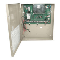
ADEMCO VISTA-250BP Programming Manual (72 pages)
Commercial Burglary Partitioned Security System with Scheduling
Brand:
ADEMCO
| Category:
Security System
| Size: 4.41 MB
Table of Contents
Table of Contents
2
5Hfrpphqghg 3Urjudpplqj 3Urfhgxuh
3
3Urjudp )Lhog ,Qgh
4
9,67$%39,67$%3 3Urjudpplqj )Rup
5
3Duwlwlrq6Shflilf )Lhogv
12
3Urjudpplqj :Lwk 0Hqx 0Rgh
14
=Rqh3Urjudpplqj
15
6Hulhv7Udqvplwwhuv/Rrs'Hvljqdwlrqv
19
5Hsruw &Rgh 3Urjudpplqj
24
Oskd 'Hvfulswruv 3Urjudpplqj
27
Oskd 'Hvfulswru 9Rfdexodu
31
Hylfh 3Urjudpplqj
32
2Xwsxw 3Urjudpplqj
35
5Hod\ 9Rlfh 'Hvfulswruv
39
5Hod\ 9Rlfh 'Hvfulswruv Dqg &Xvwrp :Rug 6Xevwlwxwhv 9Rfdexodu
40
Xvwrp :Rug 6Xevwlwxwhv Iru 9,3 0Rgxoh $Qqxqfldwlrq
40
6Fkhgxohg &KhfnLq
41
Vwhp /D\Rxw :Runvkhhwv
42
2Xwsxw 'Hylfhv :Runvkhhwv
58
6Fkhgxolqj 0Hqx 3Urpswv
64
6Fkhgxolqj :Runvkhhwv
65
Advertisement
Related Products
ADEMCO VISTA-250FBP
ADEMCO VISTA-25
Ademco VISTA-20HWse
ADEMCO VISTA-20P Series
ADEMCO VISTA-20PS
Ademco Vista-20
ADEMCO Vista-20HW
ADEMCO VISTA-20PCN
ADEMCO VISTA-20SEA
ADEMCO Vista-2000
Ademco Categories
Security System
Security Sensors
Keypad
Transmitter
Smoke Alarm
More Ademco Manuals
Login
Sign In
OR
Sign in with Facebook
Sign in with Google
Upload manual
Upload from disk
Upload from URL