Sign In
Upload
Manuals
Brands
ADCMT Manuals
Monitor
6241A
ADCMT 6241A Manuals
Manuals and User Guides for ADCMT 6241A. We have
1
ADCMT 6241A manual available for free PDF download: Operation Manual
ADCMT 6241A Operation Manual (306 pages)
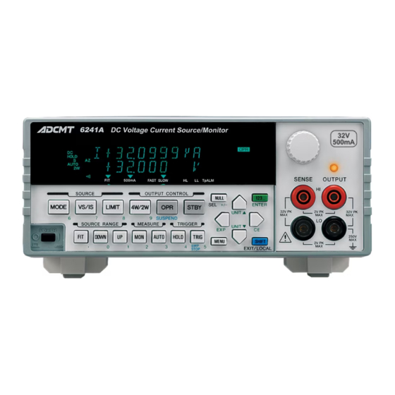
DC Voltage Current Source/Monitor
Brand:
ADCMT
| Category:
Monitor
| Size: 3 MB
Table of Contents
Table of Contents
11
1 Preface
21
Product Overview
21
Supplied Accessories
22
Standard Accessory List
22
Optional Accessories
23
Optional Accessory List
23
Operating Environment
24
Environmental Conditions
24
Operating Environment
25
Power Specification
26
Set Power Voltage Indicator
26
Power Supply Specification
26
Changing Power Voltage, and Checking and Replacing Power Fuse
27
Power Cable
28
Operating Check
29
Connecting the Power Cable
29
Screen Displaying Self-Test
29
Screen Displaying Self-Test Completion
30
Start-Up Screen
30
VSVM Measurement (in Output off Standby)
30
Displaying VSVM 300 MV Range, 0 V Measurement
31
Cleaning, Storage, and Transport Methods
32
Cleaning
32
Storage
32
Transport
32
Warm-Up Time
33
Calibration
33
Life Limited Parts
33
1.10 Product Disposal and Recycling
34
2 Operation
37
Panel Descriptions
37
Front Panel
38
Display Section
39
SOURCE Section
39
SOURCE RANGE Section
40
MEASURE Section
40
OUTPUT CONTROL Section
41
TRIGGER Section
41
Other Keys
42
Output Section
43
POWER Switch
43
Screen Display (Annotations)
44
Basic Operation
49
Setting Source Value
49
Relation between Keys
49
Setting Source Value Using Cursor Keys/Rotary Knob
50
Setting Source Value Using Cursor Keys/Rotary Knob
54
Setting Source Value Using Direct Input Mode
55
2.2.2 Setting Limiter Value
57
2.2.3 Menu Operation
61
Method of Menu Operation
61
Menu Operation Overview
62
Keys and Menu Functions
63
Menu Structure and Parameter Setting
64
Initializing Setting Conditions
70
DC Measurement
71
2.2.6 Pulse Measurement
75
Sweep Measurement
79
Saving and Loading Parameters
84
Auto Load at Power on
84
Saving Parameters
84
2.3.3 Loading Parameters
85
3 Measurement Example
87
3.1 Measurement of Diode
88
Diode Measurement Connection
88
Battery Charge and Discharge Test
89
Waveform of Battery Discharging Test
90
Battery Charge Discharge Test Connection
91
Menu Index
93
Function Description
95
AUTO Key (Measurement Range)
95
DOWN Key (Source Range)
95
FIT Key (Source Range)
95
HOLD Key (Trigger Mode)
96
LIMIT Key (Limiter Setting)
96
MENU Key (Parameter Setting)
96
Linear Sweep
98
Fixed Sweep
98
Two Slope Linear Sweep
99
STBY in
103
Interlock in
103
OPR/STBY in
104
MODE Key (Source Mode)
107
MON Key (Measurement Mode)
107
NULL/SEL Key
107
OPR/SUSPEND (Operating/Suspend)
108
SHIFT/LOCAL (Shift Mode/Local)
108
STBY Key (Output Standby)
109
TRIG/SWP STOP (Trigger/Sweep Stop)
109
UP Key (Increasing the Source Range)
109
VS/IS Key (Source Function)
110
Key (Direct Input Mode)
110
2W Key (Remote Sensing Selection)
110
5 Technical References
111
DUT Connection
111
Note for Output Terminals
111
Internal Wire Connection
111
Remote Sensing (2-Wire or 4-Wire Connection)
112
Preventing Oscillation
114
Preventing 6241A/6242 Oscillation
114
Reducing Stray Capacitance and Lead Inductor
114
Oscillation from the Device Itself
115
Preventing Device Oscillation
115
6241A/6242 Oscillation Countermeasures
115
Connection for High Current Measurement
116
Tolerable Current and Wire Thickness
116
Connecting with the Fixture 12701A
117
Connection with the 12701A
117
Functions in Detail
118
DC Source Mode Operation
118
5.2.2 Pulse Source Mode Operation
120
Sweep Source Mode Operation
122
DC Sweep Source Mode Operation
125
DC Sweep Source Mode
125
Pulse Sweep Source Mode Operation
127
Random Sweep and Random Pulse Sweep
128
Two Slope Linear Sweep
129
Two Slope Linear Pulse Sweep
129
Reverse Function
130
Reverse Operation at DC Sweep
130
RTB Function
131
Reverse Operation at Pulse Sweep
131
5.2.4 Source Function
132
Source Mode, Source Function, and Setting Parameters
132
Restrictions on Changing Source Function
133
Source Range
133
Suspend Function
135
Concept of Output Status
135
Measurement Function
138
Measurement Ranging
139
Measurement Delay Time and Measurement Value
144
Measuring in Sample Hold Mode
145
Auto Zero Function
146
Switching Unit Display
147
Relation between Prefix of the Unit and Digit
147
Limiter (Compliance)
148
Limiter Setting Ranges
148
Setting the Limiter
149
Rechargeable Battery Charge and Discharge Operations
149
Displaying and Outputting of Limiter Detection
150
Alarm Detection
150
Alarm Detection Contents
150
Source Timing and Measurement Timing
151
Source Mode and Time Parameters to be Considered
151
Restriction on Time Parameter
152
Measurement Delay and Settling Time
154
Integration Time and Measurement Time
157
Auto Range Delay
157
5.2.9 Calculation Functions
159
NULL Calculation
159
NULL Calculation Timing
159
Scaling Calculation
160
Comparator Calculation
161
Max/Min Calculation
162
External Control Signals
163
External Control Signal Functions
163
Restrictions on Using External Trigger
164
Restrictions on Tp, Tp (Ext), Th, and Th (Ext)
164
TA Value
165
Restriction on Top
165
Control of Scanner
167
Operating Multiple 6241A/6242
168
Synchronized Operation
168
Operate out
168
OPR/SUS in
168
Serial Connection
171
Parallel Connection
172
Measurement Data Storing Function
173
Storing Measured Data into Data Memory (Memory Store)
173
Conceptual Diagram of Storing Measured Data
173
Clearing Saved Data (Memory Clear)
174
Comparison of Storing Measured Data
174
5.2.14 Error Log
175
5.2.15 Self Test
176
Self-Test Items
176
Self-Test Operation
178
Compatibility with 6243/44
179
Remote Command Compatibility
179
Difference of Period-Parameters in Pulse Source Mode and Sweep Source Mode
179
Notes for Synchronous Operation
180
Operational Principles
181
6 Remote Programming
183
Using an Interface
183
Selecting the Interface
183
6.2 Remote Command Index
184
Gpib
187
Overview
187
Interface Function
187
Precautions When Using GPIB
188
Standard Bus Cable
188
6.3.3 Setting GPIB
189
Usb
190
Overview
190
USB Specifications
190
USB Setup
190
Connection to PC
190
Precautions When Using USB
191
Status Register Structure
192
Structure of Status Register
193
Structure of Status Byte Register
194
Status Byte Register (STB)
195
Standard Event Status Register (ESR)
196
Device Event Status Register (DSR)
197
Error Register (ERR)
199
Data Output Format (Talker Format)
200
Remote Command
204
Command Syntax
204
Data Format
205
Remote Command List
206
TER? Command
222
Programming Example 2: Pulse Measurement
225
Programming Example 4: Using Measurement Buffer Memory
228
Programming Examples with USB
230
Programming Example: DC Measurement
230
7 Performance Test
233
6241A Tests
233
Measuring Instruments Required for Performance Tests
233
Connection
233
Test Methods
233
Measuring Instruments Required for Performance Tests
235
Connection
235
Test Methods
235
8 Calibration
239
6241A Calibration
239
Cables and Measuring Instruments Required for Calibration
239
Safety Precautions
240
Connections
240
Connections for 6241A Calibration
240
Calibration Points and Tolerance Range
241
Calibrating Operation
243
6241A Calibration Procedure
243
6241A Calibration Procedure
244
6241A Calibration Procedure
245
6241A Calibration Procedure
246
6241A Calibration Procedure
247
Calibration Procedure
248
Voltage-Source and Voltage-Limiter Calibration
248
Voltage-Measurement Calibration
249
Cables and Measuring Instruments Required for Calibration
251
Safety Precautions
252
Connections
253
Calibration Points and Tolerance Range
254
Calibrating Operation
256
Calibration Procedure
263
Voltage-Source and Voltage-Limiter Calibration
263
Voltage-Measurement Calibration
264
Current-Source and Current-Limiter Calibration (30 Μa to 300 Ma)
264
Current-Source and Current-Limiter Calibration, (3 A, 5 A)
265
Current-Measurement Calibration (30 Μa to 300 Ma)
266
Current-Measurement Calibration (3 A, 5 A)
266
9 Specifications
267
Source and Measurement
274
9.1.2 6242 Source and Measurement
275
Source and Measurement Function
282
Set Time
283
General Specification
285
Appendix
287
When Problems Occur (before Requesting Repairs
287
Items to be Inspected before Requesting the Repair
287
A.2 Error Message List
289
A.3 Execution Time
293
GPIB/USB Remote Execution Time (Typical Value
293
Internal Processing Time (Typical Value
297
Dimensional Outline Drawing
299
Alphabetical Index
301
Advertisement
Advertisement
Related Products
ADCMT 6242
ADCMT 6253
ADCMT 6240B
ADCMT 6247G
ADCMT 6247C
ADCMT 6243
ADCMT 6244
ADCMT 6166
ADCMT 6146
ADCMT 6156
ADCMT Categories
Measuring Instruments
Multimeter
Monitor
Portable Generator
Accessories
More ADCMT Manuals
Login
Sign In
OR
Sign in with Facebook
Sign in with Google
Upload manual
Upload from disk
Upload from URL