
Subscribe to Our Youtube Channel
Related Manuals for ADCMT 6241A

Summary of Contents for ADCMT 6241A
- Page 1 Cover 6241A/6242 DC Voltage Current Source/Monitor Operation Manual FOE-00000029B00 MANUAL NUMBER Applicable Models 6241A 6242 First printing June1, 2008 ADC CORPORATION 2008 All rights reserved. Printed in Japan...
- Page 3 Safety Summary Safety Summary To ensure thorough understanding of all functions and to ensure efficient use of this instrument, please read the manual carefully before using. Note that ADC Corporation (hereafter referred to as ADC) bears absolutely no re- sponsibility for the result of operations caused due to incorrect or inappropriate use of this instrument. If the equipment is used in a manner not specified by ADC, the protection provided by the equipment may be im- paired.
- Page 4 Safety Summary product. • When the product has ventilation outlets, do not stick or drop metal or easily flammable ob- jects into the ventilation outlets. • When using the product on a cart, fix it with belts to avoid its drop. •...
- Page 5 Safety Summary Main Parts with Limited Life Part name Life Unit power supply 5 years Fan motor 5 years Electrolytic capacitor 5 years LCD display 6 years LCD backlight 2.5 years Floppy disk drive 5 years Memory backup battery 5 years •...
- Page 6 Environmental Conditions This instrument should be only be used in an area which satisfies the following conditions: • An area free from corrosive gas • An area away from direct sunlight • A dust-free area • An area free from vibrations •...
- Page 7 Types of Power Cable Replace any references to the power cable type, according to the following table, with the appropriate power cable type for your country. Rating, color Model number Plug configuration Standards and length (Option number) PSE: Japan 125 V at 7 A Straight: A01402 Black...
- Page 9 Certificate of Conformity This is to certify, that DC Voltage Current Source/Monitor 6241A, 6242 instrument, type, designation complies with the provisions of the EMC Directive 2004/108/EC in accordance with EN61326 and Low Voltage Directive 2006/95/EC in accordance with EN61010. ADC Corp.
-
Page 11: Table Of Contents
TABLE OF CONTENTS 6241A/6242 DC Voltage Current Source/Monitor Operation Manual TABLE OF CONTENTS PREFACE ...................... Product Overview ....................Supplied Accessories ..................Optional Accessories ..................Operating Environment ..................1.4.1 Environmental Conditions ................1.4.2 Power Specification ..................1.4.3 Changing Power Voltage, and Checking and Replacing Power Fuse .. - Page 12 6241A/6242 DC Voltage Current Source/Monitor Operation Manual Table of Contents 2.2.5 DC Measurement ..................2-35 2.2.6 Pulse Measurement ..................2-39 2.2.7 Sweep Measurement ................... 2-43 Saving and Loading Parameters ................ 2-48 2.3.1 Auto Load at Power On ................2-48 2.3.2 Saving Parameters ..................
- Page 13 6241A/6242 DC Voltage Current Source/Monitor Operation Manual Table of Contents 5.2.3.3 Random Sweep and Random Pulse Sweep ..........5-18 5.2.3.4 Two Slope Linear Sweep ................5-19 5.2.3.5 Reverse Function ..................5-20 5.2.3.6 RTB Function ..................... 5-21 5.2.4 Source Function ..................
- Page 14 6241A/6242 DC Voltage Current Source/Monitor Operation Manual Table of Contents 5.4.2 Operational Principles ................5-71 REMOTE PROGRAMMING ..............Using an Interface ..................... 6.1.1 Selecting the Interface ................Remote Command Index ................... GPIB ........................6.3.1 Overview ....................6.3.2 Precautions when Using GPIB ..............
- Page 15 6241A/6242 DC Voltage Current Source/Monitor Operation Manual Table of Contents 8.1.3 Connections ....................8.1.4 Calibration Points and Tolerance Range ............ 8.1.5 Calibrating Operation ................. 8.1.5.1 Calibration Procedure ................. 8-10 8.1.5.2 Voltage-source and Voltage-limiter Calibration ........8-10 8.1.5.3 Voltage-measurement Calibration ..............
- Page 17 6241A/6242 DC Voltage Current Source/Monitor Operation Manual LIST OF ILLUSTRATIONS Title Page Operating Environment ..................... Set Power Voltage Indicator ..................... Power Cable ........................Connecting the Power Cable ..................... Screen Displaying Self-Test ..................... Screen Displaying Self-Test Completion ................. 1-10 Start-up Screen ........................
- Page 18 6241A/6242 DC Voltage Current Source/Monitor Operation Manual List of Illustrations Title Page Connection for High Current Measurement ..............Connection with the 12701A .................... Random Sweep and Random Pulse Sweep ............... 5-18 Two Slope Linear Sweep ....................5-19 5-10 Two Slope Linear Pulse Sweep ..................
- Page 19 6241A/6242 DC Voltage Current Source/Monitor Operation Manual LIST OF TABLES Title Page Standard Accessory List ....................Optional Accessory List ....................Power Supply Specification ....................Keys and Menu Functions ....................2-27 Tolerable Current and Wire Thickness ................DC Source Mode Operation .....................
-
Page 21: Preface
This manual describes the accessories, operating environment, precautions, and operating check for person- nel who operate the 6241A/6242. Read this manual before using the 6241A/6242. Product Overview The 6241A/6242 is a DC Voltage Current Source/Monitor with wide source/measurment ranges, as shown below. Voltage 0 to ±32 V, Current 0 to ±500 mA 6241A: Voltage 0 to ±6 V, Current 0 to ±5 A... -
Page 22: Supplied Accessories
6241A/6242 DC Voltage Current Source/Monitor Operation Manual 1.2 Supplied Accessories Supplied Accessories The 6241A/6242 standard accessories are listed below. If any accessory is missing or damaged, contact an ADC CORPORATION sales representative. Specify the part number when ordering. Table 1-1 Standard Accessory List... -
Page 23: Optional Accessories
6241A/6242 DC Voltage Current Source/Monitor Operation Manual 1.3 Optional Accessories Optional Accessories The 6241A/6242 optional accessories are listed below. Specify the part number when ordering. Table 1-2 Optional Accessory List Name Part number Remarks Test fixture 12701A Connecting cable A01041... -
Page 24: Operating Environment
Obstructing the vents will cause the internal temperature to rise, possibly causing faulty operation. • Mounting in a rack Ensure that exhaust air from other devices is not directed at the vents on the side of the 6241A/6242. To prevent the temperature in the rack from rising, install a heat sink fan. -
Page 25: Operating Environment
Figure 1-1 Operating Environment NOTE: Warm-up Time Allow the 6241A/6242 to warm up for at least 60 minutes after turning on the power to ensure the spec- ified accuracy of 6241A/6242. -
Page 26: Power Specification
1.4.2 Power Specification 1.4.2 Power Specification Table 1-3 below shows the 6241A/6242 power supply specifications. CAUTION: To prevent damage to the 6241A/6242, do not apply a voltage or frequency that exceeds the speci- fied range. Table 1-3 Power Supply Specification Optional Standard... -
Page 27: Changing Power Voltage, And Checking And Replacing Power Fuse
1.4.3 Changing Power Voltage, and Checking and Replacing Power Fuse 1.4.3 Changing Power Voltage, and Checking and Replacing Power Fuse The 6241A/6242 power voltage can be changed manually. This section describes the procedure for changing the power voltage, and checking and replacing the power fuse. -
Page 28: Power Cable
6241A/6242 DC Voltage Current Source/Monitor Operation Manual 1.4.4 Power Cable Return the fuse holder assembly into the rear panel. Verify that a rated fuse is installed and that the correct power voltage appears in the window. 1.4.4 Power Cable NOTE: Use a power cable that conforms to the power outlet voltage and type. -
Page 29: Operating Check
1.5 Operating Check Operating Check This section describes the simple self-test which must be performed when operating the 6241A/6242 for the first time. Follow the procedure below to ensure the 6241A/6242 operates correctly. Ensure that the POWER switch on the front panel is set to OFF. -
Page 30: Screen Displaying Self-Test Completion
6241A/6242 DC Voltage Current Source/Monitor Operation Manual 1.5 Operating Check Software revision Model name (6241A/6242) Figure 1-6 Screen Displaying Self-Test Completion Figure 1-7 Start-up Screen NOTE: Depending on the previous conditions, the screen display may be different from Figure 1-7. -
Page 31: Displaying Vsvm 300 Mv Range, 0 V Measurement
Verify that the VM measured value is within ±22 μV of 0 V in the VS 300 mV range. Press STBY. The OPR indicator goes OFF and the 6241A/6242 enters the standby (output OFF) mode. The operation check is complete. -
Page 32: Cleaning, Storage, And Transport Methods
(90 days or longer), place the 6241A/6242 in a moisture-proof bag together with a desiccant. Avoid storing the 6241A/6242 in a location where there is a lot of dust or where it will be sub- jected to direct sunlight. -
Page 33: Warm-Up Time
6241A/6242 DC Voltage Current Source/Monitor Operation Manual 1.7 Warm-up Time Warm-up Time Allow the 6241A/6242 to warm up for at least 60 minutes after turning on the power to ensure the specified accuracy of 6241A/6242. Calibration Calibrations are conducted by ADC. Contact an ADC CORPORATION sales representative for the calibra- tion service. -
Page 34: 1.10 Product Disposal And Recycling
1.10 Product Disposal and Recycling 1.10 Product Disposal and Recycling Correctly dispose of the 6241A/6242 in accordance with local and national regulations. Before disposal, remove the following parts from the product to prevent dispersal of substances that may adversely affect the environment, human health, or the ecosystem. - Page 35 6241A/6242 DC Voltage Current Source/Monitor Operation Manual 1.10 Product Disposal and Recycling Name of substance or removed part Used? Location Unit Part Nickel or its compounds Unit Electronic components, mechanical components Lead or its compounds Unit BPL-034287X02 Electronic components on...
-
Page 37: Operation
OPERATION This chapter describes the part names and functions on the front and rear panels and the screen display (anno- tation) elements. The operation procedure of the 6241A/6242 is explained in this chapter by using measure- ment examples. Panel Descriptions This section describes the part names and functions on the front and rear panels, and the screen display (anno- tation) elements. -
Page 38: Front Panel
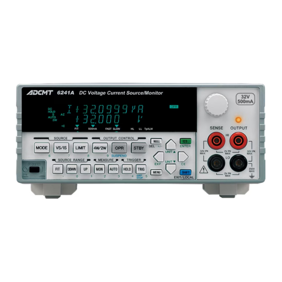
6241A/6242 DC Voltage Current Source/Monitor Operation Manual 2.1.1 Front Panel 2.1.1 Front Panel The following describes the panel keys and connectors for each front panel section. 6241A 6242 Figure 2-1 Front Panel... -
Page 39: Display Section
6241A/6242 DC Voltage Current Source/Monitor Operation Manual 2.1.1 Front Panel The front panel is divided into the following nine sections. Display Section SOURCE Section SOURCE RANGE Section MEASURE Section OUTPUT CONTROL Section TRIGGER Section Other Keys Output Section POWER Switch 2.1.1.1... -
Page 40: Source Range Section
6241A/6242 DC Voltage Current Source/Monitor Operation Manual 2.1.1 Front Panel 2.1.1.3 SOURCE RANGE Section Figure 2-4 SOURCE RANGE Section FIT key: Selects the optimum fitting range (FIT) or the current range to input the source values. DOWN key: Lowers the source range. -
Page 41: Output Control Section
6241A/6242 DC Voltage Current Source/Monitor Operation Manual 2.1.1 Front Panel 2.1.1.5 OUTPUT CONTROL Section 2, 3 Figure 2-6 OUTPUT CONTROL Section 4W/2W key: Selects the output sensing 4-wire or 2-wire connection. OPR key: Switches between Operate and Suspend. * :Suspend status outputs the suspended voltage without turning OFF the output relay. -
Page 42: Other Keys
6241A/6242 DC Voltage Current Source/Monitor Operation Manual 2.1.1 Front Panel 2.1.1.7 Other Keys 7, 8, 9 Figure 2-8 Other Keys MENU key: Displays a parameter group setting (menu) screen. NULL key: Sets the NULL calculation. 123... key: Switches to the direct input mode, sets the value, and executes the source generation on the setting screen which accepts the numer- ical input. -
Page 43: Output Section
6241A/6242 DC Voltage Current Source/Monitor Operation Manual 2.1.1 Front Panel 2.1.1.8 Output Section Figure 2-9 Output Section OUTPUT terminal: Voltage and current output terminal SENSE terminal: Functions as a sensing terminals for voltage output in the remote sense mode (4-wire connection) and input terminals for volt- age-measurement. -
Page 44: Screen Display (Annotations)
6241A/6242 DC Voltage Current Source/Monitor Operation Manual 2.1.2 Screen Display (Annotations) 2.1.2 Screen Display (Annotations) This section describes the screen display (annotations). 6241A 6242 Figure 2-11 Screen Display (Annotations) Source Value: Displays voltage source (VS) or current source (IS) value with a unit. - Page 45 6241A/6242 DC Voltage Current Source/Monitor Operation Manual 2.1.2 Screen Display (Annotations) Measurement function: Displays the measurement functions. current measurement (IM) voltage measurement (VM) resistance measurement (RM) Measurement OFF Left status Indicators: PLS: Source mode is in pulse mode. SWP: Source mode is in Sweep mode.
- Page 46 When the Comparator calculation is ON, either one of these three indicators illuminates depending on the results. LMT: Value is at limiter status. OSC: (Not in use) RVS: (Not in use) BUSY: (Not in use) SHIFT: The 6241A/6242 is in shift mode status. 2-10...
- Page 47 2.1.3 Rear Panel Figure 2-12 Rear Panel AC power connector Connects the 6241A/6242 to the AC power supply by using the supplied power cable. Voltage Selector and Fuse Holder Selects voltage manually to match the AC power supply. A fuse is contained inside.
- Page 48 6241A/6242 DC Voltage Current Source/Monitor Operation Manual 2.1.3 Rear Panel INTERLOCK | OPERATE IN/OUT INTERLOCK : Interlock signal is input. Input resistance is about 10 kΩ. OPERATE IN : Sets Standby with rising edge signal input when in STBY In function.
-
Page 49: Basic Operation
6241A/6242 DC Voltage Current Source/Monitor Operation Manual 2.2 Basic Operation Basic Operation This section describes the following items: • Setting Source Value • Setting Limiter Value • How to use the Menu and basic measurement functions. NOTE: The operation procedures listed permit the settings to be made in the shortest time. If the display differs from the one shown, repeat the procedure from the beginning. -
Page 50: Setting Source Value Using Cursor Keys/Rotary Knob
6241A/6242 DC Voltage Current Source/Monitor Operation Manual 2.2.1 Setting Source Value 2.2.1.2 Setting Source Value Using Cursor Keys/Rotary Knob (when FIT Indicator is OFF) Change the values using the cursor keys ( ) and up/down keys ( ) or rotary knob keys move the cursor (blinking) position left and right. - Page 51 6241A/6242 DC Voltage Current Source/Monitor Operation Manual 2.2.1 Setting Source Value Press or rotate one click counterclockwise. The value indicated by the cursor decreases by one increment. Cursor (blinking) Keep pressing The value increases incrementally while pressing the key. The value stops increasing when the key is released.
- Page 52 6241A/6242 DC Voltage Current Source/Monitor Operation Manual 2.2.1 Setting Source Value Changing source range Change the source range by using DOWN or UP key. • The range change adjusts to synchronize the values before and after the change. Example of changing the 3 V range to 30 V/6 V range...
- Page 53 2.2.1 Setting Source Value • When changing the 6241A 300 mA range to 500 mA range or changing the 6242 3 A range to 5 A range, the smallest digit is rounded off to an even number. Example of changing the 300 mA range to 500 mA range (6241A)
-
Page 54: Setting Source Value Using Cursor Keys/Rotary Knob
6241A/6242 DC Voltage Current Source/Monitor Operation Manual 2.2.1 Setting Source Value 2.2.1.3 Setting Source Value Using Cursor Keys/Rotary Knob (when FIT Indicator is When the FIT indicator turns on, the range is adjusted so that the source value is generated in the optimum range. -
Page 55: Setting Source Value Using Direct Input Mode
6241A/6242 DC Voltage Current Source/Monitor Operation Manual 2.2.1 Setting Source Value Press or rotate one click counterclockwise. The source range is automatically set to 3 V. Cursor (blinking) 2.2.1.4 Setting Source Value using Direct Input Mode Press 123... to turn to the direct mode, and set the source value by using the numeric keys and the unit key, which are printed in green on the panel. - Page 56 6241A/6242 DC Voltage Current Source/Monitor Operation Manual 2.2.1 Setting Source Value Press 3, ., 1 in this order. While inputting values, the cursor blinks. Blinking Press ENTER. The numeric value has been applied and the direct input mode is released.
-
Page 57: 2.2.2 Setting Limiter Value
6241A/6242 DC Voltage Current Source/Monitor Operation Manual 2.2.2 Setting Limiter Value 2.2.2 Setting Limiter Value Press LIMIT to set the limiter value setting screen. To change the limiter value, follow the procedure described in Section 2.2.1, “Setting Source Value.” How- ever the range cannot be set. - Page 58 6241A/6242 DC Voltage Current Source/Monitor Operation Manual 2.2.2 Setting Limiter Value Press or rotate one click clockwise. The range increases by one step, and the LL value also changes at the same time. The LL value cannot be changed directly.
- Page 59 6241A/6242 DC Voltage Current Source/Monitor Operation Manual 2.2.2 Setting Limiter Value Press NULL (SEL). The cursor moves to the LL value, and HL value is displayed at half-brightness. Half-brightness Cursor (blinking) Move the cursor to 3. Half-brightness Cursor (blinking) Press or rotate one click counterclockwise.
- Page 60 6241A/6242 DC Voltage Current Source/Monitor Operation Manual 2.2.2 Setting Limiter Value Press LIMIT to display the limiter value setting screen. Cursor (blinking) Half-brightness Press NULL (SEL) to select LL and move the cursor to 3. Half-brightness Cursor (blinking) Press twice, and press once.
-
Page 61: 2.2.3 Menu Operation
6241A/6242 DC Voltage Current Source/Monitor Operation Manual 2.2.3 Menu Operation 2.2.3 Menu Operation The 6241A/6242 functions and parameters are set on hierarchical menus. The menus have a 3-level hierarchy. Level 1 Category level Select menus and categories. Level 2 Select level Select a parameter to set within the category. -
Page 62: Menu Operation Overview
6241A/6242 DC Voltage Current Source/Monitor Operation Manual 2.2.3 Menu Operation HOME screen Level 1 Category level Level 2 Select level Level 3 Input/Run level Cursor flashes Select parameter on numeric blinks parameter Direct input Unit Numeric value *1 Enter a parameter to return to the normal screen. -
Page 63: Keys And Menu Functions
6241A/6242 DC Voltage Current Source/Monitor Operation Manual 2.2.3 Menu Operation Table 2-1 Keys and Menu Functions Input/Run level *1 Category level Select level Numeric Select parameter parameter Go to Category Go to Select level Go to Select level Go to Select level... -
Page 64: Menu Structure And Parameter Setting
2.2.3 Menu Operation 2.2.3.2 Menu Structure and Parameter Setting The parameter type indicates the setting method at the Input/Run level. Numeric data divided by a slash (/) represent the 6241A setting range/6242 setting range. Category level Select level Input/Run level... - Page 65 6241A/6242 DC Voltage Current Source/Monitor Operation Manual 2.2.3 Menu Operation Category level Select level Input/Run level Parameter types C) SWEEP VAL 1) Start Value Numeric Linear Sweep Start value In the Linear mode VS +000.00 mV to ±32.000 V/+000.00 mV to ±06.000 V +00.000 μA to ±500.00 mA/+00.000 μA to ±5.0000 A...
- Page 66 6241A/6242 DC Voltage Current Source/Monitor Operation Manual 2.2.3 Menu Operation Category level Select level Input/Run level Parameter types D) TIME 1) Hold Time Hold time Numeric 1 ms to 60 s 2) Src Delay Source delay time Numeric 30 μs to 59.998 s...
- Page 67 6241A/6242 DC Voltage Current Source/Monitor Operation Manual 2.2.3 Menu Operation Category level Select level Input/Run level Parameter types G) RANDOM MEM 1) Data Set .. Set random memory Numeric * Press the [SEL] key to switch between address/data input. 2) Save/Clear Random memory clear (Ram)/ Random memory save (Ram →...
- Page 68 6241A/6242 DC Voltage Current Source/Monitor Operation Manual 2.2.3 Menu Operation Category level Select level Input/Run level Parameter types J) EXT SIGNAL 1) OPR Signal INTERLOCK/OPERATE IN/OUT control signal function Select setting STBY In/IntrLock In/Operate Out/OPR/SUS In OPR/STBY In 2) Cmpl/Sync...
- Page 69 6241A/6242 DC Voltage Current Source/Monitor Operation Manual 2.2.3 Menu Operation Category level Select level Input/Run level Parameter types M) SYSTEM 1) Limit Buz Limit detection buzzer Select On / Off 2) Compare Buz Comparator calculation result buzzer Select Off / HI / GO / LO / HI or LO...
-
Page 70: Initializing Setting Conditions
6241A/6242 DC Voltage Current Source/Monitor Operation Manual 2.2.4 Initializing Setting Conditions 2.2.4 Initializing Setting Conditions The following procedure returns the 6241A/6242 to the factory settings. However, the following items cannot be initialized. • Selected interface • GPIB address • Talk only/Addressable •... -
Page 71: Dc Measurement
2.2.5 DC Measurement This section describes the basic usage, functions, operation of the 6241A/6242, and operation with voltage source current measurement (VSIM). The unit changes the source voltage to limit the current (called cur- rent-limiter). Also how to control current source voltage measurement (ISVM) is described. - Page 72 Ω as a 1 k resistor, cable resistance, and the 6241A/6242, are assumed to not have errors in both sources and the measurement. In the actual operation, some error factors do exist and the measured values will be different from the example.
- Page 73 6241A/6242 DC Voltage Current Source/Monitor Operation Manual 2.2.5 DC Measurement Voltage source (VSIM) Press OPR. The OPR indicator turns on showing the operational (output ON) status. The cur- rent-measurement value is shown when 1 V is applied to a 1 kΩ resistor (See Point A in Figure 2-15).
- Page 74 6241A/6242 DC Voltage Current Source/Monitor Operation Manual 2.2.5 DC Measurement 10. Use to return the source value to +2 V, and then press 123..., 4 and ENTER in order. The voltage-source value is set to 4 V in 30 V/6 V range.
-
Page 75: 2.2.6 Pulse Measurement
6241A/6242 DC Voltage Current Source/Monitor Operation Manual 2.2.6 Pulse Measurement 13. Press the MON twice to switch voltage-measurement. (See Point B in Figure 2-15) Cursor (blinking) 2.2.6 Pulse Measurement This section describes an example operation which uses the pulse source mode. - Page 76 6241A/6242 DC Voltage Current Source/Monitor Operation Manual 2.2.6 Pulse Measurement Preparation Follow the same procedure described in Section 2.2.5, “DC Measurement.” Setting pulse source value Press 123…, 2, UNIT , and ENTER in order. Set the pulse source value to 2 V.
- Page 77 6241A/6242 DC Voltage Current Source/Monitor Operation Manual 2.2.6 Pulse Measurement 11. Press to select 3) Meas Delay. Press to go to the Input/Run level. 12. Press 123..., 3, and ENTER in order. Set the Td1 to 3 ms. 13. Press to select 4) Pls Width.
- Page 78 6241A/6242 DC Voltage Current Source/Monitor Operation Manual 2.2.6 Pulse Measurement 22. Press to change the source value (pulse value) to 2.5 V. The current-measured value at pulse value 2.5 V is displayed on the screen. Cursor (blinking) Current-measurement at base value 23.
-
Page 79: Sweep Measurement
This section describes the process which reads out the measurement data from memory by using the sweep source mode. Using voltage source current measurement (VSIM), the 6241A/6242 linear-sweeps from 0.5 to 5 V in 0.5 V steps as shown in Figure 2-17 below. - Page 80 6241A/6242 DC Voltage Current Source/Monitor Operation Manual 2.2.7 Sweep Measurement Preparation Follow the same procedure described in Section 2.2.5, “DC Measurement.” Setting the current-limiter Press LIMIT, 123…, 3, 0, and ENTER in order. Set the current-limiter within ±30 mA. Press LIMIT.
- Page 81 6241A/6242 DC Voltage Current Source/Monitor Operation Manual 2.2.7 Sweep Measurement 11. Press 123…, 5, UNIT , and ENTER in order. Set the stop value at 5 V. 12. Press to select 3) Step Value. Press to go to the Input/Run level.
- Page 82 6241A/6242 DC Voltage Current Source/Monitor Operation Manual 2.2.7 Sweep Measurement 25. Press to select 3) Mem Clear and press , ENTER to clear the data in the measurement data memory. 26. Press MENU. The HOME screen is displayed. 27. Ensure that the ST indicator is ON.
- Page 83 6241A/6242 DC Voltage Current Source/Monitor Operation Manual 2.2.7 Sweep Measurement 33. Press to select 2) Mem Recall. Press to go to the Input/Run level. This key reads the data stored in the measurement data memory onto the display. It displays the final stored data.
-
Page 84: Saving And Loading Parameters
2.3.1 Auto Load at Power On When the 6241A/6242 is turned on, it starts up with the setting parameters from when it was previously turned off. To start up using predefined parameters, parameters saved in Area 0 can be loaded at startup. -
Page 85: 2.3.3 Loading Parameters
6241A/6242 DC Voltage Current Source/Monitor Operation Manual 2.3.3 Loading Parameters 2.3.3 Loading Parameters Operation Character display area K) PARAMETER Press MENU and press to select K) PARAMETER. 1) Parm Load Press to go to the Select level. Load0 1) Parm Load Press to select 1) Parm Load. -
Page 87: Measurement Example
6241A/6242 DC Voltage Current Source/Monitor Operation Manual 3. MEASUREMENT EXAMPLE MEASUREMENT EXAMPLE The following explanation relates to the 6241A. Measurement of Diode This section describes an example of measuring diode forward voltage (VF) with pulse current. CAUTION: Use a 4-wire connection for accurate measurement of the forward voltage. -
Page 88: 3.1 Measurement Of Diode
6241A/6242 DC Voltage Current Source/Monitor Operation Manual 3.1 Measurement of Diode Connecting the DUT Connect the diode as shown in Figure 3-1. A two-wire connection is used in this measurement example. Diode Black Figure 3-1 Diode Measurement Connection Measurement of the diode forward voltage Set the VF measurement conditions parameter. -
Page 89: Battery Charge And Discharge Test
The charging and discharging tests take a long time and should be executed by a system which uses remote. However, a manual operation example using the functions of the 6241A is described. Charge with DC constant-current and constant-voltage, and finish the charge when the current reaches below the specified current. -
Page 90: Waveform Of Battery Discharging Test
6241A/6242 DC Voltage Current Source/Monitor Operation Manual 3.2 Battery Charge and Discharge Test Discharge test: As shown in Figure 3-2, discharge with a 500 mA constant current, pulse width 20 ms, and a 1 second period. Finish the discharge when the voltage reaches 1.0 V. -
Page 91: Battery Charge Discharge Test Connection
6241A/6242 DC Voltage Current Source/Monitor Operation Manual 3.2 Battery Charge and Discharge Test Connecting the DUT Use a 4-wire connection as shown in Figure 3-3 so that the cable does not cause a voltage drop. Connect COMPLETE OUT terminal with OPERATE IN terminal on the rear panel by using the BNC-BNC cable A01036. - Page 92 6241A/6242 DC Voltage Current Source/Monitor Operation Manual 3.2 Battery Charge and Discharge Test Discharge test Set at Current-source Voltage-measurement. Set the discharge test conditions parameters. Turn Operate ON. Battery charging starts by using the pulse current and discharging is completed when the battery voltage is +1.0 V or less and the battery automatically enters the...
-
Page 93: Menu Index
6241A/6242 DC Voltage Current Source/Monitor Operation Manual 4. REFERENCE REFERENCE This chapter describes panel keys, parameter groups, parameter items, and parameter functions in the follow- ing sections. • 4.1 Menu Index: Use this section as an index for the parameters in the menus. - Page 94 6241A/6242 DC Voltage Current Source/Monitor Operation Manual 4.1 Menu Index Step2 Val ..........4-7 Stop Value ..........4-6 Store Mode ..........4-9 Suspend V ..........4-4 Suspend Z ..........4-4 SWEEP ........... 4-5 Sweep Adr ..........4-7 Sweep Type ..........4-5 SWEEP VAL ..........
-
Page 95: Function Description
6241A/6242 DC Voltage Current Source/Monitor Operation Manual 4.2 Function Description Function Description This section describes the panel keys and parameter setting keys in alphabetical order. 4.2.1 AUTO Key (Measurement Range) Switches between measurement auto range and fixed range. Auto range: Measures with the optimum range between the limiter range and the minimum range. -
Page 96: Hold Key (Trigger Mode)
6241A/6242 DC Voltage Current Source/Monitor Operation Manual 4.2.4 HOLD Key (Trigger Mode) 4.2.4 HOLD Key (Trigger Mode) Switches between source and measurement trigger mode. Source mode AUTO HOLD DC/pulse Repeats sourcing and measurement within Starts sourcing and measuring the time-parameter period-time. - Page 97 6241A/6242 DC Voltage Current Source/Monitor Operation Manual 4.2.6 MENU Key (Parameter Setting) LMT Input Selects the limiter HL and LL value setting. ±Balance : Both positive and negative values of HL and LL value change at the same time. Separate : Sets HL and LL value separately.
-
Page 98: Linear Sweep
6241A/6242 DC Voltage Current Source/Monitor Operation Manual 4.2.6 MENU Key (Parameter Setting) In the Linear mode SWEEP VAL Start Value Sets the Linear Sweep start value. Stop Value Sets the Linear Sweep stop value. Step Value Sets the Linear Sweep step value. -
Page 99: Two Slope Linear Sweep
6241A/6242 DC Voltage Current Source/Monitor Operation Manual 4.2.6 MENU Key (Parameter Setting) In Random mode SWEEP VAL Sweep Adr Sets start and stop addresses in Random Sweep mode. Selects the parameters by using NULL (SEL). Bias Value Sets bias value (source value before the sweep start). - Page 100 6241A/6242 DC Voltage Current Source/Monitor Operation Manual 4.2.6 MENU Key (Parameter Setting) Period Sets the following period time (Tp). • DC source mode auto-sampling-period • Pulse source period • Sweep source 1step-period A.Rng Delay Sets the wait time (Tar) after changing the range for the mea- suremnt auto range.
- Page 101 6241A/6242 DC Voltage Current Source/Monitor Operation Manual 4.2.6 MENU Key (Parameter Setting) Measure SW Switches measurement ON or OFF. Executes measurement. Off: Does not execute measurement. Disp Digit Selects the number of measurement display digits. Spaces are displayed as blank digits (non-used-digits) and do not affect any measurement data.
- Page 102 6241A/6242 DC Voltage Current Source/Monitor Operation Manual 4.2.6 MENU Key (Parameter Setting) RANDOM MEM Sets source data for the Random Sweep. Data Set.. Sets random memory contents with an address and data. 0 to 7999 can be used for address settings.
-
Page 103: Stby In
Operate or Suspend Operate and Suspend are disabled. Figure 4-5 InterLock In Operate Out: Outputs Lo when the 6241A/6242 is in the Operate, and Hi in Standby or Suspended status. Operate Outputting Operate Out signal Standby or Suspend Figure 4-6 Operate Out... -
Page 104: Opr/Stby In
6241A/6242 DC Voltage Current Source/Monitor Operation Manual 4.2.6 MENU Key (Parameter Setting) OPR/SUS IN Sets Suspend by changing the input signal from Lo to Hi. Sets Operate by changing the input signal from Hi to Lo. Inputting OPR/SUS In signal... - Page 105 6241A/6242 DC Voltage Current Source/Monitor Operation Manual 4.2.6 MENU Key (Parameter Setting) PARAMETER Loads and saves the Setting Parameters. Parm Load Loads the setting parameters saved into the non-volatile memory. Not displayed on the menu screen while Operate is ON.
- Page 106 6241A/6242 DC Voltage Current Source/Monitor Operation Manual 4.2.6 MENU Key (Parameter Setting) Header Sets the header ON or OFF. Header ON Off: Header OFF Talk Only Switches between Addressable and Talk only function. This item does not appear when the USB interface is selected.
-
Page 107: Mode Key (Source Mode)
6241A/6242 DC Voltage Current Source/Monitor Operation Manual 4.2.7 MODE Key (Source Mode) 4.2.7 MODE Key (Source Mode) This key sets the source mode. Use to select the mode. Source Mode Switches between source modes. Enabled only when in Standby or Suspend. -
Page 108: Opr/Suspend (Operating/Suspend)
6241A/6242 DC Voltage Current Source/Monitor Operation Manual 4.2.10 OPR/SUSPEND (Operating/Suspend) 4.2.10 OPR/SUSPEND (Operating/Suspend) OPR key: Switches between Operate and Suspend. Operate: Turns the output status ON and the OPR indicator turns on. Displays measurement value when the measurement is ON. When it is OFF, the display turns off. -
Page 109: Stby Key (Output Standby)
6241A/6242 DC Voltage Current Source/Monitor Operation Manual 4.2.12 STBY Key (Output Standby) 4.2.12 STBY Key (Output Standby) Turn off the output relay to set Standby status. The OPR indicator turns off. NOTE: Whenever switching between Operate and Standby, the output relay is turned on and off every time. -
Page 110: Vs/Is Key (Source Function)
6241A/6242 DC Voltage Current Source/Monitor Operation Manual 4.2.15 VS/IS Key (Source Function) 4.2.15 VS/IS Key (Source Function) Selects source functions, voltage source or current source. The unit indicates VS or IS mode. When chang- ing between VS and IS, the following operations are restricted: •... -
Page 111: Technical References
This chapter describes the functions in detail for more accurate measurement. DUT Connection 5.1.1 Note for Output Terminals Figure 5-1 below shows internal wire connection of the 6241A/6242. Output terminals are cut off from the internal circuits by Operate and Standby relays during the Standby status. HI SENSE... -
Page 112: Remote Sensing (2-Wire Or 4-Wire Connection)
5.1.2 Remote Sensing (2-wire or 4-wire Connection) 5.1.2 Remote Sensing (2-wire or 4-wire Connection) When connecting the 6241A/6242 and DUT, connect with 2-wire or 4-wire connections, while considering the following conditions: • Apply 2-wire connection if the output current is relatively low and the cable line resistance does not matter. - Page 113 6241A/6242 DC Voltage Current Source/Monitor Operation Manual 5.1.2 Remote Sensing (2-wire or 4-wire Connection) ± NOTE: Maximum remote sensing voltage (tolerable voltage difference between OUTPUT and SENSE) is 1.0 V at both HI and LO sides. Maintain the following restriction for r to r to satisfy the specified accuracy.
-
Page 114: Preventing Oscillation
5.1.3 Preventing Oscillation The 6241A/6242 itself may oscillate due to cases where the tested device itself oscillates, or the capaci- tance or inductance exceeding the specified value is connected (due to stray capacitance or retained inductance from connected cables, a scanner, or a fixture). -
Page 115: Oscillation From The Device Itself
6241A/6242 DC Voltage Current Source/Monitor Operation Manual 5.1.3 Preventing Oscillation 5.1.3.2 Oscillation from the Device Itself The device itself may oscillate due to the stray capacitance of cables and test fixtures. Particularly a high transistor or a high gm FET has a higher probability of oscillation. -
Page 116: Connection For High Current Measurement
6241A/6242 DC Voltage Current Source/Monitor Operation Manual 5.1.4 Connection for High Current Measurement 5.1.4 Connection for High Current Measurement Be sure to use a 4-wire connection to measure the high current. Twist together the cables between HI OUTPUT and LO OUTPUT and between HI SENSE and LO SENSE from the output terminals to the DUT terminals as in Figure 5-6 to avoid over-shoot and response-delay because of cable inductance. -
Page 117: Connecting With The Fixture 12701A
Connect 12701A LID SIGNAL to the INTERLOCK terminal at the 6241A/6242 rear panel, and set the param- eter “OPR Signal” to InterLock In. This enables the Interlock function, and the 6241A/6242 is set to Standby status when the 12701A cover is released. -
Page 118: Functions In Detail
6241A/6242 DC Voltage Current Source/Monitor Operation Manual 5.2 Functions in Detail Functions in Detail 5.2.1 DC Source Mode Operation Table 5-2 below shows DC source mode operation. Table 5-2 DC Source Mode Operation (1/2) Operational Trigger mode Explanation Operation Remarks... - Page 119 6241A/6242 DC Voltage Current Source/Monitor Operation Manual 5.2.1 DC Source Mode Operation Table 5-2 DC Source Mode Operation (2/2) Operational Trigger mode Explanation Operation Remarks condition Changing source Tp: Period Time value induces Td: Measurement changing the Delay Time range.
-
Page 120: 5.2.2 Pulse Source Mode Operation
6241A/6242 DC Voltage Current Source/Monitor Operation Manual 5.2.2 Pulse Source Mode Operation 5.2.2 Pulse Source Mode Operation Table 5-3 below shows pulse source mode operation. Table 5-3 Pulse Source Mode Operation (1/2) Operational Trigger mode Explanation Operation Remarks condition Executes consec-... - Page 121 6241A/6242 DC Voltage Current Source/Monitor Operation Manual 5.2.2 Pulse Source Mode Operation Table 5-3 Pulse Source Mode Operation (2/2) Operational Trigger mode Explanation Operation Remarks condition Changing source Th: Hold Time value induces Tp: Period Time changing the Td: Measurement range.
-
Page 122: Sweep Source Mode Operation
6241A/6242 DC Voltage Current Source/Monitor Operation Manual 5.2.3 Sweep Source Mode Operation 5.2.3 Sweep Source Mode Operation Table 5-4 below shows sweep source mode operation. Table 5-4 Sweep Source Mode Operation (1/2) Sweep types Operation Waveform Sweeps with step value staircase... - Page 123 6241A/6242 DC Voltage Current Source/Monitor Operation Manual 5.2.3 Sweep Source Mode Operation Table 5-4 Sweep Source Mode Operation (2/2) Sweep types Operation Waveform Sweeps with a step value staircase waveform pulse-wave between the Linear Sweep designated start value and stop value.
- Page 124 6241A/6242 DC Voltage Current Source/Monitor Operation Manual 5.2.3 Sweep Source Mode Operation Changing Sweep Measurement Parameter Sweep measurement parameter is basically changeable only in Standby or Suspend status, but the fol- lowing items are changeable in Sweep stop status during operation.
-
Page 125: Dc Sweep Source Mode Operation
6241A/6242 DC Voltage Current Source/Monitor Operation Manual 5.2.3 Sweep Source Mode Operation 5.2.3.1 DC Sweep Source Mode Operation Table 5-5 below shows the DC sweep source mode operation. Table 5-5 DC Sweep Source Mode (1/2) Operational Trigger mode Explanation Operation... - Page 126 6241A/6242 DC Voltage Current Source/Monitor Operation Manual 5.2.3 Sweep Source Mode Operation Table 5-5 DC Sweep Source Mode (2/2) Operational Trigger mode Explanation Operation Remarks condition Measurement Th: Hold Time Auto range processing range changes Tp: Period Time while sweeping Td: Measurement 3’...
-
Page 127: Pulse Sweep Source Mode Operation
6241A/6242 DC Voltage Current Source/Monitor Operation Manual 5.2.3 Sweep Source Mode Operation 5.2.3.2 Pulse Sweep Source Mode Operation Table 5-6 below shows the pulse sweep source mode operation. Table 5-6 Pulse Sweep Source Mode Operation Operational Trigger Explanation Operation Remarks... -
Page 128: Random Sweep And Random Pulse Sweep
6241A/6242 DC Voltage Current Source/Monitor Operation Manual 5.2.3 Sweep Source Mode Operation 5.2.3.3 Random Sweep and Random Pulse Sweep The Random Sweep function sweeps the source value stored in the random memory from specified Start address to Stop address. The memory can store optional values. Therefore, it can generate the function wave. -
Page 129: Two Slope Linear Sweep
6241A/6242 DC Voltage Current Source/Monitor Operation Manual 5.2.3 Sweep Source Mode Operation 5.2.3.4 Two Slope Linear Sweep The Two Slope Linear Sweep initially sweeps the Step 1 value staircase waveform (staircase waveform pulse-wave) between the designated first value and middle value. Next, it sweeps the Step 2 value staircase waveform (staircase waveform pulse-wave) between the designated middle value and last value. -
Page 130: Reverse Function
6241A/6242 DC Voltage Current Source/Monitor Operation Manual 5.2.3 Sweep Source Mode Operation 5.2.3.5 Reverse Function Switches between one way sweep and round sweep by switching Reverse ON and OFF. Reverse OFF: One way sweep Reverse ON: Round sweep Table 5-7 Reverse Operation at DC Sweep... -
Page 131: Rtb Function
6241A/6242 DC Voltage Current Source/Monitor Operation Manual 5.2.3 Sweep Source Mode Operation Table 5-8 Reverse Operation at Pulse Sweep Operational Trigger mode Operation Remarks condition Th: Hold Time Tp: Period Time Td: Measurement Bias value RTB ON (Returns to the Delay Time bias value.) -
Page 132: 5.2.4 Source Function
6241A/6242 DC Voltage Current Source/Monitor Operation Manual 5.2.4 Source Function 5.2.4 Source Function This section describes restrictions on the source function and operations. 5.2.4.1 Source Mode, Source Function, and Setting Parameters The following shows relationships between the setting parameters related to source. -
Page 133: Restrictions On Changing Source Function
6241A/6242 DC Voltage Current Source/Monitor Operation Manual 5.2.4 Source Function 5.2.4.2 Restrictions on Changing Source Function Changing the source function has the following restrictions: While operating with DC and Pulse source, changing Vs or Is causes Suspend status. It is impossible to change Vs or Is when the source mode is set to sweep during Sweep. They can be only changed when sweeping is stopped. - Page 134 6241A/6242 DC Voltage Current Source/Monitor Operation Manual 5.2.4 Source Function The Range a source value is set in (Sweep range is Auto) • 6241A Source function Setting value Range set 0 mV ≤ |Vs| ≤ 320.00 mV Voltage-source 300 mV 320.00 mV <...
-
Page 135: Suspend Function
5.2.4.4 Suspend Function The 6241A/6242 can select from three output statuses; Standby (output relay OFF), Suspend HiZ (output relay ON and high resistance), and Suspend LoZ (output relay ON and low resistance). Using this function can reduce unnecessary relay ON/OFF action, which reduces deterioration of the throughput due to relay operation time and improves the life span of the relay. - Page 136 However, if the Suspend voltage is a value that cannot be set in the source-voltage range, then the new range is set, and the range change occurs even in Operation. Some examples for the above explanation are shown below. (Values separated by a slash (/) are values for 6241A/6242, respectively.) Suspend Source function...
- Page 137 6241A/6242 DC Voltage Current Source/Monitor Operation Manual 5.2.4 Source Function Setting Output Resistance in Suspend Select and set “A) SOURCE” → “3) Suspend Z” on the Menu screen. HiZ: High resistance output status. Current-limiter is set to 300 nA. LoZ: Low resistance output status.
-
Page 138: Measurement Function
6241A/6242 DC Voltage Current Source/Monitor Operation Manual 5.2.5 Measurement Function 5.2.5 Measurement Function 5.2.5.1 Measurement Function The following measurement functions are available. Voltage-measurement function Current-measurement function Resistance-measurement function For voltage-source function, the resistance value is displayed by measuring current. For current-source function, the resistance value is displayed by measuring the voltage. -
Page 139: Measurement Ranging
6241A/6242 DC Voltage Current Source/Monitor Operation Manual 5.2.5 Measurement Function 5.2.5.2 Measurement Ranging Measurement range is determined by the relationship between measurement auto range ON/OFF and the Source/Measurement function. Measurement auto range OFF Measurement auto range ON Source function Voltage-measurement Current-measurement Voltage-measurement... - Page 140 6241A/6242 DC Voltage Current Source/Monitor Operation Manual 5.2.5 Measurement Function • 6242 Auto range level Measurement function Range DOWN Voltage-measurement 300 mV 321.000 0.29999 3.21000 02.9999 30 μA Current-measurement 32.1000 300 μA 029.999 321.000 3 mA 0.29999 3.21000 30 mA 02.9999...
- Page 141 6241A/6242 DC Voltage Current Source/Monitor Operation Manual 5.2.5 Measurement Function • For *5, measuring with 3 mA range results in a 3.219 mA measurement value. This is over range (over 3.2 mA), and the auto range changes the range. Changing the range results in a 30 mA range, and the limiter is also changed to 32.19 mA.
- Page 142 6241A/6242 DC Voltage Current Source/Monitor Operation Manual 5.2.5 Measurement Function Measuring an External Power Supply with Current-source voltage-measurement (ISVM) When an external voltage is measured with Auto range by following the procedure below, Auto range detects overload (OVL) and sets the Standby status.
- Page 143 6241A/6242 DC Voltage Current Source/Monitor Operation Manual 5.2.5 Measurement Function Increase the external power supply to 6 V. 6241A/6242 HI limiter +3.219 V 3 V range LO limiter -3.219 V With the measurement auto range function, before the range is increased, the following formula, HI limiter value <...
-
Page 144: Measurement Delay Time And Measurement Value
6241A/6242 DC Voltage Current Source/Monitor Operation Manual 5.2.5 Measurement Function 5.2.5.3 Measurement Delay Time and Measurement Value Measuring with Pulse Value Timing Pulse value Pulse source Base value Base value Measurement When displaying the resistance value, the calculation is made by the measurement value and pulse value. -
Page 145: Measuring In Sample Hold Mode
6241A/6242 DC Voltage Current Source/Monitor Operation Manual 5.2.5 Measurement Function 5.2.5.4 Measuring in Sample Hold Mode Sample hold mode can be set only if the source mode is Pulse mode or Pulse Sweep mode. Set this mode using the integral time parameter. -
Page 146: Auto Zero Function
5.2.5.5 Auto Zero Function The 6241A/6242 has a function for canceling Offset Drift of the AD converter. This “Auto Zero function” periodically measures zero point and cancels drift. When the Auto-Zero function is set to ON, Auto-zero operation takes place under the following conditions: •... -
Page 147: Switching Unit Display
6241A/6242 DC Voltage Current Source/Monitor Operation Manual 5.2.5 Measurement Function 5.2.5.6 Switching Unit Display Select and set the items, “E) MEASURE ”→“5) Disp Unit” on the Menu screen. Prefix: Displays measurement data by using a decimal point and the unit symbol. -
Page 148: Limiter (Compliance)
For a voltage source, the current-limiter is set. For a current-source, the voltage-limiter is set. Appropriate settings of these limiters can prevent sample damage due to over-voltage or over-current. The 6241A/6242 limiters for both voltage and current have both HI and LO limiters and they can be set individually. -
Page 149: Setting The Limiter
6241A/6242 DC Voltage Current Source/Monitor Operation Manual 5.2.6 Limiter (Compliance) 5.2.6.2 Setting the Limiter Setting Types Two types of limiter settings are available; one is ±Balance setting. This sets the same absolute value on the bipolars, + and -; the other is Separate setting. This sets different value on each polarity. -
Page 150: Displaying And Outputting Of Limiter Detection
5.2.7 Alarm Detection The following alarm detective function is available to help prevent damage to the 6241A/6242 as well as the DUT. When any of these alarm conditions is detected, a message is displayed and output to the Remote device event register, error register, and measurement data header. -
Page 151: Source Timing And Measurement Timing
5.2.8 Source Timing and Measurement Timing 5.2.8 Source Timing and Measurement Timing The 6241A/6242’s timing of source and measurement differs depending on the source mode as shown in Table 5-11. To ensure accurate measurement, consider the relevant timings for source and measurement, and set the relevant parameters. -
Page 152: Restriction On Time Parameter
6241A/6242 DC Voltage Current Source/Monitor Operation Manual 5.2.8 Source Timing and Measurement Timing 5.2.8.1 Restriction on Time Parameter Time parameters have restrictions for setting in relation to the others. If the time parameters are set to exceed the restriction, the error messages are displayed when the operation is turned on or when sweep starts, and measurement does not start. - Page 153 6241A/6242 DC Voltage Current Source/Monitor Operation Manual 5.2.8 Source Timing and Measurement Timing 300 μs or more Period time (Tp) ≤ 600 ms • Conditions: Source mode Pulse mode or Pulse Sweep mode Integration time Sample hold mode Relationship between setting restrictions and source mode The table below shows the relationship between the restrictions in section 1 above and the source mode.
-
Page 154: Measurement Delay And Settling Time
5.2.8.2 Measurement Delay and Settling Time In Pulse source and Sweep source mode, the 6241A/6242 waits for a source value and the settling of a sample and then starts measurement. This section describes the settling time of the 6241A/6242 and the measurement delay to be set. - Page 155 Vs[V] 1000 2000 3000 Fast Slow Fast Slow Fast Slow Fast Slow 1500 2300 1300 1850 6300 3300 1800 1300 NOTE: 500 mA range is available for 6241A only. 3 A, 5 A ranges are available for 6242 only. 5-45...
- Page 156 22 m 22 m NOTE: 500 mA range is available for 6241A only. 3 A, 5 A ranges are available for 6242 only. (Example) 3 mA range, slow mode, 1 mA current with 1 kΩ resistance Is=1 mA VRL=1 mA × 1 kΩ=1 V Ts=(60 ×...
-
Page 157: Integration Time And Measurement Time
6241A/6242 DC Voltage Current Source/Monitor Operation Manual 5.2.8 Source Timing and Measurement Timing 5.2.8.3 Integration Time and Measurement Time The measurement time (Tm) is calculated from the Integration time (Tit) and Internal processing time (Tk) according to the following formula: Tm = Tit + Tk Integration time (Tit) can be selected between 100 μs to 200 ms. - Page 158 6241A/6242 DC Voltage Current Source/Monitor Operation Manual 5.2.8 Source Timing and Measurement Timing Time 300 μA range measurement 30 μA range measurement 32 μA Time Tar: Auto Range Delay Range switched The auto range delay function is enabled only in current measurement (IM) auto range.
-
Page 159: 5.2.9 Calculation Functions
If a NULL calculation result is over the full scale of the present measurement range, it displays up to the double value of the full-scale. However, ±999.9999 mA for current measurements in the 500 mA range using the 6241A; ±9.99999 A for current measurements in the 5 A range using the 6242. -
Page 160: Scaling Calculation
6241A/6242 DC Voltage Current Source/Monitor Operation Manual 5.2.9 Calculation Functions 5.2.9.2 Scaling Calculation Calculation expression Scaling calculation is defined using the following formula: X-Constant B Scaling calculation = × Constant C Constant A X: Measurement value Operation • When Scaling calculation is ON, MATH indicator illuminates. -
Page 161: Comparator Calculation
6241A/6242 DC Voltage Current Source/Monitor Operation Manual 5.2.9 Calculation Functions 5.2.9.3 Comparator Calculation Calculation expression The result of a Comparator calculation is judged as shown below: Du < X ...... HI ≤ X ≤ Du ....GO X < D ....... -
Page 162: Max/Min Calculation
6241A/6242 DC Voltage Current Source/Monitor Operation Manual 5.2.9 Calculation Functions 5.2.9.4 Max/Min Calculation Calculation expression Max/Min calculation determines the maximum, minimum, average, and total values while the calcu- lation is set to ON. Calculation result Select the items, H) COMPUTE, 4) View Mx/Mn on the Menu screen to refer to the results. -
Page 163: External Control Signals
6241A/6242 DC Voltage Current Source/Monitor Operation Manual 5.2.10 External Control Signals 5.2.10 External Control Signals These signals are I/O signals for synchronizing multiple units, scanning, DMM control, interlock and other external controls. Table 5-12 shows the signal names, levels and functions. -
Page 164: Restrictions On Using External Trigger
Minimum time is required for the time Top from specifying Operate by a remote command or an external signal (OPR In signal) to inputting the external Trigger (See Table 5-15). Allow the 6241A/6242 at least 10 ms after completion of the previous Sweep to input sweep-start TRIGGER-IN signal. -
Page 165: Ta Value
6241A/6242 DC Voltage Current Source/Monitor Operation Manual 5.2.10 External Control Signals Table 5-14 TA Value Memory mode Tp Setting time BURST NORMAL, OFF 300 μs 5 ms 1.000 ms to 60.000 ms 400 μs 60.01 ms to 600.00 ms 500 μs 600.1 ms to 6000.0 ms... - Page 166 6241A/6242 DC Voltage Current Source/Monitor Operation Manual 5.2.10 External Control Signals • When the source mode is PLS (Memory mode; BURST, Measurement; ON and the minimum value) • When the source mode is PLS SWP (Memory mode; BURST, Measurement; ON and the minimum...
-
Page 167: Control Of Scanner
6241A/6242 DC Voltage Current Source/Monitor Operation Manual 5.2.10 External Control Signals 5.2.10.2 Control of Scanner The following example shows how to control the 7210 scanner. The following figure shows the timing and a connection diagram for an example in which measurement is done in the Pulse source mode and the 7210 Channel switch is performed by the COMPLETE OUT (END) signal. -
Page 168: Operating Multiple 6241A/6242
5.2.11.1 Synchronized Operation The synchronized operation of the 6241A/6242 units allows synchronization of measurement timing in the DC source mode, as well as allowing synchronization of both source and measurement in the Pulse source mode and the Sweep source mode. - Page 169 Synchronous delay time Tsync=Approx. 30 μs Restriction on Setting The 6241A/6242 has a Tsync (approx. 30 μs) time delay from the external trigger input to the • measurement start. Consider this time delay when using 6241A/6242 units in synchronous oper- ation.
- Page 170 6241A/6242 DC Voltage Current Source/Monitor Operation Manual 5.2.11 Operating Multiple 6241A/6242 6241A/6242 (Master) 6241A/6242 (Slave) SYNC OUT TRIGGER IN (Use with Hold) Measurement trigger Tds1 6241A/6242 (Master) Source Measurement Measure- Measure- ment ment SYNC OUT TRIGGER IN Tsync Tsync Internal...
-
Page 171: Serial Connection
5.2.11.2 Serial Connection Connecting two 6241A/6242 units in series enables use of a source up to ±64 V/±0.5 A (6241A) or ±12 V/ ±5 A (6242). Figure 5-16 shows a connection diagram in which two units are serially connected using a 4-wire connec- tion. -
Page 172: Parallel Connection
5.2.11.3 Parallel Connection Connecting two 6241A/6242 units in parallel enables use of a source up to 1 A/32 V (6241A), 10 A/6 V (6242). Figure 5-17 shows a connection diagram in which two units are connected in parallel using a 4-wire con- nection. -
Page 173: Measurement Data Storing Function
5.2.12 Measurement Data Storing Function 5.2.12 Measurement Data Storing Function The 6241A/6242 features a measurement data memory for storing up to 8000 measurement data items. This section describes how data is stored in and cleared from the measurement data memory. 5.2.12.1 Storing Measured Data into Data Memory (Memory Store) Two ways of storing the measured data are available;... -
Page 174: Clearing Saved Data (Memory Clear)
6241A/6242 DC Voltage Current Source/Monitor Operation Manual 5.2.13 Clearing Saved Data (Memory Clear) Table 5-16 Comparison of Storing Measured Data Normal Burst Recommended application Low speed measurement High speed measurement When storing measured data for regular When Reading the measured data after... -
Page 175: 5.2.14 Error Log
5.2.14 Error log 5.2.14 Error log The 6241A/6242 holds error numbers in the error log memory when it detects an error. Operation A maximum of 5 memory areas are available for the error log and they operate as follows: • A maximum 5 error numbers are stored in the order of detection. -
Page 176: 5.2.15 Self Test
5.2.15 Self Test 5.2.15 Self Test The 6241A/6242 can self-test the internal operation by turning on the power, executing the remote com- mand, or manual operation. For more information on the self-test items and output results, see Table 5-17. Table 5-17 Self-test Items (1/2) - Page 177 6241A/6242 DC Voltage Current Source/Monitor Operation Manual 5.2.15 Self Test Table 5-17 Self-test Items (2/2) Executing Method TER register (*1) Display Error Description Message 6241A 6242 Code Power ON *TST? Register Data operation Low Limit 300mV +FS LL 0.3V +FS Low Limit 300mV -FS LL 0.3V -FS...
-
Page 178: Self-Test Operation
6241A/6242 DC Voltage Current Source/Monitor Operation Manual 5.2.15 Self Test Self-test execution by manual operation or turning the power ON Select the items, M) SYSTEM, 5) Self Test on the Menu screen to execute the self test by manual operation. -
Page 179: Compatibility With 6243/44
This section describes the compatibility with the earlier 6243/44 models. 5.3.1 Remote Command Compatibility The 6241A/6242 has the same function as the 6243/44 function but does not have command compatibility. For more information on the remote operation, refer to Section 6.7.3, “Remote Command List.” The following commands have compatibility. -
Page 180: Notes For Synchronous Operation
The 6243/44 does not have a delay time from the external trigger input to the measurement start, but the 6241A/6242 has Tsync delay time. Therefore, consider the Tsync delay time when using the 6241A/6242 with the 6243/44 in synchronous operation. For more information, refer to Section 5.2.11.1, “Synchronized Operation.”... -
Page 181: Operational Principles
5.4.2 Operational Principles • The 6241A/6242 contains a SrcDAC DA converter for setting the voltage source or current source. The 6241A/6242 also has the HiLimitDAC and LoLimitDAC DA converters for setting the cur- rent-limiter and the voltage limiter. The SrcDAC has 16 bit conversion accuracy, and the HiLimitDAC and LoLimitDAC have 13 bit conversion accuracy. - Page 182 6241A/6242 DC Voltage Current Source/Monitor Operation Manual 5.4.2 Operational Principles • Voltage range switching is done by A , and the voltage measurement, voltage source, and the volt- age limiter always take place in the same range. • The A and A amps have high input impedance to minimize leakage.
-
Page 183: Remote Programming
This chapter also contains lists of commands for programming and introduces program examples. Using an Interface The 6241A/6242 offers GPIB and USB interfaces. They cannot be used at the same time. Select which inter- face you wish to use. 6.1.1 Selecting the Interface The interface can only be selected from the front panel menu. -
Page 184: 6.2 Remote Command Index
6241A/6242 DC Voltage Current Source/Monitor Operation Manual 6.2 Remote Command Index Remote Command Index Use the following remote command index for using remote commands in Chapter 6. Remote Command Pages Remote Command Pages *CLS ............6-37 DL ............6-36 *ESE ............6-37 DL0 ............ - Page 185 6241A/6242 DC Voltage Current Source/Monitor Operation Manual 6.2 Remote Command Index IT7 ............6-31 RCLP2 ............ 6-34 IT8 ............6-31 RCLP3 ............ 6-34 KA ............6-33 RCLR ............6-29 KB ............6-33 RD ............6-31 KC ............6-33 RDN ............6-32 KHI ............
- Page 186 6241A/6242 DC Voltage Current Source/Monitor Operation Manual 6.2 Remote Command Index ST1 ............6-31 XVLL ............6-38 ST2 ............6-31 XVM ............6-38 STP0 ............6-34 XVS ............6-38 STP1 ............6-34 XWR ............6-38 STP2 ............6-34 STP3 ............6-34 SUS ............
-
Page 187: Gpib
As GPIB signals from the 6241A/6242 are electrically isolated inside the unit from the measurement signal system, the connection of external devices does not affect the measured values. The remote commands are the same as with USB. -
Page 188: Precautions When Using Gpib
6241A/6242 DC Voltage Current Source/Monitor Operation Manual 6.3.2 Precautions when Using GPIB 6.3.2 Precautions when Using GPIB Do not use connection cables to the measuring instrument and bus cables to controllers that are longer than necessary. Ensure that the cables do not exceed 20 m in length. ADC offers the following stan- dard bus cables. -
Page 189: 6.3.3 Setting Gpib
6241A/6242 DC Voltage Current Source/Monitor Operation Manual 6.3.3 Setting GPIB 6.3.3 Setting GPIB These settings are enabled if the GPIB interface is selected. • Setting the Address Operation Character Display Area Press MENU and press to select L) I/F. L) I/F... -
Page 190: Usb
6.4.1 Overview The 6241A/6242 is USB (Universal Serial Bus) equipped conforming to USB 2.0 standard. USB allows function settings and reading of measurement data with respect to multiple instruments con- nected to the bus using a PC, making it simple to configure an automated measurement system. -
Page 191: Precautions When Using Usb
6241A/6242 DC Voltage Current Source/Monitor Operation Manual 6.4.3 USB Setup 6.4.3.2 USB Id Setup These settings are enabled if the USB interface is selected on the following menu. Operation Character Display Area Press MENU and press to select L) I/F. -
Page 192: Status Register Structure
Status Register Structure The 6241A/6242 has a hierarchical status register structure that conforms to the IEEE standard 488.2-1987 and can send various statuses of the 6241A/6242A to the controller. The following explains an operational model of the status structure and assigning events. -
Page 193: Structure Of Status Register
6241A/6242 DC Voltage Current Source/Monitor Operation Manual 6.5 Status Register Structure Figure 6-1 below shows the 6241A/6242 status register structure. Status Register Structure Device Event Status Register Comparator HI Comparator GO Comparator LO Designated number of memory stored reached Suspend start... -
Page 194: Structure Of Status Byte Register
6241A/6242 DC Voltage Current Source/Monitor Operation Manual 6.5 Status Register Structure Event Enable Register Each Event Register has an Enable Register that decides which bit is to be enabled. The Enable Register sets the relevant bit in decimal values. •... -
Page 195: Status Byte Register (Stb)
6241A/6242 DC Voltage Current Source/Monitor Operation Manual 6.5 Status Register Structure Table 6-3 Status Byte Register (STB) Name Description Not used Always set to 0 Not used Always set to 0 Not used Always set to 0 ON: 1 is set when any of the DESR incidents occur and 1 is set, if the correspond- Device Event Status ing DESER bit is also 1. -
Page 196: Standard Event Status Register (Esr)
6241A/6242 DC Voltage Current Source/Monitor Operation Manual 6.5 Status Register Structure Standard Event Status Register Table 6-4 below shows the functions assigned to the Standard Event Status Register. Table 6-4 Standard Event Status Register (ESR) Name Description ON: When all operation is completed after receiving the *OPC command, bit 0 is Operation Complete set to 1. -
Page 197: Device Event Status Register (Dsr)
6241A/6242 DC Voltage Current Source/Monitor Operation Manual 6.5 Status Register Structure Device Event Status Register Table 6-5 below shows the functions assigned to the Device Event Status Register. Table 6-5 Device Event Status Register (DSR) Name Description ON: 1 is set if Comparator calculation result is HI. - Page 198 6241A/6242 DC Voltage Current Source/Monitor Operation Manual 6.5 Status Register Structure Common conditions on which the Device Event Status Register is cleared • Every bit is cleared when the power is turned ON. • *CLS clears every bit. • Every bit is cleared when read by DSR?.
-
Page 199: Error Register (Err)
6241A/6242 DC Voltage Current Source/Monitor Operation Manual 6.5 Status Register Structure Error Register Table 6-6 below shows the functions assigned to the Error Register. Table 6-6 Error Register (ERR) Description ON: 1 is set when the power is turned ON and a self-test error occurs ON: 1 is set when the self-test error occurs. -
Page 200: Data Output Format (Talker Format)
6241A/6242 DC Voltage Current Source/Monitor Operation Manual 6.6 Data Output Format (Talker Format) Data Output Format (Talker Format) The measurement data and the measurement data memory (RECALL) is read out in the following format. Single data : ± E ±... - Page 201 6241A/6242 DC Voltage Current Source/Monitor Operation Manual 6.6 Data Output Format (Talker Format) Header Sub header Main header The header is not output if it is set to OFF. • Main header DV: DC voltage measurement DI: DC current measurement...
- Page 202 6241A/6242 DC Voltage Current Source/Monitor Operation Manual 6.6 Data Output Format (Talker Format) Mantissa part and Exponent part The exponent column in the list below shows cases of the Scaling calculation not being performed. Unit display Decimal point and unit...
- Page 203 6241A/6242 DC Voltage Current Source/Monitor Operation Manual 6.6 Data Output Format (Talker Format) Unit display Decimal point and unit Exponent form Measurement function symbol form Exponent Exponent Mantissa part Mantissa part part part ±Range over ±9.99999 ±9.99999 E+35 E+35 IS is below 20 counts, or +9.99999...
-
Page 204: Remote Command
(,). For more information on the data types, refer to Section 6.7.2, “Da- ta Format.” Describing Multiple Commands The 6241A/6242 allows multiple commands to be described consecutively or separated by semicolon (;), comma (,), or space ( ) on one line. 6-22... -
Page 205: Data Format
The 6241A/6242 uses the following data types for input and output of data. Numeric values Numeric value formats comprise the following three formats and any format can be used for numeric value input to the 6241A/6242. Depending on the command, unit of measure can be attached for in- put. •... -
Page 206: Remote Command List
6241A/6242 DC Voltage Current Source/Monitor Operation Manual 6.7.3 Remote Command List 6.7.3 Remote Command List The Default column shows an item which is initialized at Power ON or at factory shipment. • The Power ON column show the status when power is ON. - Page 207 6241A/6242 DC Voltage Current Source/Monitor Operation Manual 6.7.3 Remote Command List Default Operation Item Command Description During During DC/ Power Default sweep pulse setting operation and operation and suspension suspension Source Source range SIRX Optimal range SIR-1 30 µA range SIR0 300 µA range...
- Page 208 6241A/6242 DC Voltage Current Source/Monitor Operation Manual 6.7.3 Remote Command List Default Operation Item Command Description During During DC/ Power Default sweep pulse setting operation and operation and suspension suspension SUV ± data Source Suspend voltage Sets suspend voltage. Setting range: 0 to ± 32 V / 0 to ± 6 V Response: SUV ±...
- Page 209 6241A/6242 DC Voltage Current Source/Monitor Operation Manual 6.7.3 Remote Command List Default Operation Item Command Description During During DC/ Power Default sweep pulse setting operation and operation and suspension suspension Source Time parameter Th: Hold time 3 ms Th,Td,Tp[,T Td: Measurement delay time...
- Page 210 6241A/6242 DC Voltage Current Source/Monitor Operation Manual 6.7.3 Remote Command List Default Operation Item Command Description During During DC/ Power Default sweep pulse setting operation and operation and suspension suspension Sweep Two Slope Linear fd: first value 0.01 mV/ Sweep 0.001 μA...
- Page 211 6241A/6242 DC Voltage Current Source/Monitor Operation Manual 6.7.3 Remote Command List Default Operation Item Command Description During During DC/ Power Default sweep pulse setting operation and operation and suspension suspension Sweep Random sweep N [adr] Random sweep memory data setting starts from N com- mand and completes at P command.
- Page 212 6241A/6242 DC Voltage Current Source/Monitor Operation Manual 6.7.3 Remote Command List Default Operation Item Command Description During During DC/ Power Default sweep pulse setting operation and operation and suspension suspension Sweep Sweep range Auto Fixed Response: SR0 or SR1 Reverse mode...
- Page 213 6241A/6242 DC Voltage Current Source/Monitor Operation Manual 6.7.3 Remote Command List Default Operation Item Command Description During During DC/ Power Default sweep pulse setting operation and operation and suspension suspension Integration time 100 µs sure- 500 µs ment 1 ms...
- Page 214 6241A/6242 DC Voltage Current Source/Monitor Operation Manual 6.7.3 Remote Command List Default Operation Item Command Description During During DC/ Power Default sweep pulse setting operation and operation and suspension suspension Measurement RN n[,adr] 0... Releases recall execution status. sure- Buffer Memory 1...
- Page 215 6241A/6242 DC Voltage Current Source/Monitor Operation Manual 6.7.3 Remote Command List Default Operation Item Command Description During During DC/ Power Default sweep pulse setting operation and operation and suspension suspension Cal- NULL calculation NL0 cula- tion Response: NL0 or NL1 KNL ±...
- Page 216 6241A/6242 DC Voltage Current Source/Monitor Operation Manual 6.7.3 Remote Command List Default Operation Item Command Description During During DC/ Power Default sweep pulse setting operation and operation and suspension suspension System User parameter STP0 Saves the set parameter to non-volatile memory area 0.
- Page 217 6241A/6242 DC Voltage Current Source/Monitor Operation Manual 6.7.3 Remote Command List Default Operation Item Command Description During During DC/ Power Default sweep pulse setting operation and operation and suspension suspension System Comparator cal- culation results ON (when the comparator calculation result is HI)
- Page 218 6241A/6242 DC Voltage Current Source/Monitor Operation Manual 6.7.3 Remote Command List Default Operation Item Command Description During During DC/ Power Default sweep pulse setting operation and operation and suspension suspension System Input and output Outputs the COMPLETE signal. Meas Front (Measure-...
- Page 219 6241A/6242 DC Voltage Current Source/Monitor Operation Manual 6.7.3 Remote Command List Default Operation Item Command Description During During DC/ Power Default sweep pulse setting operation and operation and suspension suspension GPIB SRQ Response: S0 or S1 Status *STB? Query of the Status Byte Register (STB)
- Page 220 6241A/6242 DC Voltage Current Source/Monitor Operation Manual 6.7.3 Remote Command List Default Operation Item Command Description During During DC/ Power Default sweep pulse setting operation and operation and suspension suspension Cali- Calibration switch CAL0 OFF (Exits the calibration mode.) bra- CAL1 ON (Enters the calibration mode.)
- Page 221 6241A/6242 DC Voltage Current Source/Monitor Operation Manual 6.7.3 Remote Command List Commands for maintaining compatibility with previous models Default Operation Item Command Description During During DC/ Power Default sweep pulse setting operation operation Source Source range Voltage source function of 300 mV range...
-
Page 222: Ter? Command
6241A/6242 DC Voltage Current Source/Monitor Operation Manual 6.7.4 TER? Command Default Operation Item Command Description During During DC/ Power Default sweep pulse setting operation operation Source Operating or Output is set to OFF (Standby). Standby Output is set to ON (Operating). - Page 223 6241A/6242 DC Voltage Current Source/Monitor Operation Manual 6.8 Sample Programs Sample Programs 6.8.1 Programming Examples with GPIB A basic program example to operate the 6241A/6242 from a computer via GPIB connection is introduced below. Operating Environment Computer: DELL OPTIPLEX 170L (Pentium 4 CPU 2.80GHz)
- Page 224 6241A/6242 DC Voltage Current Source/Monitor Operation Manual 6.8.1 Programming Examples with GPIB ’ DCSource value 2 V Call ibwrt(vig, "SOV2" & vbLf) ’ Measurement trigger & Data recall Call SUBmeas(vig, dt) ’ Assigns data to the designated cell. Cells(2, 1) = Left(dt, 15) ’...
-
Page 225: Programming Example 2: Pulse Measurement
Dim dt As String*20 ’ GPIB board address 0 board=0 ’ 6241A/6242 address 1 pad=1 ’ Opening and initializing device (6241A/6242) (time out 10 s) Call ibdev(board,pad,0,T10s,1,0,vig) ’ Address setting performed for each transmission or reception Call ibconfig(vig,IbcUnAddr,1) ’ DCL and parameter Initialization Call ibwrt(vig, "C,*RST"... - Page 226 ’ GPIB board address 0 board = 0 ’ 6241A/6242 address 1 pad = 1 ’ Opening and initializing device (6241A/6242) (time out 10 s) Call ibdev(board,pad,0,T10s,1,0,vig) ’ Address setting performed for each transmission or reception Call ibconfig(vig,IbcUnAddr,1) ’ DCL and parameter Initialization Call SUBsend(vig, "C,*RST"...
- Page 227 6241A/6242 DC Voltage Current Source/Monitor Operation Manual 6.8.1 Programming Examples with GPIB ’ Output OFF Call SUBsend(vig, "SBY" & vbLf) ’ Designates the first row number in the cell rowNum = 1 ’ Measurement buffer memory data recall ’ Setting to measurement buffer memory recall mode and Call SUBsend(vig, "RN1,0"...
-
Page 228: Programming Example 4: Using Measurement Buffer Memory
’ GPIB board address 0 board=0 ’ 6241A/6242 address 1 pad = 1 ’ Opening and initializing device (6241A/6242) (time out 30 s) Call ibdev(board,pad,0,T30s,1,0,vig) ’ Address setting performed for each transmission or reception Call ibconfig(vig,IbcUnAddr,1) ’ Executing Sweep measurement ’... - Page 229 6241A/6242 DC Voltage Current Source/Monitor Operation Manual 6.8.1 Programming Examples with GPIB ’ Setting output data block delimiter to EOI Call ibwrt(vig, "DL2" & vbLf) ’ Setting to measurement buffer memory output mode Call ibwrt(vig, "RN1,0" & vbLf) ’ Specifying output number from 0 ’...
-
Page 230: Programming Examples With Usb
6241A/6242 DC Voltage Current Source/Monitor Operation Manual 6.8.2 Programming Examples with USB 6.8.2 Programming Examples with USB A basic program example to operate the 6241A/6242 from a computer via USB connection is introduced below. Operating Environment Computer: DELL OPTIPLEX 170L (Pentium 4 CPU 2.80GHz) Module : asub.bas (Software supplied with USB driver for ADC measuring instruments.) - Page 231 6241A/6242 DC Voltage Current Source/Monitor Operation Manual 6.8.2 Programming Examples with USB ’ Assigns data to the designated cell. Cells(1, 1) = Left(dt, 15) ’ DC source value 2V Call ausbwrt(vig, "SOV2") ’ Measurement trigger & Measurement data recall Call SUBmeas(vig, dt) ’...
- Page 232 6241A/6242 DC Voltage Current Source/Monitor Operation Manual 6.8.2 Programming Examples with USB ret = ausb_close(id) If ret <> OK Then MsgBox "Device Close Error", vbExclamation End If ret = ausb_end() If ret <> OK Then MsgBox "USB End Error", vbExclamation...
-
Page 233: Performance Test
6241A/6242 DC Voltage Current Source/Monitor Operation Manual 7. PERFORMANCE TEST PERFORMANCE TEST This chapter describes the methods for checking whether the 6241A/6242 can operate in the specified accu- racy. 6241A Tests 7.1.1 Measuring Instruments Required for Performance Tests The test measuring instruments required for the performance tests are the same as those shown in Section 8.1.1, “Cables and Measuring Instruments Required for Calibration.”... - Page 234 (a). Set the DMM to DCV, auto range, and the Integration time 10 PLC or longer. Set the 6241A to DC source mode, free run, and Integration time at 200 ms. Select voltage source voltage measurement and Operate. With Zero and ± F.S generated in the 300 mV range to 30 V range, verify that the...
-
Page 235: Measuring Instruments Required For Performance Tests
6241A/6242 DC Voltage Current Source/Monitor Operation Manual 7.2 6242 Tests 6242 Tests 7.2.1 Measuring Instruments Required for Performance Tests The test measuring instruments required for the performance tests are the same as those shown in Section 8.2.1, “Cables and Measuring Instruments Required for Calibration.”... - Page 236 6241A/6242 DC Voltage Current Source/Monitor Operation Manual 7.2.3 Test Methods Voltage source measurement test Connect the 6242 and the DMM (Digital Multi-Meter) as shown in Figure 8-7 (a). Set the DMM to DCV, auto range, and the Integration time 10 PLC or longer.
- Page 237 6241A/6242 DC Voltage Current Source/Monitor Operation Manual 7.2.3 Test Methods Current source measurement test (in the range between 3 A and 5 A) Connect the 6242 to DMM and to the standard resistor as shown in Figure 8-7. The following table shows the standard resistance values.
-
Page 239: Calibration
This chapter describes how to calibrate the 6241A/6242 to ensure that the 6241A/6242 is used within the specified accuracy ranges. In order to use the 6241A/6242 in the specified accuracy, periodic calibration at least once a year is recom- mended. -
Page 240: Safety Precautions
Relative humidity: 70% or lower Allow the 6241A to warm-up for 2 hours or longer before calibration. Allow the measuring instruments to be used in the calibration to warm-up for the period of time specified before the calibration. Warm-up time for the 6581 requires more than 4 hours. -
Page 241: Calibration Points And Tolerance Range
6241A/6242 DC Voltage Current Source/Monitor Operation Manual 8.1.4 Calibration Points and Tolerance Range 8.1.4 Calibration Points and Tolerance Range For calibration, use the measurement instruments satisfying the required accuracy described in Section 8.1.1, “Cables and Measuring Instruments Required for Calibration”, meeting the tolerance ranges shown in the following table. - Page 242 6241A/6242 DC Voltage Current Source/Monitor Operation Manual 8.1.4 Calibration Points and Tolerance Range Calibration point Tolerance Item Range range ZERO 30 μA +30.00 μA Current HI limiter 5 nA 300 μA +300.0 μA 50 nA 3 mA +3.000 mA 500 nA 5 μA...
-
Page 243: Calibrating Operation
8.1.5 Calibrating Operation 8.1.5 Calibrating Operation Use GPIB or USB remote command to calibrate the 6241A. Figures 8-2 to 8-6 show the calibration procedure. For more information on remote commands, refer to Section 6.7.3, “Remote Command List.” Enter calibration mode. -
Page 244: 6241A Calibration Procedure
6241A/6242 DC Voltage Current Source/Monitor Operation Manual 8.1.5 Calibrating Operation Voltage-source and Limiter calibration [Set calibration mode] VS mode VL-Hi mode VL-Lo mode [Setting range] Within tolerance? Execute the DMM data input. Acquire DMM data. Input DMM data. *Input data outside the set range results in a XD DMM data ex. -
Page 245: 6241A Calibration Procedure
6241A/6242 DC Voltage Current Source/Monitor Operation Manual 8.1.5 Calibrating Operation Voltage-measurement calibration VM mode [Setting range] Within tolerance? Execute the DMM data input. Acquire DMM data. Input DMM data. *Input data outside the set range results in a XD DMM data ex. -
Page 246: 6241A Calibration Procedure
6241A/6242 DC Voltage Current Source/Monitor Operation Manual 8.1.5 Calibrating Operation Current-source and Limiter calibration [Setting calibration mode] IS mode IL-Hi IL-Lo mode [Setting range] Within tolerance? Execute the DMM data input. Acquire DMM data. Input DMM data. *Input data outside the set range results in a parameter error. -
Page 247: 6241A Calibration Procedure
6241A/6242 DC Voltage Current Source/Monitor Operation Manual 8.1.5 Calibrating Operation Current-measurement calibration IM mode [Setting range] Within tolerance? Execute the DMM data input. Acquire DMM data. Input DMM data. XD DMM data ex. “XD-2.0e-6” Readout the measurement data. Store and display calibration result data. -
Page 248: Calibration Procedure
8.1.5 Calibrating Operation 8.1.5.1 Calibration Procedure For details about the calibration procedure, see Figure 8-2, “6241A Calibration Procedure (1).” Use CAL1 to enter the calibration mode. When executing all calibration items, initialize the calibration data by using XINI only once before calibration is started. -
Page 249: Voltage-Measurement Calibration
6241A/6242 DC Voltage Current Source/Monitor Operation Manual 8.1.5 Calibrating Operation 11. Verify the full-scale calibration value. XUP and XDN can fine-adjust the calibration coefficient. 12. Proceed to the next step. When the voltage calibration mode is changed: XNXT When the operation proceeds to voltage-measurement calibration process: XVM 8.1.5.3... - Page 250 6241A/6242 DC Voltage Current Source/Monitor Operation Manual 8.1.5 Calibrating Operation 8.1.5.4 Current-source and Current-limiter Calibration Select the current calibration mode. Current-source: Current HI limiter: XILH Current LO limiter : XILL Select the range. 30 μA range: XR-1 300 μA range:...
-
Page 251: Cables And Measuring Instruments Required For Calibration
6241A/6242 DC Voltage Current Source/Monitor Operation Manual 8.2 6242 Calibration 6242 Calibration 8.2.1 Cables and Measuring Instruments Required for Calibration The table below shows the cables and measuring instrument accuracy required for calibration in each range. ZERO Standard Recommend Range... -
Page 252: Safety Precautions
6241A/6242 DC Voltage Current Source/Monitor Operation Manual 8.2.2 Safety Precautions 8.2.2 Safety Precautions Use an AC power supply with the specified voltage. Execute calibration under the following conditions in a location free of dust, vibration, noise or other adverse conditions: Temperature: 23ºC ±3ºC... -
Page 253: Connections
6241A/6242 DC Voltage Current Source/Monitor Operation Manual 8.2.3 Connections 8.2.3 Connections Figure 8-7 below shows the connections for calibration using the 6581. 6242 6581 Connections used for confirmation and calibration of Voltage source measurement. 6242 6581 (b) Connections used for confirmation and calibration of Current source measurement (30 μA to 300 mA range) -
Page 254: Calibration Points And Tolerance Range
6241A/6242 DC Voltage Current Source/Monitor Operation Manual 8.2.4 Calibration Points and Tolerance Range 8.2.4 Calibration Points and Tolerance Range For calibration, use the measurement instruments satisfying the required accuracy described in Section 8.2.1, “Cables and Measuring Instruments Required for Calibration”, meeting the tolerance ranges shown in the following table. - Page 255 6241A/6242 DC Voltage Current Source/Monitor Operation Manual 8.2.4 Calibration Points and Tolerance Range Calibration point Tolerance Item Range range ZERO 30 μA +30.00 μA Current HI limiter 5 nA 300 μA +300.0 μA 50 nA 3 mA +3.000 mA 500 nA 5 μA...
-
Page 256: Calibrating Operation
6241A/6242 DC Voltage Current Source/Monitor Operation Manual 8.2.5 Calibrating Operation 8.2.5 Calibrating Operation Use GPIB or USB remote command to calibrate the 6242. Figures 8-9 to 8-14 show the calibration procedure. For more information on remote commands, refer to the calibration Section 6.7.3, “ Remote Command List.”... - Page 257 6241A/6242 DC Voltage Current Source/Monitor Operation Manual 8.2.5 Calibrating Operation Voltage-source and Limiter calibration [Set calibration mode.] VS mode VL-Hi mode VL-Lo mode [Setting range] Within tolerance? Execute the DMM data input. Acquire DMM data. Input DMM data. *Input data outside the set range results in a XD DMM data ex.
- Page 258 6241A/6242 DC Voltage Current Source/Monitor Operation Manual 8.2.5 Calibrating Operation Voltage-measurement calibration VM mode [Setting range] Within tolerance? Execute the DMM data input. Acquire DMM data. Input DMM data. *Input data outside the set range results in a XD DMM data ex.
- Page 259 6241A/6242 DC Voltage Current Source/Monitor Operation Manual 8.2.5 Calibrating Operation Current-source and Limiter calibration (30 µA to 300 mA range) [Setting calibration mode] IS mode IL-Hi mode IL-Lo mode [Setting range] Within tolerance? Execute the DMM data input. Acquire DMM data.
- Page 260 6241A/6242 DC Voltage Current Source/Monitor Operation Manual 8.2.5 Calibrating Operation Current-source and Limiter calibration (3 A, 5 A range) [Set calibration mode] VS mode VL-Hi mode VL-Lo mode [Setting range] Standard resistor Standard resistor connection for 3 A connection for 5 A...
- Page 261 6241A/6242 DC Voltage Current Source/Monitor Operation Manual 8.2.5 Calibrating Operation Current-measurement calibration (30 µA to 300 mA range) IM mode [Setting range] Within tolerance? Execute the DMM data input. Acquire DMM data. Input DMM data. XD DMM data ex. “XD-2.0e-6”...
- Page 262 6241A/6242 DC Voltage Current Source/Monitor Operation Manual 8.2.5 Calibrating Operation Current-measurement calibration (3 A, 5 A range) IM mode [Setting range] Standard resistor Standard resistor connection for 3 A connection for 5 A calibration calibration Within tolerance? Execute the DMM data input.
-
Page 263: Calibration Procedure
6241A/6242 DC Voltage Current Source/Monitor Operation Manual 8.2.5 Calibrating Operation 8.2.5.1 Calibration Procedure For details about the calibration procedure, see Figure 8-8, “6242 Calibration Procedure (1).” Set the calibration mode as the operation mode by using CAL1. When executing all calibration items, initialize the calibration data by using XINI only once before calibration is started. -
Page 264: Voltage-Measurement Calibration
6241A/6242 DC Voltage Current Source/Monitor Operation Manual 8.2.5 Calibrating Operation 11. Verify the full-scale calibration value. XUP and XDN can fine-adjust the calibration coefficient. 12. Proceed to the next step. When the voltage calibration mode is changed: XNXT When the operation proceeds to voltage-measurement calibration process: 8.2.5.3... -
Page 265: Current-Source And Current-Limiter Calibration, (3 A, 5 A)
6241A/6242 DC Voltage Current Source/Monitor Operation Manual 8.2.5 Calibrating Operation Voltage-limiter Calibration.” Proceed to the next step. When the current calibration mode is changed: XNXT When the operation proceeds to current-measurement calibration process: 8.2.5.5 Current-source and Current-limiter Calibration, (3 A, 5 A) For this calibration range, connect the instrument as shown in Figure 8-7, “6242... -
Page 266: Current-Measurement Calibration (30 Μa To 300 Ma)
6241A/6242 DC Voltage Current Source/Monitor Operation Manual 8.2.5 Calibrating Operation 8.2.5.6 Current-measurement Calibration (30 µA to 300 mA) Using XIM, change the mode to current measurement calibration mode. Select the range. 30 μA range: XR-1 300 μA range: 3 mA range:... -
Page 267: Specifications
6241A/6242 DC Voltage Current Source/Monitor Operation Manual 9. SPECIFICATIONS SPECIFICATIONS All accuracy specifications are guaranteed for one year at a temperature of 23 ± 5°C and a relative humidity not exceeding 85%. Source and Measurement 9.1.1 6241A Source and Measurement... - Page 268 6241A/6242 DC Voltage Current Source/Monitor Operation Manual 9.1.1 6241A Source and Measurement Voltage- and Current-limiter (compliance) range: Maximum setting range Setting resolution 100 μV Voltage-limiter 0 V to 320 mV 320.1 mV to 3.2 V 1 mV 3.201 V to 32 V 10 mV 100 nA to 32 μA...
- Page 269 6241A/6242 DC Voltage Current Source/Monitor Operation Manual 9.1.1 6241A Source and Measurement Overall accuracy 1-day stability Temperature coefficient Range ± (ppm of setting + A + ± (% of setting + A +A × Vo/1 V) A × Vo/1 V)/°C 30 μA...
- Page 270 6241A/6242 DC Voltage Current Source/Monitor Operation Manual 9.1.1 6241A Source and Measurement Overall accuracy 1-day stability Temperature coefficient ± (ppm of reading) ± Condition ± (% of reading) ± (digits + digits + digits) (digits + digits + digits)/ °C...
- Page 271 6241A/6242 DC Voltage Current Source/Monitor Operation Manual 9.1.1 6241A Source and Measurement Output noise: For voltage-source, within the range from no-load to maximum load [Vp-p] For current-source, at the following load resistance [Ap-p] High frequency Low frequency noise noise Range...
- Page 272 6241A/6242 DC Voltage Current Source/Monitor Operation Manual 9.1.1 6241A Source and Measurement Settling time: The time it takes to settle to the final value ±0.1 % when varying from zero to the full scale. Setting conditions: Source values and limiter values are full-scale settings.
- Page 273 6241A/6242 DC Voltage Current Source/Monitor Operation Manual 9.1.1 6241A Source and Measurement Current-source; depending on the overall accuracy CMV item (A × Vo/ 1 V) Output resistance: In 2-wire connection (Output cable not included) Maximum load capacitance: The maximum load capacitance that does not oscillate in volt- age-source or voltage-limiter operational status Output resistance (Ω)
-
Page 274: Source And Measurement
6241A/6242 DC Voltage Current Source/Monitor Operation Manual 9.1.2 6242 Source and Measurement 9.1.2 6242 Source and Measurement Setting Measurement Measurement Range Source range resolution range resolution 0 to ± 320.00 mV 10 μV 0 to ± 320.999 mV 1 μV... -
Page 275: 9.1.2 6242 Source And Measurement
6241A/6242 DC Voltage Current Source/Monitor Operation Manual 9.1.2 6242 Source and Measurement Voltage- and Current-limiter (compliance) range: Maximum setting range Setting resolution 100 μV Voltage-limiter 0 V to 320 mV 320.1 mV to 3.2 V 1 mV 3.201 V to 6 V 10 mV 100 nA to 32 μA... - Page 276 6241A/6242 DC Voltage Current Source/Monitor Operation Manual 9.1.2 6242 Source and Measurement Overall accuracy 1-day stability Temperature coefficient Range ± (ppm of setting + A + ± (% of setting + A +A × Vo/1 V) A × Vo/1 V)/°C 30 μA...
- Page 277 6241A/6242 DC Voltage Current Source/Monitor Operation Manual 9.1.2 6242 Source and Measurement Overall accuracy 1-day stability Temperature coefficient Range ± (ppm of reading + A + ± (% of reading + A +A × Vo/1 V) A × Vo/1 V)/°C 30 μA...
- Page 278 6241A/6242 DC Voltage Current Source/Monitor Operation Manual 9.1.2 6242 Source and Measurement The full-scale item tolerance listed below, is added to the integration time 10 ms to 100 μs measurement accuracy and 1-day stability. Integration time unit: digits (at 5...
- Page 279 6241A/6242 DC Voltage Current Source/Monitor Operation Manual 9.1.2 6242 Source and Measurement Output noise: For voltage-source, within the range from no-load to maximum load [Vp-p] For current-source, at following load [Ap-p] High frequency Low frequency noise noise Range Load resistance...
- Page 280 6241A/6242 DC Voltage Current Source/Monitor Operation Manual 9.1.2 6242 Source and Measurement Settling time Source Limiter Output response range range FAST SLOW 300 μs or less Voltage-source 300 mV 1 ms or less (Output current: 5 A) 200 μs or less 500 μs or less...
- Page 281 6241A/6242 DC Voltage Current Source/Monitor Operation Manual 9.1.2 6242 Source and Measurement Current-source; depending on the overall accuracy CMV item (A × Vo/ 1 V) Output resistance: In 2-wire connection (Output cable not included) Maximum load capacitance: The maximum load capacitance that does not oscillate in volt- age-source or voltage-limiter operational status Output resistance (Ω)
-
Page 282: Source And Measurement Function
6241A/6242 DC Voltage Current Source/Monitor Operation Manual 9.2 Source and Measurement Function Source and Measurement Function DC source and measurement: Source/measurement of DC voltage/current Pulse source and measurement: Source/measurement of pulse voltage/current (However, measurement auto range in Pulse source is impossible.) DC sweep source and measurement: Source and the measurement with Linear, Two slope Linear, Random and fixed level. -
Page 283: Set Time
6241A/6242 DC Voltage Current Source/Monitor Operation Manual 9.3 Set Time Voltage-measurement input resistance: 1 GΩ or more Voltage-measurement-input leakage current: ±1 nA or below GPIB interface: Compliant with IEEE-488.2-1987 Interface function; SH1, AH1, T5, L4, SR1, RL1, PP0, DC1, DT1, C0, E2 Connector;... - Page 284 6241A/6242 DC Voltage Current Source/Monitor Operation Manual 9.3 Set Time Period (pulse cycle): Setting Set range Accuracy resolution 1 μs 0.500 ms to 60.000 ms 10 μs ±(0.1% + 10 μs) 60.01 ms to 600.00 ms 100 μs 600.1 ms to 6000.0 ms...
-
Page 285: General Specification
6241A/6242 DC Voltage Current Source/Monitor Operation Manual 9.4 General Specification General Specification Operating environment conditions: Ambient temperature 0ºC to +50ºC, relative humidity 85% RH or below, with no condensation Storage environment conditions: Ambient temperature -25ºC to +70ºC, relative humidity 85% RH or... -
Page 287: Appendix
A.1 When Problems Occur (Before Requesting Repairs) If problems are encountered when using the 6241A/6242, inspect the unit referring to Table A-1. If the prob- lem cannot be solved by the suggested remedial actions, contact an ADC CORPORATION sales representa- tive. - Page 288 6241A/6242 DC Voltage Current Source/Monitor Operation Manual Table A-1 Items to be Inspected before Requesting the Repair (2/2) Q (Symptom) A (Cause and Solution) 3. Measurement value is Cause: Unit in Standby or Suspended status. not being output. Solution: Set to Operate and verify that the OPR indicator is ON.
-
Page 289: A.2 Error Message List
6241A/6242 DC Voltage Current Source/Monitor Operation Manual A.2 Error Message List If an error occurs when using the 6241A/6242, an error number accompanied by an error message appear on the screen. These are explained in the following: Table A-2 Error Message List (1/4) - Page 290 6241A/6242 DC Voltage Current Source/Monitor Operation Manual Table A-2 Error Message List (2/4) Display Classification Message Explanation 6241A 6242 error code Self-test HL 0.3V +FS High Limit 300 mV +FS test error HL 0.3V -FS High Limit 300 mV -FS test error...
- Page 291 6241A/6242 DC Voltage Current Source/Monitor Operation Manual Table A-2 Error Message List (3/4) Display Classification Message Explanation 6241A 6242 error code Self-test IS 500mA +FS ISIM 500 mA +FS test error IS 3A +FS ISIM 3A +FS test error IS 500mA -FS...
- Page 292 6241A/6242 DC Voltage Current Source/Monitor Operation Manual Table A-2 Error Message List (4/4) Display Classification Message Explanation 6241A 6242 error code Remote -102 Cmd Syntax Command syntax error command -113 Cmd Undefine Command not defined error -200 Cmd Exec Execution error (It is a command which is presently...
-
Page 293: A.3 Execution Time
6241A/6242 DC Voltage Current Source/Monitor Operation Manual A.3 Execution Time A.3.1 GPIB/USB Remote Execution Time (Typical Value) Computer: FMV6667CL6c manufactured by FUJITSU, Windows98SE GPIB hardware: PCI-GPIB (NATIONAL INSTRUMENTS) Language: Visual Basic 6 GPIB Item Program code Conditions Unit [ms] Unit [ms]... - Page 294 6241A/6242 DC Voltage Current Source/Monitor Operation Manual GPIB Item Program code Conditions Unit [ms] Unit [ms] Voltage-source* Source value SOV<data> Operate Range not 9 to 12 22 to 25 changed Pulse value BS<data> HOLD Base value SB<data> status Range changed...
- Page 295 6241A/6242 DC Voltage Current Source/Monitor Operation Manual Measurement execution time Conditions: Source range; Fixed Measurement range; fixed, Trigger mode; external trigger, Number of measurement digits; 5½ digits Integration time; 100 μs, Measurement delay; 0.3 ms, Source delay; 30 μs Period; 2 ms, Pulse width; 1 ms Header;...
- Page 296 6241A/6242 DC Voltage Current Source/Monitor Operation Manual Data read time GPIB Number of Item Execution Execution data time time Source-value data-reading by Query 6 ms 18 ms Read measurement buffer memory after 7 ms 20 ms RN1 command 403 ms 1.33 s...
-
Page 297: Internal Processing Time (Typical Value
6241A/6242 DC Voltage Current Source/Monitor Operation Manual A.3.2 Internal Processing Time (Typical Value) Source processing time The time from external trigger signal input to the time the source value (pulse value or base value) starts to change. For the time from when the source value changes to when the source value settles, refer to Section 5.2.8.2. -
Page 299: Dimensional Outline Drawing
DIMENSIONAL OUTLINE DRAWING EXT-1... -
Page 301: Alphabetical Index
ALPHABETICAL INDEX ALPHABETICAL INDEX 6241A/6242 DC Voltage Current Source/Monitor Operation Manual ALPHABETICAL INDEX [Numerics] Connection for High-current-measurement ..... 5-6 123... key (Direct Input Mode) ....4-18 Connection to PC ........6-8 2-wire or 4-wire Connection ....5-2 Connection with the 12701A ....5-7 4 W/2 W Key (Selects Remote Sensing) 4-18 Connections .......... - Page 302 6241A/6242 DC Voltage Current Source/Monitor Operation Manual Alphabetical Index Initializing Setting Conditions ....2-34 Operating Multiple 6241A/6242 ..... 5-58 Integ Time ..........4-8 OPERATION .......... 2-1 Operational Principles ......5-71 OPR Signal ..........4-11 OPR/SUSPEND (Operating/Suspend) ... 4-16 Last Value ..........4-7 Optional Accessories ......
- Page 303 6241A/6242 DC Voltage Current Source/Monitor Operation Manual Alphabetical Index SWEEP VAL .......... 4-5 SWP Range ..........4-5 Safety Precautions ........8-2, 8-14 SYSTEM ..........4-14 Sample ............ 4-10 Sample Cnt ..........4-6 Save Data ..........4-10 Saving and Loading Parameters ..... 2-48 Talk Only ..........
- Page 305 IMPORTANT INFORMATION FOR ADC CORPORATION SOFTWARE PLEASE READ CAREFULLY: This is an important notice for the software defined herein. Computer programs including any additions, modifications and updates thereof, operation manuals, and related materials provided by ADC CORPORATION (hereafter referred to as "SOFTWARE"), included in or used with hardware produced by ADC CORPORATION (hereafter referred to as "PRODUCTS").
- Page 306 5. EXCEPT TO THE EXTENT EXPRESSLY PROVIDED HEREIN, ADC CORPORATION HEREBY EXPRESSLY DISCLAIMS, AND THE PURCHASER HEREBY WAIVES, ALL WARRANTIES, WHETHER EXPRESS OR IMPLIED, STATUTORY OR OTHERWISE, INCLUDING, WITHOUT LIMITATION, (A) ANY WARRANTY OF MERCHANTABILITY OR FITNESS FOR A PARTICULAR PURPOSE AND (B) ANY WARRANTY OR REPRESENTATION AS TO THE VALIDITY, SCOPE, EFFECTIVENESS OR USEFULNESS OF ANY TECHNOLOGY OR ANY INVENTION.
Need help?
Do you have a question about the 6241A and is the answer not in the manual?
Questions and answers