Sign In
Upload
Manuals
Brands
ADCMT Manuals
Monitor
6253
ADCMT 6253 Manuals
Manuals and User Guides for ADCMT 6253. We have
1
ADCMT 6253 manual available for free PDF download: Operation Manual
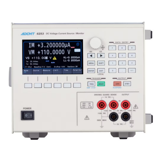
ADCMT 6253 Operation Manual (274 pages)
DC Voltage Current Source/Monitor
Brand:
ADCMT
| Category:
Monitor
| Size: 7 MB
Table of Contents
Table of Contents
9
List of Illustrations
15
Preface
19
Product Overview
19
Output Range
20
Standard Accessory List
21
Supplied Accessories
21
Optional Accessories
22
Optional Accessory List
22
Environmental Conditions
23
Operating Environment
23
Operating Environment
24
Power Specification
25
Power Supply Specification
25
Setting Power Voltage Indicator
25
Changing Power Voltage, and Checking or Replacing Power Fuse
26
Power Cable
27
Connecting Power Cable
28
Operating Check
28
Self Test Completion
29
Self-Test in Progress
29
Start-Up Screen
30
VSIM Measurement Display (Output ON)
30
Cleaning, Storage, and Transport Methods
31
Storage
31
Transport
31
Calibration
32
Life Limited Parts
32
Warm-Up
32
1.10 Product Disposal and Recycling
33
Front and Rear Panels
35
Panel and Operation
35
2.1.2 Rear Panel
37
Display
39
Home Screen
39
Soft Keys
41
Soft Keys at DC or Pulse Source (Top Layer)
41
Soft Keys at Sweep Source (Top Layer)
41
Basic Operation
45
Numerical Input
45
Numerical Input with Right and Left Keys and Rotary Knob
45
Numerical Input in Direct Input Mode
46
DC Source and Measurement
47
Example Operations
47
Pulse Source and Measurement
49
Sweep Measurement
53
MENU Hierarchy
57
MENU Hierarchy Operation
57
MENU Operation
57
Menu Structure and Parameter List
58
Sweep Memory Settings (Random Sweep)
67
Measurement Data Graph Display
68
Menu Index
71
Function Description
73
MENU Key (Parameter Setting)
73
Fixed Sweep
75
Linear Sweep
75
Multi-Slope Linear Sweep
77
ENTER Key
85
EXIT Key/Local Key
85
Keys (Right and Left Keys)
85
SHIFT Key (Shift Mode)
85
Soft Keys
85
HOLD Key (Trigger Mode)
86
TRIG Key and SWP STOP Key (Trigger/Sweep Stop)
86
DATA ENTRY Keys (Numerical Data Input)
87
OPR Key/Suspend Key (Operate/Suspend)
87
STBY Key (Output Standby)
87
DUT Connection
89
Internal Connection
89
Output Terminals (Front and Rear Output Terminals)
89
Technical References
89
Remote Sensing (2-Wire/4-Wire Connection)
90
Preventing 6253 Oscillation
92
Preventing Oscillation
92
Reducing Stray Capacitance and Lead Inductance
93
Preventing 6253 Oscillation
94
Preventing DUT Oscillation
94
Connection for High Current Measurement
95
Connection with 12701A
96
Connection with Fixture 12701A
96
Functions in Detail
97
Operations in DC Source Mode
97
4.2.1 Operations in DC Source Mode
98
Operations in Pulse Source Mode
99
Operations in Sweep Source Mode
102
Operations in DC Sweep Source Mode
105
Operations in Pulse Sweep Source Mode
107
Random Sweep and Random Pulse Sweep
109
Multi-Slope Linear Sweep
110
Multi-Slope Linear Pulse Sweep
111
Reverse Function
112
Reverse Operations in DC Sweep Mode
112
Output Value at Sweep Stop
113
Reverse Operations in Pulse Sweep Mode
113
Source Function
114
Source Mode, Source Function and Setting Parameters
114
Restrictions on Switching Source Function
115
Source Range
115
Source Value Restrictions
115
Source Range
116
HV (High Voltage) Display
117
Operate, Standby and Suspend
118
Output Status Transitions
118
Output Status and Internal Setting Values
119
Measurement Function
121
Measurement Ranging
121
Source Value Monitor
121
Measurement Delay Time and Measurement Value
127
Auto Zero Function
128
Limit (Compliance)
129
Limit Setting Ranges
129
Rechargeable Battery Charge and Discharge Operations
130
Setting Limit Values
130
Displaying and Outputting of Limit Detection
131
4.2.7 Alarm Detection
132
Alarm Detection Contents
132
Oscillation Detection
132
Basic Source and Measurement Timing
133
Oscillation Detection Sensitivity
133
Source and Measurement Timing
133
Restrictions on Time Parameters
134
Measurement Delay and Settling Time
139
Settling Time and Measurement Delay Time
139
Integration Time and Processing Time
141
NULL Calculation Timing
145
External Control Signal Functions
149
Restrictions on Tp, Tp (Ext), Th, and Th (Ext)
151
TA Value
151
Restrictions on Top
152
Settings for 3-Unit Synchronous Operation by SYNC out
153
Connections for 3-Unit Synchronous Operation by SYNC out
154
Serial Connection
157
Parallel Connection
158
Conceptual Diagram of Memory Store
159
Comparison of Memory Store Operations
160
Self-Test Items
162
Standard Bus Cable
174
Communication Settings When Using LAN
175
LAN Setting Items
175
Device Event Status Register (DESR)
182
Error Event Register (ERR)
182
Standard Event Status Register (SESR)
182
Status Register Structure
183
Status Byte Register Structure
184
Status Byte Register (STB)
185
Connections for Calibration
225
Calibration Procedure
228
Calibration Procedure
229
Calibration Procedure
230
Calibration Procedure
231
Calibration Procedure
232
Calibration Procedure
233
Calibration Procedure
234
Interface Function
251
Items to be Inspected before Requesting the Repair
259
A.2 Error Message List
261
Advertisement
Advertisement
Related Products
ADCMT 6241A
ADCMT 6242
ADCMT 6240B
ADCMT 6247G
ADCMT 6247C
ADCMT 6243
ADCMT 6244
ADCMT 6166
ADCMT 6146
ADCMT 6156
ADCMT Categories
Measuring Instruments
Multimeter
Monitor
Portable Generator
Accessories
More ADCMT Manuals
Login
Sign In
OR
Sign in with Facebook
Sign in with Google
Upload manual
Upload from disk
Upload from URL