Sign In
Upload
Manuals
Brands
ADC Manuals
Industrial Equipment
PG-Flex Plus
ADC PG-Flex Plus Manuals
Manuals and User Guides for ADC PG-Flex Plus. We have
2
ADC PG-Flex Plus manuals available for free PDF download: Installation Manual, Technical Practice
ADC PG-Flex Plus Installation Manual (64 pages)
Brand:
ADC
| Category:
Touch terminals
| Size: 1 MB
Table of Contents
Using this Technical Practice
4
Inspecting Your Shipment
4
Table of Contents
5
Overview
13
PCS-719 Supported System Configurations
13
Figure 1. PCS-719 Shelf with ASU-945 DS3 Splitter
13
Table 1. PCS-719 Supported System Configurations
13
96-Channel Universal DAML COT
14
Figure 2. 96-Channel Universal DAML COT
14
192-Channel Integrated PG-Flexplus COT
15
Figure 3. 192-Channel Integrated COT
15
96-Channel Universal DLC COT to Plus RT
16
Figure 4. 96-Channel Universal DLC COT
16
192-Channel Distributed DLC RT
17
Figure 5. 192-Channel Distributed DLC RT
17
Edge RAM
18
Figure 6. Edge RAM System Configuration - AMX-943
19
Figure 7. Edge RAM System Configuration - AMX-944
19
Edge IAD
20
Figure 8. Edge IAD System Configuration - AMX-943
21
Figure 9. Edge IAD System Configuration - AMX-944
21
Description and Features
22
Features
22
Figure 10. PCS-719 Card Placement
22
Backplane Connections
23
Figure 11. PCS-719 Shelf Backplane
23
Table 2. Backplane Connectors
23
Connector by Type and Function
24
Power
24
Ds1
24
Ds3
24
Hdsl
24
Two-Wire Subscriber Circuits
24
Alarm Cutoff
25
External Alarm Relay Contacts
25
Figure 12. Alarm Relay Contacts and Alarm Block Diagram
25
External Environmental Alarm Contact Alarm Inputs/Outputs
26
Figure 13. ENV Alarm Input Pinouts
26
Supported NID/RT Service Types
27
Table 3. Environmental Alarm Input Definitions
27
Table 4. DB-25 Alarm Cable Pinouts
27
Table 5. Supported NID/RT Service Types
27
Fusing and Heat Dissipation
28
Fusing 192-Channel Integrated COT or 192-Channel Distributed DLC RT Systems
28
Table 6. PCS-719 Shelf Power and Heat Dissipation for Integrated Systems
28
Fusing Universal DAML Systems
29
Table 7. PCS-719 Shelf Power and Heat Dissipation for Universal Systems
29
Fusing CPOTS Systems
30
Fusing RPOTS Systems
30
Table 8. PCS-719 Shelf Power and Heat Dissipation for CPOTS
30
Table 9. PCS-719 Shelf Power and Heat Dissipation for RPOTS
30
Fusing Edge RAM and Edge IAD Systems
31
Table 10. PCS-719 Shelf Power and Heat Dissipation for Edge RAM and Edge IAD
31
Network Interface
32
Figure 14. Modem Connection for PCS-719 Backplane
32
Table 11. PCS-719 Backplane DB-25 Connector Pinouts
32
LAN Interface
33
DSX-1 Connections
33
Figure 15. Null Modem Connection for PCS-719 Backplane
33
Figure 16. LAN Connector
33
DS3 Connections (for AMX-944 Only)
34
Specifications
34
Table 12. Specifications
34
Upgrading the PCS-719 L1A to L3
35
Required Tool
35
Installing the ASU-945 DS3 Splitter
35
Figure 17. Remove Screws and Lock Washers
35
Figure 18. Replace the Screws and Lock Washers
35
Installation and Test
36
Required Tools and Test Equipment
36
Required for All Shelf Installations
36
Mounting
36
NEBS Compliance
36
Ground Connections
37
J22 Connection
37
TB1 FGND Connection
37
Power Connections
37
Single Source Powering
38
Figure 19. Single Source Power Wiring
38
Redundant Shelf Powering
39
Figure 20. Redundant Shelf Power Wiring
39
Split Shelf Powering
40
Figure 21. Split-Shelf Wiring
40
Alarm Output Connections
41
Figure 22. Connecting the Alarm Relays
41
Table 13. Alarm Terminations
41
Test Connections
42
External ACO Connection
42
External Environmental Alarm Input Cable
42
Figure 23. Connecting the Test Pair and External ACO Switch
42
Application-Specific Shelf Installations
43
96-Channel Universal DAM
43
192-Channel Integrated COT
43
96-Channel Universal DLC COT/RT
43
192-Channel Distributed DLC RT
43
Edge RAM
43
Edge IAD
43
DS0 Connections
44
DSX-1 Connections
44
Figure 24. DSX-1 Backplane Terminations
45
DS3 Connections (for PCS-719 List 3 Only)
46
HDSL Wiring
46
Figure 25. DS3 Terminations
46
Figure 26. Connecting the HDSL Pairs
47
Table 14. P1 Telco Connector Pinouts
48
Table 15. P2 Telco Connector Pinouts
48
Table 16. P3 Telco Connector Pinouts
49
Table 17. P4 Telco Connector Pinouts
49
Table 18. PCS-719 HDSL Connections
50
Turn-Up and Test
51
Table 19. P1 Tip and Ring Pin Assignments
54
Table 20. P2 Tip and Ring Pin Assignments
55
Table 21. P3 Tip and Ring Pin Assignments
56
Table 22. P4 Tip and Ring Pin Assignments
57
Acronyms
59
Product Support
61
Technical Support
61
Limited Warranty
61
Returns
61
Fcc Classa Compliance
62
Modifications
62
Advertisement
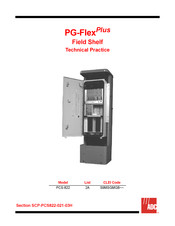
ADC PG-Flex Plus Technical Practice (46 pages)
Field Shelf
Brand:
ADC
| Category:
Industrial Equipment
| Size: 2 MB
Table of Contents
Using this Technical Practice
4
Inspecting Your Shipment
4
Table of Contents
5
Overview
11
Figure 1. Field Shelf Mounted in the Marconi NCAD16C Pedestal
11
Table 1. PCS-822 Card Types/System Types
11
Features
12
Figure 2. PCS-822 Block Diagram
12
PCS-822 Field Shelf Application Configurations
13
Figure 3. PCS-822 Application - 4/6 Channel Systems
13
Figure 4. PCS-822 Application - 24 Channel Systems
14
Figure 5. PCS-822 Application - 4/6/24 Channel Systems
15
Figure 6. PCS-822 Application - RPOTS
16
Figure 7. PCS-822 Application - Edge IAD
17
Figure 8. PCS-822 Application - Edge RAM
18
Figure 9. PCS-822 Application - Edge IAD and Edge RAM
19
Figure 10. PCS-822 Application - 4/6/24 Channel Systems, Edge IAD and RAM Systems
20
Alarms
21
Figure 11. Alarm Circuits
21
Specifications
22
Table 2. Specifications
22
Installation and Test
23
Required Tools and Test Equipment
23
Hardware Included with the Kit
23
Table 3. Cable Wire Gauge and Length
23
Installing the Brackets
24
Figure 12. Mounting the Brackets
24
Preparing the Field Shelf
25
Figure 13. Preparing the Field Shelf
25
Attaching the Field Shelf
26
Figure 14. Mounting the Field Shelf
26
Figure 15. Securing the Field Shelf
26
PCS-822 Ground Connections
27
Figure 16. NCAD-16-C Divider Panel and Ground Clamp Assembly
27
Figure 17. Ground Clamp
27
Figure 18. Mounting the Ground Bar to the Pedestal
28
Cable Locations
29
Figure 19. Field Shelf Cable and Fan Unit Installation
29
PFU-830 Fan Unit
30
Figure 20. PFU-830 Fan Unit
30
PCT-850 Cards
31
Figure 21. PCT-850 Card
31
Network Lines
32
Table 4. Network Screened Cable Circuit Assignments
33
DSL Lines
34
Table 5. DSL Cable Circuit Assignments
34
Subscriber Cable
35
Table 6. Subscriber Cable Circuit Assignments
35
Alarm Leads
37
Table 7. Alarm Cable Circuit Assignments
37
Protection Block
38
Figure 22. Protection Block
38
Power
39
DC Power Connections
39
Figure 23. PCS-822 3-Pair Power Cable
39
Table 8. Power Cable
39
Powering the System
40
Table 9. PCS-822 Field Shelf Power Consumption and Heat Dissipation
40
Acronyms
41
Product Support
43
Technical Support
43
Limited Warranty
43
Returns
43
Fcc Classb Compliance
44
Modifications
44
Advertisement
Related Products
ADC PCS-822
ADC PG-PLUS
ADC PG-FlexPlus PG-CAB001
ADC PWR-AVIS
ADC PowerWorx 70 Series
ADC PowerWorx Select Series
ADC ProAX LTC Series
ADC ProAx JTC Series
ADC PG-FLEXPLUS PLL-735
ADC PG-PLUS PRL-779
ADC Categories
Network Hardware
Dryer
Medical Equipment
Thermometer
Blood Pressure Monitor
More ADC Manuals
Login
Sign In
OR
Sign in with Facebook
Sign in with Google
Upload manual
Upload from disk
Upload from URL