Sign In
Upload
Manuals
Brands
ACOEM Manuals
Measuring Instruments
Met One Instruments GAS-1060
ACOEM Met One Instruments GAS-1060 Manuals
Manuals and User Guides for ACOEM Met One Instruments GAS-1060. We have
1
ACOEM Met One Instruments GAS-1060 manual available for free PDF download: User Manual
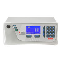
ACOEM Met One Instruments GAS-1060 User Manual (164 pages)
Direct Nitrogen Dioxide Analyzer US EPA Designated Equivalent Method
Brand:
ACOEM
| Category:
Measuring Instruments
| Size: 6 MB
Table of Contents
Table of Contents
3
Manufacturer's Statement
11
Notice
11
Safety Requirements
12
Warranty
12
Service & Repairs
13
CE Mark Declaration of Conformity
14
Claims for Damaged Shipments and Shipping Discrepancies
15
Internationally Recognised Symbols on Ecotech Equipment
16
Manual Revision History
17
Table 1 - Manual Revision History
17
Introduction
19
Description
19
Specifications
19
Measurement
19
Precision/Accuracy
19
Calibration
20
Power
20
Operating Conditions
20
Communications
20
Physical Dimensions
21
Nomenclature
21
Background/Theory
22
Measurement Theory
23
Figure 1 - Simple Pneumatic Diagram
23
Instrument Description
24
Calibration Valve Manifold
24
Background Scrubber DAU
24
Sample Filter Holder
24
Figure 2 - Internal Components Diagram
24
Sample DFU
25
Dryer
25
Pressure Sensor PCA
25
Interface PCA
25
Measurement Cell Assembly
25
Pneumatic Tubing
26
Main Controller PCA
26
Power Supply
26
On/Off Switch
26
Figure 3 - Ecotech Tygon Tubing
26
Communications
27
Installation
29
Initial Check
29
Figure 4 - Opening the Instrument
29
Installation Notes
30
Instrument Set-Up
31
Pneumatic Connections
31
Figure 5 - Instrument Back Panel
31
Power Connections
32
Communications Connections
32
Instrument Set-Up
33
Transporting/Storage
33
Figure 6 - Installation of USB Memory Stick
34
Figure 7 - Switching the Battery On/Off
35
Operation
37
Warm-Up
37
Measurement
37
General Operation Information
37
Keypad & Display
37
Table 2 - Measurements Times
37
Figure 8 - Front Panel
38
Home Screen
39
Figure 9 - Home Screen
39
Menus & Screens
40
Quick Menu
41
Main Menu
41
Analyser State Menu
42
Status Menu
42
Temperature Menu
43
Pressure & Flow Menu
44
Voltage Menu
44
General Settings Menu
44
Measurement Settings Menu
45
Calibration Menu
46
Pressure Calibration Menu
48
Service Menu
48
Diagnostics Menu
49
Digital Pots Menu
49
Internal Pump Menu (Option)
50
Valve Menu
50
Tests Menu
51
Digital Input Test Menu
51
Digital Output Test Menu
52
Calculation Factors Menu
52
Communications Menu
53
Data Logging Menu
53
Serial Communication Menu
53
Analog Input Menu
54
Analog Output Menu
54
Digital Input Menu
56
Digital Output Menu
56
Network Menu
57
Table 3 - Digital Output States
57
Bluetooth Menu
58
Advanced Menu
59
Hardware Menu
59
Parameter Display Menu
60
Communications
61
RS232 Communication
61
Figure 10 - Communication Ports
61
USB Communication
62
Figure 11 - Multidrop RS232 Cable Example
62
TCP/IP Network Communication (Optional)
63
Figure 12 - Example of Typical Network Setups
63
Network Setup
64
Port Forwarding on Remote Modem/Router Setup
64
Figure 13 - Example of Network Menu Setup
64
Setup Airodis to Communicate with Serinus
65
Figure 14 - Port Forwarding Example
65
Figure 15 - LAN Network Set-Up (Airodis)
65
Digital/Analog Communication
66
Analog Outputs
66
Figure 16 - WAN Network Set-Up (Airodis)
66
Table 4 - Analog Outputs
66
Analog Inputs
68
Digital Status Inputs
68
Digital Status Outputs
68
Figure 17 - 25 Pin Rear Panel PCA (Default Jumpers Highlighted)
68
Logging Data
69
Configure Instrument Internal Logging
69
Figure 18 - External 25 Pin I/O Individual Pin Descriptions
69
Using Airodis Software to Download Data
70
Connecting the Instrument to Your PC
70
Figure 19 - Installing Driver Software (Device Manager)
70
Figure 20 - Update Driver Popup
71
Figure 21 - Update Driver Popup (Directory Location)
71
Figure 22 - Installing Driver Confirmation Prompt
72
Figure 23 - Successful Driver Installation
72
Installing Airodis
73
Configuring Airodis
73
Figure 24 - Airodis Workspace Manager
74
Figure 25 - Adding a New Station
74
Figure 26 - New Station Connection
75
Table 5 - New Station Setup
75
Figure 27 - Station Configuration
76
Figure 28 - Error Status Notification
76
Figure 29 - Downloading Data
77
Figure 30 - Download Data Status
77
Figure 31 - Data Visibility
78
Figure 32 - Exporting Data
78
Serinus Remote App/Bluetooth
79
Installation
79
Figure 33 - Data Download Complete
79
Connecting to the Instrument
80
Figure 34 - Downloading the App from Google Play Store
80
Figure 35 - Bluetooth Pairing Request
80
Instrument Control
81
Figure 36 - Showing or Hiding the Numpad
81
Real-Time Plot
82
Figure 37 - Switching Analysers
82
Figure 38 - Real-Time Plot
83
Download
84
Get Parameters
84
Figure 39 - Plot of Downloaded Data
84
Preferences
85
Figure 40 - Directory Settings
85
Figure 41 - Logs Format
85
Figure 42 - Colour Theme Settings
86
Calibration
87
Overview
87
Figure 43 - Example of a Calibration System
87
Pressure Calibration
89
Full Pressure Calibration
89
Ambient Point Pressure Calibration
90
Figure 44 - Setting the Ambient Set Point
90
Pressure Calibration (Internal Pump Option Only)
91
Zero Calibration
91
Calibration Port
92
Sample Port
92
Internal Zero (Sample Port)
93
Span Calibration
93
Calibration Port
93
Sample Port
94
Manual Instrument Gain and Offset Adjustments
94
Precision Check
95
Multipoint Precision Check
95
High Pressure Zero/Span Valve
97
Figure 45 - Multipoint Calibration Results Example
97
Single Pressurised Calibration Option
98
Figure 46 - Single High Pressure Calibration Option
98
Dual Pressurised Calibration Option
100
Figure 47 - Dual High Pressure Calibration Option
100
Service
103
Maintenance Tools
103
Figure 48 - Minifit Extraction Tool - (T030001)
103
Figure 49 - Orifice/Sintered Filter Removal Tool - (H010046)
103
Maintenance Schedule
104
Figure 50 - Leak Test Jig - (H050069)
104
Figure 51 - Air Monitoring Test Equipment Kit (AMTEK) - Customisable
104
Table 6 - Maintenance Schedule
104
Maintenance Procedures
106
Background Scrubber DAU Check
106
Particulate Filter Replacement
107
Clean Fan Filter
107
Figure 52 - Removing the Plunger
107
Sample DFU Replacement
108
Background Scrubber DAU Replacement
108
Figure 53 - Removing the Fan Filter
108
Figure 54 - Sample DFU
108
Leak Check
109
Figure 55 - Background DAU
109
Clean Pneumatics
111
Pressure Sensor Check
111
Figure 56 - Test Point Location
112
Figure 57 - Typical Test Point Reading of Internal Pump Pressure Sensor
112
Bootloader
113
Display Help Screen
113
Communications Port Test
113
Figure 58 - Typical Test Point Reading of Measurement Cell Pressure Sensor
113
Updating Firmware
114
Erase All Settings
114
Start Analyser
114
Troubleshooting
115
Table 7 - Troubleshoot List
115
Leak Check
117
Figure 59 - Leak Check Troubleshooting Flow Chart
117
Flow Fault
118
Figure 60 - Zero Flow Fault Troubleshooting Flow Chart
118
Noisy/Unstable Readings
119
Figure 61 - Noisy or Unstable Readings Troubleshooting Flow Chart
119
Flow Block Temperature Failure
120
Figure 62 - Flow Block Temp Failure Troubleshooting Flow Chart
120
Measurement Cell Temperature Failure
121
Figure 63 - Measurement Cell Temperature Failure Troubleshooting Flow Chart
121
USB Memory Stick Failure
122
Figure 64 - USB Memory Stick Failure
122
Ecotech Service Support Files
123
Figure 65 - USB Memory Stick File Structure
124
Optional Extras
125
Dual Sample Filter (PN: E020100)
125
Internal Pump (PN: E020124)
125
Hardware Setup
125
Figure 66 - Dual Filter Option Installed
125
Pressure Calibration
126
Pump Control
126
Rack Mount Kit (PN: E020116)
126
Table 8 - Included Parts (Rack Mount Kit)
126
Figure 67 - Separate Rack Slides
127
Figure 68 - Assemble Inner Slide on Chassis
127
Figure 69 - Rack Mount Ears Fitted to Instrument
128
Figure 70 - Attach Rack Mount Adaptors to Outer Slides
128
Figure 71 - Test Fit the Rack Slide Assembly into Your Rack
129
Figure 72 - Attach Slides to Front of Rack
129
High Pressure Zero/Span Valves
130
Figure 73 - Slide Clips
130
Parts List
131
Serinus Accessories Kit
131
Maintenance Kit
131
Table 9 - Serinus Accessories Kit (PN: H010136)
131
Table 10 - Annual Maintenance Kit - (PN: E020203-01)
131
Consumables
132
Instrument Parts List
132
Table 11 - Consumables
132
Table 12 - Spare Parts List
132
Plumbing Schematic - (PN: D020060)
134
Block Wiring Schematic - (PN: D020111)
135
Measurement Cell Side Section - (PN: H015000)
136
Calibration Valve Manifold Assembly Exploded View - (PN: H010013-01)
138
Valve Assembly Exploded View - (PN: H010042)
139
High Pressure Valve Exploded View - (PN: H050043)
140
Table 13 - Packet Format
141
Table 14 - Example: Primary Gas Request
141
Table 15 - Example: Primary Gas Response
142
Table 16 - Example: Primary Gas Response (Continued)
142
Table 17 - List of Errors
142
Table 18 - Example: Get IEEE Response Data
143
Table 19 - Advanced Protocol Parameter List
144
Table 20 - Bayern-Hessen Data
157
Table 21 - Block Check Operation
158
Table 22 - Status Bit Map
159
Table 23 - Failure Bit Map (Positive Logic)
160
Table 24 - Modbus Error Codes
163
Advertisement
Advertisement
Related Products
ACOEM Met One Instruments E-Sampler V2
ACOEM 1-0897 T21
ACOEM 1-1063 P1
ACOEM 1-1216 M7
ACOEM 1-1217 S7
ACOEM 1-1263 M9
ACOEM 1-1264 S9
ACOEM 1-1278 M10
ACOEM 1-1279 S10
ACOEM AT Series
ACOEM Categories
Measuring Instruments
Security System
Tools
Laboratory Equipment
Samplers
More ACOEM Manuals
Login
Sign In
OR
Sign in with Facebook
Sign in with Google
Upload manual
Upload from disk
Upload from URL