Sign In
Upload
Manuals
Brands
ABB Manuals
Circuit Tester
Emax E1.2
ABB Emax E1.2 Manuals
Manuals and User Guides for ABB Emax E1.2. We have
4
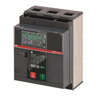
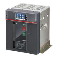
ABB Emax E1.2 manuals available for free PDF download: Installation, Operation And Maintenance Instructions For The Installer And The User, Manual, Retrofitting Manual
ABB Emax E1.2 Installation, Operation And Maintenance Instructions For The Installer And The User (109 pages)
low voltage air circuit-breakers
Brand:
ABB
| Category:
Circuit Tester
| Size: 14.62 MB
Table of Contents
Table of Contents
3
Emax E1.2 Circuit-Breakers
6
Contents
6
Organization of this Handbook
6
Intended Readership
6
Instructions
6
Integrated Informations
6
Warnings
7
Standards
8
Transport and Checking on Receipt
9
Introduction
9
Weight of the Circuit-Breakers with Packaging
9
Transport of the Packaged Circuit-Breaker
9
Identification of Packaging
10
Packaging Checks
10
Damage and Discrepancy Report
10
Storage Method
11
Unpacking and Handling
12
Opening the Packaging
12
Weight of Circuit-Breakers Without Packaging
13
Disposal of Packing Materials
13
Description
14
Description of Circuit-Breaker
14
Description of the Circuit-Breaker Front Panel
15
Description of Electrical Data Plate IEC
15
Description of Electrical Data Plate UL
16
Manual Operations for Opening and Closing the Circuit-Breaker
17
Mechanical Status Indicators
19
Circuit Breaker Racking-In/Racking-Out Operations
20
Mechanical Position Indicators
22
Environmental Conditions
23
Installation Environment
23
Temperatures of the Installation Environment
23
Particular Weather Conditions
23
Dusty Environments
23
Vibration
23
Altitude
24
Electromagnetic Compatibility
24
Storage Environment
24
Installation
25
Warnings and Precautions before the Installation
25
Mounting of the Fixed Circuit-Breaker
25
Mounting Anti-Insertion Locks
25
Mounting the Fixed Part of the Withdrawable Circuit-Breaker
26
Types of Terminal
26
Change of Position of the Vertical/Horizontal Terminals
29
Connection to the Power Circuit
30
Dimensions
31
Positioning Anchor Plates
32
Introduction to Ekip Protection Trip Units
33
Presentation
33
Families and Functionality
33
Protections
34
Measurements
34
Controller
35
Accessorizing Modules
35
Integrated Functions: Self-Diagnosis, Test and Power Controller
35
Ekip Dip Protection Trip Unit
36
Operator Interface
36
Introduction
36
Components of the Interface
36
Leds
37
Protections: Thresholds
37
Protections: Times
37
Settings
37
Itest Pushbutton
38
Test Connector
38
Protections
39
L Protection
39
S Protection
40
I Protection
41
G Protection
42
Neutral and Frequency
43
Additional Protections
44
Summary Table of Protections
45
Measurements
46
Introduction Measurements
46
Instantaneous Currents
46
Maximum and Minimum Currents
46
Trips
46
Contact Wear
46
Number of Operations
46
Test
47
Presentation
47
LED Test
47
Battery Test
47
Protection Test
47
Opening Test
47
List of Alarms and Signals
48
LED View
48
Summary Table of LED Signals
49
Ekip Dip: Additional Functions
51
Maintenance
51
Local Bus
51
Date and Time
51
Programmable States
51
Circuit-Breaker Label and User Data
51
Info Page
51
Date of Installation
51
Load Profile Timers
51
Energy Store Time
52
Led Alive
52
Open/Close Remote Direct Command
52
Modules Network Settings Retention
52
Wink
52
Glitch
52
Operating Features
53
Primary Operating Currents
53
Auxiliary Power Supply
53
Default Parameters
54
Ekip Dip Default Parameters
54
Accessories
55
Preliminary Considerations
55
Introduction
55
Accessory Combination Tables
55
Circuit-Breaker Dismantling Operations
57
Circuit Diagrams
58
General Wiring Diagrams
58
Circuit-Breaker Terminal Box
59
Electronic Accessories
64
Ekip Supply Modules
64
Description
64
Compatibility
64
Electrical Characteristics
64
Connections
65
Signallings
65
Ekip Link Module
66
Description
66
Compatibility and Power Supply
66
Connections
67
Signallings
68
Ekip Com Actuator Module
69
Description
69
Connections
69
Compatibility
69
Other Accessories
70
Ekip LCD
70
Rating Plug
70
Ekip Connect Software
70
Ekip Bluetooth Module
71
Ekip T&P Module
71
Module Ekip Programming
72
Ekip TT Module
72
Ekip Signalling 10K Modules
73
Ekip Signalling Modbus TCP
73
Ekip Multimeter Module
74
External Neutral
74
Contacts Ekip AUP
74
Ekip RTC Contact
74
Electrical Accessories
75
Electrical Control Accessories
75
YO-YC-YO2: Opening and Closing Coil
75
YU: Undervoltage Coil
77
YR: Remote Resetting Coil
78
M: Motor
79
Electrical Signalling Accessories
80
Aux 4Q: Auxiliary Open-Closed Contacts
80
Aux 15Q: External Additional Open/Closed Auxiliary Contacts
81
AUP: Auxiliary Position Contacts
82
RTC: Ready to Close Signalling Contact
83
S51: Trip Unit Tripping Signalling Contact
84
S33 M/2: Springs Charged Signalling Contact
85
Mechanical Accessories
86
Mechanical Protection Accessories
86
PBC: Opening and Closing Pushbutton Protection
86
IP54 Protection
86
HTC / LTC: Terminal-Covers
87
PB: Phase Separators
87
Mechanical Safety Accessories
88
KLC: Open Position Key Lock
88
PLC: Padlock
88
Anti-Insertion Lock
88
MOC: Operation Counter
88
PLP: Padlock in Connected/Test/Disconnected Positions
89
KLP: Key Lock for Connected/Test/Disconnected Positions
89
KLP Lock Additional Accessory
89
SL: Shutter Lock
90
DLC: Door Opening Lock with the Circuit-Breaker in Closed Position
90
Fail Safe
90
Mechanical Interlocks
91
Mechanical Interlock of Type a - Two Circuit-Breakers
91
Putting into Service and Maintenance
92
Putting into Service
92
Introduction
92
General Checks
92
Wizard
93
Procedures for Checking the Accessories
93
Final Check List
95
Identification of Alarms or Failures
96
Introduction
96
Faults, Causes and Remedies
97
Faults Signalled on the Display
100
Maintenance
101
Safety Standards
101
Skilled Personnel
101
Circuit-Breaker Life
102
Maintenance Schedule
102
Maintenance Operations
103
Preliminary Operations
103
Inspections and General Cleaning
103
Circuit-Breaker Connections and Connections between Circuit- Breaker and Switchboard
103
Disassembly Operations
104
Cleaning and Lubrication of the Operating Mechanism
105
Inspection of Electrical and Mechanical Accessories
105
Inspection of the Protection Trip Unit
105
Test with Ekip Connect
106
Final Checks
106
Interlock Check
106
Decommissioning and Treatment at End of Life
107
Safety Standards
107
Trained Personnel
107
End of Life Treatment for Circuit-Breaker Materials
107
Disposal of Packing Materials
107
Advertisement
ABB Emax E1.2 Installation, Operation And Maintenance Instructions For The Installer And The User (67 pages)
LOW VOLTAGE AIR CIRCUIT-BREAKERS
Brand:
ABB
| Category:
Circuit breakers
| Size: 9.44 MB
Table of Contents
Table of Contents
3
Glossary
5
Introduction
6
Contents
6
Safety
7
Regulations
8
Management Operations
9
Transport and Checking on Receipt
9
Unpacking and Handling
12
Description
14
Environmental Conditions
22
Installation
22
Ekip Dip
30
General Characteristics
30
Operating Features
31
Operator Interface
32
Protections - Introduction
35
Measurements
42
Test
43
List of Alarms and Signals
44
Additional Functions
46
Default Parameters
46
Accessories
47
Overview
47
Rating Plug
48
Putting into Service and Maintenance
49
Putting into Service
49
Identification of Alarms or Failures
54
Maintenance
58
Maintenance Operations
60
Lubrication of Jaw-Type Isolating Contacts of Withdrawable Circuit-Breaker
64
Decommissioning and Treatment at End of Life
65
ABB Emax E1.2 Manual (15 pages)
Brand:
ABB
| Category:
Circuit breakers
| Size: 5.96 MB
Advertisement
ABB Emax E1.2 Retrofitting Manual (10 pages)
Brand:
ABB
| Category:
Circuit breakers
| Size: 14.19 MB
Advertisement
Related Products
ABB Emax E1.2-A
ABB E1.2N
ABB MicroFlex e150
ABB MotiFlex e180
ABB E1B 08
ABB E1B 10
ABB E1N 10
ABB E1N 12
ABB E1N 16
ABB E1B 12
ABB Categories
Industrial Equipment
Controller
Measuring Instruments
Battery Charger
DC Drives
More ABB Manuals
Login
Sign In
OR
Sign in with Facebook
Sign in with Google
Upload manual
Upload from disk
Upload from URL