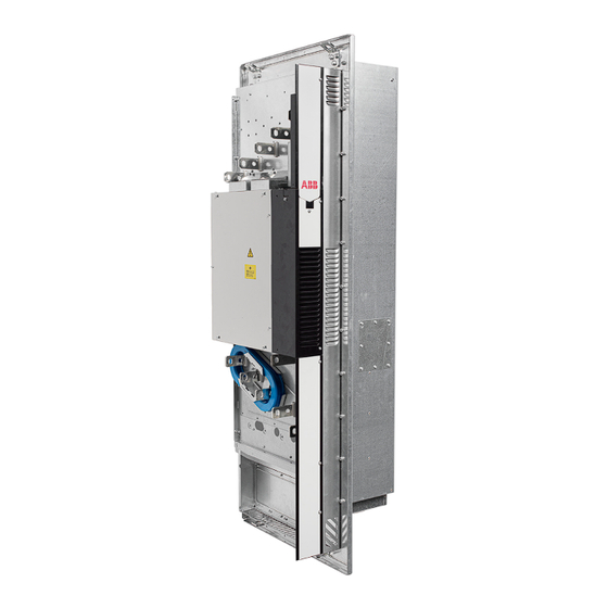
Sign In
Upload
Manuals
Brands
ABB Manuals
DC Drives
ACS880-04FXT
ABB ACS880-04FXT Manuals
Manuals and User Guides for ABB ACS880-04FXT. We have
3
ABB ACS880-04FXT manuals available for free PDF download: Hardware Manual, Electrical Planning Manual, Application Manual
ABB ACS880-04FXT Hardware Manual (196 pages)
Drive module packages
Brand:
ABB
| Category:
DC Drives
| Size: 32.36 MB
Table of Contents
Table of Contents
5
Table of Contents
7
1 Safety Instructions
13
Contents of this Chapter
13
Use of Warnings and Notes
13
General Safety in Installation, Start-Up and Maintenance
14
Electrical Safety in Installation, Start-Up and Maintenance
15
Electrical Safety Precautions
15
Additional Instructions and Notes
16
Optical Components
17
Printed Circuit Boards
17
Grounding
18
General Safety in Operation
19
Additional Instructions for Permanent Magnet Motor Drives
19
Safety in Installation, Start-Up, Maintenance
19
Safety in Operation
20
2 Introduction to the Manual
21
Contents of this Chapter
21
Applicability
21
Target Audience
21
Purpose of the Manual
21
Related Documents
22
Categorization by Frame Size and Option Code
23
Quick Installation, Commissioning and Operating Flowchart
23
Terms and Abbreviations
24
3 Operation Principle and Hardware Description
25
Contents of this Chapter
25
Product Overview
26
Drive Connection Examples
27
Layout
29
Standard Drive Module Configuration
29
Drive Module Configuration with IP20 Shrouds (Option) and Full-Size Output Cable Connection Terminals (Option)
30
Control Unit
31
Overview of Power and Control Connections
32
External Control Unit Connection Cables
34
Type Designation Labels
35
Drive Module Package Label
35
Drive Module Label
36
Type Designation Key
37
Drive Module Package
37
Drive Module
38
4 Generic Cabinet Planning Instructions
41
Contents of this Chapter
41
Limitation of Liability
41
Cabinet Construction
41
Disposition of the Devices
41
Grounding of Mounting Structures
42
Busbar Material and Joints
42
Shrouds
42
Tightening Torques
42
Electrical Connections
42
Mechanical Connections
42
Insulation Supports
43
Cable Lugs
43
Cooling and Degrees of Protection
43
Planning the Cooling
43
Air Inlets and Outlets
43
Preventing the Recirculation of Hot Air
44
EMC Requirements
45
Attaching the Cabinet
47
Cabinet Placement on a Cable Channel
47
Cubicle Heaters
47
Mounting the Control Panel on the Cabinet Door
47
5 Guidelines for Planning the Mechanical Installation
49
Contents of this Chapter
49
Installation Alternatives
49
Channel Installation
49
Basic Requirements for the Channel Wall
49
Installation Principle
50
Cabinet Installation
51
Layout Example, Outside View
51
Layout Example, Inside View
52
Other Installation Positions than Vertical
52
Required Free Space
53
6 Mechanical Installation
55
Contents of this Chapter
55
Examining the Installation Site
55
Moving and Unpacking the Unit
55
Unpacking
55
Package Drawings
56
Examining the Delivery
58
Lifting
58
Attaching Alternatives
59
Attaching the Drive Module by the Flange
59
Attaching the Drive Module by the Heatsink
60
Attaching the External Control Unit
60
7 Guidelines for Planning the Electrical Installation
61
Contents of this Chapter
61
Limitation of Liability
61
Selecting the Main Supply Disconnecting Device
61
European Union
61
North America
62
Other Regions
62
Selecting the Main Contactor
62
Examining the Compatibility of the Motor and Drive
62
Protecting the Motor Insulation and Bearings
62
Requirements Table
63
Availability of Du/Dt Filter and Common Mode Filter by Drive Type
65
Additional Requirements for Explosion-Safe (EX) Motors
65
And am
65
Additional Requirements for the Regenerative and Low Harmonics Drives
65
Additional Requirements for ABB High-Output and IP23 Motors
65
Additional Requirements for Non-ABB High-Output and IP23 Motors
65
Additional Data for Calculating the Rise Time and the Peak Line-To-Line Voltage
66
Additional Note for Sine Filters
67
Selecting the Power Cables
67
General Guidelines
67
Typical Power Cable Sizes
68
Power Cable Types
68
Preferred Power Cable Types
68
Alternate Power Cable Types
69
Not Allowed Power Cable Types
70
Additional Guidelines, North America
70
Metal Conduit
71
Power Cable Shield
71
Selecting the Control Cables
72
Shielding
72
Signals in Separate Cables
72
Signals that Can be Run in the same Cable
72
Relay Cable
72
Control Panel to Drive Cable
72
PC Tool Cable
73
Routing the Cables
73
General Guidelines - IEC
73
General Guidelines - North America
73
Continuous Motor Cable Shield/Conduit or Enclosure for Equipment on the Motor Cable
74
Separate Control Cable Ducts
74
Implementing Motor and Motor Cable Short-Circuit and Thermal Overload Protection
75
Protecting the Motor and Motor Cable in Short-Circuits
75
Protecting the Motor Cables against Thermal Overload
75
Protecting the Motor against Thermal Overload
75
Protecting the Motor against Overload Without Thermal Model or Temperature Sensors
75
Protecting the Drive and Input Cable in Short-Circuits and against Thermal Overload
76
Protecting the Drive and the Input Power Cable in Short-Circuits
76
Circuit Breakers
76
Protecting the Drive and the Input Power Cable against Thermal Overload
76
Implementing a Motor Temperature Sensor Connection
77
Connecting Motor Temperature Sensor to the Drive Via an Option Module
77
Protecting the Drive against Ground Faults
78
Residual Current Device Compatibility
78
Implementing the Emergency Stop Function
78
Implementing the Safe Torque off Function
78
Implementing the Functions Provided by the FSO-XX Safety Functions Module
79
Using Power Factor Compensation Capacitors with the Drive
79
Using a Safety Switch between the Drive and the Motor
79
Implementing an ATEX-Certified Motor Thermal Protection
79
Implementing the Undervoltage Control (Power-Loss Ride-Through)
80
Controlling a Contactor between Drive and Motor
80
Implementing a Bypass Connection
80
Protecting the Contacts of Relay Outputs
80
8 Electrical Installation
83
Contents of this Chapter
83
Safety
83
Grounding the Motor Cable Shield at the Motor End
83
Measuring the Insulation
84
Measuring the Insulation of the Drive
84
Measuring the Insulation of the Input Power Cable
84
Measuring the Insulation of the Motor and Motor Cable
84
Measuring the Insulation of the Brake Resistor Circuit
84
Compatibility with IT (Ungrounded), Corner-Grounded Delta, Midpoint-Grounded Delta and TT Systems
85
Grounding the Drive Module
85
Connecting the Power Cables (Frame Size 2 X R11)
87
Power Cable Connection Diagram (6-Pulse) with Optional Filters
87
Power Cable Connection Diagram (6-Pulse and 12-Pulse) with Optional Filters
89
Power Cable Connection Diagram (6-Pulse) Without Optional Filters
91
Power Cable Connection Diagram (6-Pulse and 12-Pulse) Without Optional Filters
93
Preparing the Cable Ends and Making 360-Degree Grounding at the Cable Entry
95
Power Cable Connection Procedure
96
Connecting the Control Unit to the Drive Module
98
Routing the Control Unit Cables into the Drive Module
98
Connections to the Drive Module
98
Connections to the Control Unit
99
Connecting the Control Cables to the Terminals of the Control Unit
99
Control Cable Connection Procedure
99
Wiring the Microswitches of the Fuses
99
Connecting a Control Panel
100
Panel Bus (Control of Several Units from One Control Panel)
100
Connecting a PC
102
Installing Optional Modules
103
Installation of BCU Control Unit
103
Installation of an FSO-XX Safety Functions Module Onto BCU
103
Installation of FSO-XX Beside the Control Unit
105
Connecting the Memory Unit
105
9 Control Unit of the Drive
107
Contents of this Chapter
107
BCU-X2 Layout
108
Default I/O Connection Diagram
110
External Power Supply for the Control Unit (XPOW)
111
DI6 as a PTC Sensor Input
111
AI1 or AI2 as a Pt100, Pt1000, PTC or KTY84 Sensor Input
112
DIIL Input
113
The XD2D Connector
113
Safe Torque off (XSTO, XSTO OUT)
113
FSO-XX Safety Functions Module Connection (X12)
114
10 Installation Checklist
115
Contents of this Chapter
115
Checklist
115
11 Start-Up
119
Contents of this Chapter
119
Start-Up Procedure
119
12 Fault Tracing
121
Contents of this Chapter
121
Leds
121
Warning and Fault Messages
121
13 Maintenance
123
Contents of this Chapter
123
Maintenance Intervals
123
Cabinet
125
Cleaning the Interior of the Cabinet
125
Heatsink
125
Cleaning the Interior of the Heatsink
126
Fans
127
Replacing the Circuit Board Compartment Cooling Fans
127
Replacing the Main Cooling Fans
128
Replacing the Standard Drive Module
130
Capacitors
130
Reforming the Capacitors
130
Control Panel
130
Replacing the Real-Time Clock Battery
130
Replacing the Memory Unit
130
Replacing the SD/SDHC Memory Card
130
Replacing the Control Unit
131
Reduced Run
131
Starting Reduced Run Operation
131
Resuming Normal Operation
131
14 Ordering Information
133
Contents of this Chapter
133
Control Panel
133
Brake Resistors
134
Output (Du/Dt) Filters
134
Sine Filters
134
FSO Accessories Kit
135
Accessory Kits
135
15 Technical Data
137
Contents of this Chapter
137
Ratings
137
Output Derating
139
When Is Derating Necessary
139
Ambient Temperature Derating
139
Altitude Derating
139
Deratings for Special Settings in the Drive Control Program
140
High Speed Mode
141
Modules Used
143
Fuses (IEC)
143
Fuses (UL)
144
Circuit Breakers
145
Dimensions, Weights and Free Space Requirements
145
Losses, Cooling Data and Noise
146
Typical Power Cable Sizes
146
Terminal and Entry Data for the Power Cables
149
Units Without Full-Size Output Cable Connection Terminals and with a Common Mode Filter (+E208)
149
Terminal Data for the Control Cables
149
Electrical Power Network Specification
149
Motor Connection Data
150
Brake Resistor Data
150
Du/Dt and Sine Filters
150
Control Unit Connection Data (BCU-02)
151
Control Panel Type
151
Efficiency
151
Protection Classes
151
Ambient Conditions
151
Materials
152
Color
152
Package
152
Disposal
152
Applicable Standards
153
Markings
153
EMC Compliance (IEC/EN 61800-3:2004)
154
Definitions
154
Category C3
154
Category C4
155
Compliance with the European Machinery Directive
155
UL and CSA Checklist
156
Disclaimers
156
Generic Disclaimer
156
Cybersecurity Disclaimer
157
16 Dimension Drawings
159
Contents of this Chapter
159
Standard Configuration - IP00 (UL Type Open)
160
Drive Module with Optional Support Brackets - IP00 (UL Type Open)
161
Drive Module with Optional Full Size Input and Output Power Cable Terminals and IP20 Shrouds
162
Mounting Plate Opening
163
17 Example Circuit Diagram
165
Contents of this Chapter
165
18 The Safe Torque off Function
167
Contents of this Chapter
167
Description
167
Compliance with the European Machinery Directive
168
Wiring
169
Activation Switch
169
Cable Types and Lengths
169
Grounding of Protective Shields
169
With Internal Power Supply
170
Dual-Channel Connection
170
Single-Channel Connection of Activation Switch
171
With External Power Supply
172
Safe Torque off Function Not in Use
173
Operation Principle
174
Start-Up Including Acceptance Test
175
Competence
175
Acceptance Test Reports
175
Acceptance Test Procedure
175
Use
177
Maintenance
178
Competence
178
Fault Tracing
179
Safety Data
180
Abbreviations
180
TÜV Certificate
181
Declaration of Conformity
182
19 Resistor Braking
185
Contents of this Chapter
185
When Is Resistor Braking Necessary
185
Operation Principle and Hardware Description
185
Planning the Braking System
185
Generic Guidelines
185
Resistor Cables
186
Resistor Thermal Switch
186
Protecting the System against Thermal Overload
186
EMC Compliance of the Complete Installation
186
Placing the Brake Resistors
187
Protecting the System in Fault Situations
187
Selecting the Default Brake System Components
187
Calculation Example
187
Selecting a Custom Brake Resistor
188
Mechanical Installation of Resistors
189
Electrical Installation
189
Measuring the Insulation of the Assembly
189
Connection Diagram
189
Connection Procedure
190
Start-Up
190
Parameter Settings
190
Technical Data
191
Ratings
191
SAFUR Resistors
191
Dimensions, Weights and Ordering Codes
192
Terminals and Cable Entry Data
192
20 Filters
193
Contents of this Chapter
193
Du/Dt Filters
193
When Is a Du/Dt Filter Necessary
193
Selection Table
193
Ordering Codes
194
Description, Installation and Technical Data of the FOCH Filters
194
Sine Filters
194
When Is a Sine Filter Necessary
194
Selection Table
194
Derating
194
Description, Installation and Technical Data of the Sine Filters
194
Further Information
195
Advertisement
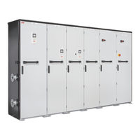
ABB ACS880-04FXT Electrical Planning Manual (50 pages)
liquid-cooled multidrive cabinets and modules
Brand:
ABB
| Category:
Industrial Equipment
| Size: 1.33 MB
Table of Contents
Table of Contents
5
Introduction to the Manual
9
Contents of this Chapter
9
Applicability
9
Safety Instructions
9
Target Audience
9
Terms and Abbreviations
10
Related Documents
11
Cabinet-Installed Multidrive Manuals
11
Multidrive Module Manuals
11
Electrical Planning Guidelines
13
Contents of this Chapter
13
Limitation of Liability
13
Selecting the Supply Disconnecting Device
13
Cabinet-Installed Multidrives
13
Multidrive Modules
13
European Union
13
North America
14
Other Regions
14
Selecting the Main Contactor (Breaker)
14
Cabinet-Installed Multidrives
14
Multidrive Modules
14
Selecting the Supply Transformer
15
Cabinet-Installed Multidrives
15
Basic Guidelines
15
Additional Notes
16
Multidrive Modules
17
IGBT Supply Modules ACS880-204LC
17
Diode Supply Modules ACS880-304LC+A019
17
Examining the Compatibility of the Motor and Drive
18
Protecting the Motor Insulation and Bearings
18
Requirements Table
18
Availability of Du/Dt Filter and Common Mode Filter by Drive or Inverter Type
21
Additional Requirements for Explosion-Safe (EX) Motors
21
And am
21
Additional Requirements for Braking Applications
21
Additional Requirements for Drives with an IGBT Supply Unit or Regenerative Rectifier Unit
21
Additional Requirements for ABB High-Output and IP23 Motors
21
Additional Requirements for Non-ABB High-Output and IP23 Motors
22
Additional Note for Sine Filters
22
Selecting the Power Cables
23
General Guidelines
23
Typical Power Cable Sizes
23
Power Cable Types
24
Recommended Power Cable Types
24
Alternate Power Cable Types
24
Not Allowed Power Cable Types
25
Power Cable Shield
25
Selecting the Control Cables
27
Shielding
27
Signals in Separate Cables
27
Signals that Can be Run in the same Cable
27
Relay Cable Type
27
Control Panel to Drive Connection
27
Routing the Cables
28
General Guidelines, IEC
28
Continuous Motor Cable Shield or Enclosure for Equipment on the Motor Cable
28
Separate Control Cable Ducts
29
Implementing Thermal Overload and Short Circuit Protections
30
Protecting the Input Power Cable against Thermal Overload
30
Diode Supply Unit
30
IGBT Supply Unit
30
Protecting the Input Power Cable in Short-Circuits
30
Protecting the Drive against Thermal Overload
30
Cabinet-Installed Multidrives
30
Multidrive Modules
30
Protecting against Short-Circuit Inside the Drive
31
Cabinet-Installed Multidrives
31
Multidrive Modules
31
Protecting the Motor and Motor Cable in Short-Circuits
31
Protecting the Motor Cables against Thermal Overload
31
Protecting the Motor against Thermal Overload
31
Implementing a Motor Temperature Sensor Connection
32
Connecting Motor Temperature Sensor to the Drive Via an Option Module
32
Connection of Motor Temperature Sensor to the Drive Via a Relay
33
Implementing a Ground Fault Protecting Function
34
Cabinet-Installed Multidrives
34
Residual Current Device Compatibility
34
Multidrives Modules
34
Implementing the Emergency Stop Function
34
Multidrive Modules
35
Implementing the Safe Torque off Function
35
Implementing the Prevention of Unexpected Start-Up Function
35
Cabinet-Installed Multidrives
35
Implementing the Safely-Limited Speed Function
35
Multidrive Modules
36
Implementing the Functions Provided by the FSO-XX Safety Functions Module
36
Cabinet-Installed Multidrives
36
Supplying Power for the Auxiliary Circuits
36
Using Power Factor Compensation Capacitors with the Drive
37
Using a Safety Switch between the Drive and the Motor
37
Implementing the Power-Loss Ride-Through Function
37
Implementing the Control of a Contactor between Drive and Motor
37
Implementing a Bypass Connection
38
Protecting the Contacts of Relay Outputs
38
Standards and Markings
41
Contents of this Chapter
41
Applicable Standards
41
Markings
42
EMC Compliance (IEC/EN 61800-3:2004 + A2012)
43
Definitions
43
Category C3
43
Category C4
43
EU Declaration of Conformity (Machinery Directive)
45
Multidrive Modules
45
Cabinet-Installed Multidrives
46
Approvals
46
Disclaimers
47
Generic Disclaimer
47
Cybersecurity Disclaimer
47
Further Information
49
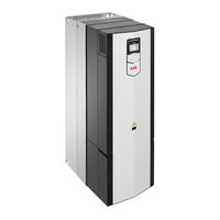
ABB ACS880-04FXT Application Manual (46 pages)
ATEX-certified Safe disconnection function, Ex II 2 GD for drives option +Q971
Brand:
ABB
| Category:
DC Drives
| Size: 1.79 MB
Table of Contents
Table of Contents
5
1 Safety Instructions
7
Contents of this Chapter
7
Use of Warnings and Notes
7
ATEX-Certified Motor Thermal Protection Functions
7
Electrical Safety Precautions
9
2 Introduction
11
Contents of this Chapter
11
Applicability
11
Target Audience
11
The ATEX-Certified Safe Disconnection Function
11
Commissioning the Drive for a Motor in a Hazardous Area
11
Compliance with the European ATEX Product Directive 2014/34/EU
12
Exclusion of Liability
12
Terms and Abbreviations
12
Related Manuals
13
3 Implementing a Motor Thermal Protection Circuit
15
Contents of this Chapter
15
Overview
15
Two-Channel Connection to Drive STO Terminals
16
General
16
Implementing the Reset of the Safety Function
16
Indications of the Safety Function
16
Connection Diagram
17
One-Channel Connection to Drive STO Terminals
18
General
18
Implementing the Reset of the Safety Function
18
Indications of the Safety Function
18
Connection Diagram
19
One-Channel or Two-Channel Connection to an FSO Module
20
General
20
Implementing the Reset of the Safety Function
20
Indications of the Safety Function
20
Connection Diagram (Two-Channel Connection)
21
Connection Diagram (One-Channel Connection)
22
Sensors
22
Protection Relays
23
Wiring
23
Insulation of the Sensor Circuit
23
General Wiring Instructions
23
4 Parameter Settings
25
Contents of this Chapter
25
Drive / Inverter
25
Switching Frequency Limitation
25
Reset Method and Status Indications
25
31.22 STO Indication Run/Stop
25
Motor Overtemperature Indication
26
31.11 Fault Reset Selection
26
Other Recommended Settings
26
FSO Module
27
General Parameters
27
Parameters for the STO Function
29
Parameters for the SSE Function
31
Parameters for the SS1 Function
31
SS1 Ramp Parameters in the Drive/Inverter Unit
33
FSE Module and Safety Pulse Encoder Parameters
33
Mechanical Brake Control
34
5 Technical Data
35
Contents of this Chapter
35
Related Standards and Directives
35
Safety Data
35
Drive/Inverter Module STO Function
35
Drive/Inverter Module STO Function and an FSO Module
36
Safety Block Diagrams
36
Response Times
37
Markings of the Drive/Inverter Module
38
ATEX Certificate
39
Declaration of Conformity
42
Further Information
45
Advertisement
Advertisement
Related Products
ABB ACS880-04F-504A-3
ABB ACS880-04F-584A-3
ABB ACS880-04F-725A-3
ABB ACS880-04F-459A-5
ABB ACS880-04F-582A-5
ABB ACS880-04F-634A-5
ABB ACS880-04F-880A-5
ABB ACS880-04F-369A-7
ABB ACS880-04F-429A-7
ABB ACS880-04F-470A-7
ABB Categories
Industrial Equipment
Controller
Measuring Instruments
Battery Charger
DC Drives
More ABB Manuals
Login
Sign In
OR
Sign in with Facebook
Sign in with Google
Upload manual
Upload from disk
Upload from URL