Sign In
Upload
Manuals
Brands
ABB Manuals
DC Drives
ACS860
User Manuals: ABB ACS860 AC Drives
Manuals and User Guides for ABB ACS860 AC Drives. We have
4
ABB ACS860 AC Drives manuals available for free PDF download: Firmware Manual, User Manual, Electrical Planning Instructions
ABB ACS860 Firmware Manual (438 pages)
primary control program
Brand:
ABB
| Category:
DC Drives
| Size: 3 MB
Table of Contents
Table of Contents
5
Introduction to the Manual
11
What this Chapter Contains
11
Applicability
11
Safety Instructions
11
Target Audience
11
Contents of the Manual
12
Related Documents
12
Terms and Abbreviations
13
Cybersecurity Disclaimer
16
Using the Control Panel
17
Control Locations and Operating Modes
19
What this Chapter Contains
19
Local Control Vs. External Control
20
Local Control
20
External Control
21
Operating Modes of the Drive
22
Speed Control Mode
23
Torque Control Mode
23
Frequency Control Mode
23
Special Control Modes
23
Program Features
25
What this Chapter Contains
25
Drive Configuration and Programming
26
Programming Via Parameters
26
Adaptive Programming
27
Control Interfaces
28
Programmable Analog Inputs
28
Programmable Analog Outputs
28
Programmable Digital Inputs and Outputs
28
Programmable Relay Outputs
28
Fieldbus Control
29
Master/Follower Functionality
30
External Controller Interface
34
Motor Control
36
Vector Control
36
Reference Ramping
36
Constant Speeds/Frequencies
37
Critical Speeds/Frequencies
37
Speed Controller Autotune
38
Oscillation Damping
41
Resonance Frequency Elimination
42
Rush Control
42
Encoder Support
43
Jogging
47
Scalar Motor Control
50
Flux Braking
51
DC Magnetization
52
Application Control
55
Application Macros
55
Motor Potentiometer
56
Mechanical Brake Control
57
DC Voltage Control
62
Overvoltage Control
62
Undervoltage Control (Power Loss Ride-Through)
62
Voltage Control and Trip Limits
63
Brake Chopper
64
Safety and Protections
65
Emergency Stop
65
Motor Thermal Protection
65
Automatic Fault Resets
68
Other Programmable Protection Functions
69
Diagnostics
71
Fault and Warning Messages, Data Logging
71
Signal Supervision
71
Maintenance Timers and Counters
71
Energy Saving Calculators
72
Load Analyzer
72
Miscellaneous
74
User Parameter Sets
74
Parameter Checksum Calculation
74
User Lock
75
Data Storage Parameters
75
Reduced Run Function
76
Du/Dt Filter Support
77
Application Macros
79
What this Chapter Contains
79
General
79
Factory Macro
80
Default Parameter Settings for the Factory Macro
80
Default Control Connections for the Factory Macro
81
Hand/Auto Macro
82
Default Parameter Settings for the Hand/Auto Macro
82
Default Control Connections for the Hand/Auto Macro
83
Torque Control Macro
84
Default Parameter Settings for the Torque Control Macro
84
Default Control Connections for the Torque Control Macro
85
Sequential Control Macro
86
Operation Diagram
86
Selection of Constant Speeds
87
Default Parameter Settings for the Sequential Control Macro
87
Default Control Connections for the Sequential Control Macro
88
Fieldbus Control Macro
89
Parameters
91
What this Chapter Contains
91
Terms and Abbreviations
92
Parameters 93 Summary of Parameter Groups
93
Summary of Parameter Groups
93
Parameter Listing
95
Actual Values
95
Input References
98
Warnings and Faults
99
Diagnostics
101
Control and Status Words
102
System Info
110
Standard DI, RO
113
Standard DIO, FI, FO
119
Standard AI
124
Standard AO
128
Operation Mode
132
Start/Stop/Direction
134
Start/Stop Mode
143
Speed Reference Selection
149
Speed Reference Ramp
157
Speed Reference Conditioning
162
Speed Control
167
Torque Reference Chain
178
Frequency Reference Chain
186
Limits
194
Fault Functions
200
Supervision
210
Generic Timer & Counter
213
Motor Thermal Protection
221
Load Analyzer
229
Mechanical Brake Control
233
Energy Efficiency
237
Monitoring/Scaling Settings
240
Data Storage
244
Panel Port Communication
247
Fieldbus Adapter (FBA)
249
FBA a Settings
253
FBA a Data in
255
FBA a Data out
255
Embedded Fieldbus
256
DDCS Communication
263
D2D and DDCS Transmit Data
270
D2D and DDCS Receive Data
274
Feedback Selection
278
Encoder Module Settings
284
Encoder 1 Configuration
285
HW Configuration
287
System
292
Motor Control
302
User Motor Parameters
304
Motor Data
305
Additional Parameter Data
311
What this Chapter Contains
311
Terms and Abbreviations
311
Parameter Groups 1
312
Parameter Groups 10
316
Speed Reference Conditioning
321
Speed Control
321
Torque Reference Chain
322
Frequency Reference Chain
323
Limits
324
Fault Functions
324
Supervision
325
Generic Timer & Counter
326
Motor Thermal Protection
327
Load Analyzer
328
Mechanical Brake Control
329
Energy Efficiency
329
Monitoring/Scaling Settings
329
Data Storage
330
Panel Port Communication
331
Fieldbus Adapter (FBA)
331
FBA a Settings
332
FBA a Data in
332
FBA a Data out
332
Embedded Fieldbus
332
DDCS Communication
333
D2D and DDCS Transmit Data
334
Feedback Selection
337
Encoder Module Settings
338
Encoder 1 Configuration
339
HW Configuration
339
System
339
Motor Control
340
User Motor Parameters
341
Fault Tracing
343
What this Chapter Contains
343
Safety
343
Indications
343
Warnings and Faults
343
Pure Events
344
Editable Messages
344
Warning/Fault History and Analysis
344
Event Logs
344
Other Data Loggers
345
Parameters that Contain Warning/Fault Information
345
QR Code Generation for Mobile Service Application
346
Warning Messages
347
Fault Messages
362
Fieldbus Control through the Embedded Fieldbus Interface (EFB)
383
What this Chapter Contains
383
System Overview
383
Connecting the Fieldbus to the Drive
384
Setting up the Embedded Fieldbus Interface
385
Setting the Drive Control Parameters
386
Basics of the Embedded Fieldbus Interface
389
Control Word and Status Word
390
References
390
Actual Values
390
Data Input/Outputs
390
Register Addressing
391
About the Control Profiles
392
The ABB Drives Profile
393
Control Word
393
Status Word
395
State Transition Diagram
396
References
397
Actual Values
398
Modbus Holding Register Addresses
399
The Transparent Profile
400
Modbus Function Codes
401
Exception Codes
402
Coils (0Xxxx Reference Set)
403
Discrete Inputs (1Xxxx Reference Set)
404
Error Code Registers (Holding Registers 400090
406
Fieldbus Control through a Fieldbus Adapter
407
What this Chapter Contains
407
System Overview
407
Basics of the Fieldbus Control Interface
409
Control Word and Status Word
410
References
410
Actual Values
411
Contents of the Fieldbus Control Word (ABB Drives Profile)
413
Contents of the Fieldbus Status Word (ABB Drives Profile)
414
The State Diagram (ABB Drives Profile)
415
Setting up the Drive for Fieldbus Control
416
Parameter Setting Example: FPBA (PROFIBUS DP)
417
Control Chain Diagrams
419
What this Chapter Contains
419
Speed Reference Source Selection I
420
Speed Reference Source Selection II
421
Speed Reference Ramping and Shaping
422
Motor Feedback Configuration
423
Load Feedback and Position Counter Configuration
424
Speed Error Calculation
425
Speed Controller
426
Torque Reference Source Selection and Modification
427
Operating Mode Selection
428
Reference Selection for Torque Controller
429
Torque Limitation
430
Torque Controller
431
Frequency Reference Selection
432
Frequency Reference Modification
433
Master/Follower Communication I (Master)
434
Master/Follower Communication II (Follower)
435
Advertisement
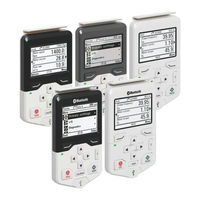
ABB ACS860 User Manual (100 pages)
Assistant control panels
Brand:
ABB
| Category:
Control Panel
| Size: 9 MB
Table of Contents
Table of Contents
5
Introduction to the Manual
11
What this Chapter Contains
11
Applicability
12
Compatibility
13
Safety
13
Intended Audience
13
Related Manuals
13
Installation and Start-Up
15
What this Chapter Contains
15
Installation
16
First Start-Up
17
Control Panel Overview
19
What this Chapter Contains
19
Display, Keys and Parts
20
Display
22
Keys
24
Left Softkey
24
Right Softkey
24
Arrow Keys
24
Help
24
Start and Stop
24
Off
25
Hand
25
Auto
25
Loc/Rem
25
Key Shortcuts
25
Control Panel and Panel Platform/Holder Leds
26
USB Connector
26
Wireless Interface
27
RJ45 Connector
27
Type Code Label on the Control Panel
27
Type Code Label on ACS-AP-I, ACS-AP-S, ACH-AP-H and ACS-BP-S Panels
27
Type Code Label on ACS-AP-W and ACH-AP-W Panels
28
Type Code Label on the Control Panel Package
29
Battery Cover
29
Basic Operation
31
What this Chapter Contains
31
User Interface Overview
31
Control Panel Navigation
32
Navigation Memory
32
Home View
33
Navigating in the Home View
33
Help
34
Common User Tasks
34
Basic Operation of the Drive
34
Parameters
35
System Information and Help
35
Faults and Warnings
35
Basic Settings and Assistants
36
Backups
36
Bluetooth Configurations
36
Functions in the Main Menu
37
What this Chapter Contains
37
Menu
38
Navigating in the Menu
39
Parameters
39
Complete List
39
By Function
39
Favorites
40
Editing the List of Favorites
40
Modified
40
Adding Parameters to the Home View
40
Editing Parameters
41
Editing Numeric Parameters
41
Editing Selection List Parameters
42
Editing Bit-Field Parameters
44
Editing Texts
44
Resetting Counters
45
Assistants
45
Launching an Assistant
45
Generating a QR Code
47
Energy Efficiency
48
Event Log
48
History Graphs
48
Trends
49
Load Profile
49
Backups
50
Creating a Parameter Backup
51
Restoring a Parameter Backup
51
System Info
52
Settings
56
Primary Settings
57
I/O
59
Diagnostics
60
Functions in the Options Menu
61
What this Chapter Contains
61
Options Menu
61
Setting the Reference
62
Editing the Contents of the Home View
62
Control of Multiple Drives
67
What this Chapter Contains
67
Connecting Multiple Drives to a Control Panel
67
Selecting Drive Menu
68
Selecting a Drive
68
Control Panel Features with Multiple Drives
69
Control Panel Views
69
The Help Page
69
Graph Data
69
Backups
69
Customized Content
69
Assistants
69
Faults and Warnings with Multiple Drives
70
Faults and Warnings in the Currently Selected Drive
70
Faults and Warnings in Other Drives
70
Fault Tracing
71
What this Chapter Contains
71
Identifying Error and Warning Messages
71
Faults
73
Warnings
73
Maintenance
75
What this Chapter Contains
75
Removing the Control Panel Cover
76
Cleaning the Control Panel
76
Cleaning the Connectors
76
Replacing the Control Panel Battery
77
Control Panel Software Updates
77
Recycling Instructions and Environmental Information
77
External Connections
79
What this Chapter Contains
79
USB Connection
79
Connecting Control Panel to PC USB
80
Connecting Drive Composer PC Tool to a Drive through the Control Panel
81
Connecting in Local Control Mode
81
Connecting in Remote Control Mode
81
Transferring Files between the Control Panel and a PC
82
Bluetooth Connection
82
Connecting Drivetune to a Drive through Bluetooth on the Control Panel
82
Installing Drivetune App on Android Device
82
Installing Drivetune App on Ios Device
82
Pairing the Drive Via Drivetune
83
Connecting Drive Composer Entry to a Drive through Bluetooth on the Control Panel
87
Technical Data
89
What this Chapter Contains
89
Connectors
89
Power Supply (from the Drive)
90
Display
90
Battery
90
Dimensions and Weight
90
Degrees of Protection
91
Materials
91
Environmental Limits
92
IEC Compliance
92
LCD Specifications
92
Bluetooth Interface
93
Bluetooth Encryption
93
Bluetooth Radio Frequency Exposure
94
Bluetooth (BT)
94
Bluetooth Low Energy (BLE)
94
FCC and Industry Canada Certifications
94
Fcc ID: 2Afngapwseries
94
IC: 20555-Apwseries
95
ANATEL Certification
95
CMIIT Certification
95
Markings
95
Disclaimers
97
Generic Disclaimer
97
Cyber Security Disclaimer
97
ABB ACS860 Electrical Planning Instructions (56 pages)
multidrives cabinets and modules
Brand:
ABB
| Category:
Industrial Equipment
| Size: 1 MB
Table of Contents
Table of Contents
5
Introduction to Manual
9
Contents of this Chapter
9
Applicability
9
Target Audience
9
Terms and Abbreviations
10
Related Documents
10
Electrical Planning Guidelines
13
Contents of this Chapter
13
Limitation of Liability
13
North America
13
Selecting the Supply Disconnecting Device
13
Cabinet-Installed Multidrives
13
Multidrive Modules
13
Selecting the Main Contactor (Breaker)
14
Cabinet-Installed Multidrives
14
Multidrive Modules
14
Selecting the Supply Transformer
14
Basic Guidelines
14
Additional Notes
15
A Drive Larger than 500 Kva with an IGBT Supply Unit or a Regenerative Rectifier Unit
15
A Drive with a 12-Pulse Diode Supply Unit
15
Two Parallel-Connected Supply Units
17
Examining the Compatibility of the Motor and Drive
17
Protecting the Motor Insulation and Bearings
17
Requirements Tables
18
Requirements for ABB Motors, P
18
100 Kw (134 Hp)
18
Requirements for ABB Motors, P
19
Requirements for Non-ABB Motors, P
20
Requirements for Non-ABB Motors, P N > 100 Kw (134 Hp)
21
Abbreviations
21
Availability of D U /D T Filter and Common Mode Filter by Drive or Inverter Type
22
Additional Requirements for Explosion-Safe (EX) Motors
22
HX_ and am
22
Additional Requirements for Braking Applications
22
Additional Requirements for Drives with an IGBT Supply Unit
22
Additional Requirements for ABB High-Output and IP23 Motors
22
Additional Requirements for Non-ABB High-Output and IP23 Motors
23
Additional Data for Calculating the Rise Time and the Peak Line-To-Line Voltage
23
Additional Note for Sine Filters
24
Protecting the Motor Insulation and Bearings
25
Requirements Tables
25
Requirements for ABB Motors, P
26
100 Kw (134 Hp)
26
Requirements for ABB Motors, P
27
100 Kw (134 Hp)
27
Requirements for Non-ABB Motors, P
28
Requirements for Non-ABB Motors, P
29
Abbreviations
29
Availability of D U /D T Filter and Common Mode Filter by Drive or Inverter Type
30
Additional Requirements for Explosion-Safe (EX) Motors
30
Additional Requirements for ABB Motors of Types Other than M2_, M3_, _XR, am
30
Am_, Nmi
30
Additional Requirements for Braking Applications
30
Voltage Boost
30
Additional Requirements for ABB High-Output and IP23 Motors
30
Additional Requirements for Non-ABB High-Output and IP23 Motors
31
Additional Data for Calculating the Rise Time and the Peak Line-To-Line Voltage
32
Additional Note for Sine Filters
33
Selecting the Power Cables
33
General Guidelines
33
Typical Power Cable Sizes
33
Power Cable Types
33
Preferred Power Cable Types
33
Alternate Power Cable Types
34
Not Allowed Power Cable Types
35
Power Cable Shield
35
Grounding Requirements
36
Additional Grounding Requirements - IEC
37
Selecting the Control Cables
37
Shielding
37
Signals in Separate Cables
37
Signals that Can be Run in the same Cable
38
Relay Cable
38
Control Panel to Drive Cable
38
PC Tool Cable
38
Routing the Cables
39
General Guidelines - IEC
39
The Motor Cable
39
Separate Control Cable Ducts
40
Implementing Thermal Overload and Short Circuit Protections
40
Protecting the Drive and Input Power Cables in Short-Circuit
40
Cabinet-Installed Multidrives
40
Multidrive Modules
40
Protecting the Motor and Motor Cable in Short-Circuits
40
Protecting the Input Power Cable against Thermal Overload
41
Cabinet-Installed Multidrives
41
Multidrive Modules
41
Protecting the Drive against Thermal Overload
41
Protecting the Motor Cables against Thermal Overload
41
Protecting the Motor against Thermal Overload
42
Protecting the Motor against Overload Without Thermal Model or Temperature Sensors
42
Implementing a Motor Temperature Sensor Connection
43
Implementing a Ground Fault Detection Function
43
Cabinet-Installed Multidrives
43
Residual Current Device Compatibility
43
Multidrives Modules
43
Implementing the Emergency Stop Function
44
Cabinet-Installed Multidrives
44
Multidrive Modules
44
Implementing the Prevention of Unexpected Start-Up Function
44
Supplying Power for the Auxiliary Circuits
44
Multidrive Modules
45
Using Power Factor Compensation Capacitors with the Drive
45
Using a Safety Switch between the Drive and the Motor
45
Implementing the Control of a Contactor between Drive and Motor
45
Implementing a Bypass Connection
46
Protecting the Contacts of Relay Outputs
46
Standards and Markings
49
Contents of this Chapter
49
Applicable Standards (Cabinets)
50
Applicable Standards (Modules)
50
Markings
50
EMC Compliance (IEC/EN 61800-3)
51
Definitions
51
Category C2
51
Category C3
52
Category C4
52
Approvals
54
Disclaimers
54
Generic Disclaimer
54
Cyber Security Disclaimer
54
Declarations of Conformity
54
Further Information
55
Advertisement
ABB ACS860 Electrical Planning Instructions (42 pages)
multidrive cabinets and modules
Brand:
ABB
| Category:
Industrial Electrical
| Size: 1 MB
Table of Contents
List of Related Manuals
2
Table of Contents
5
Introduction to the Manual
7
Contents of this Chapter
7
Purpose of this Manual
7
Applicability
7
Safety Instructions
7
Target Audience
7
Related Documents
8
Terms and Abbreviations
8
Guidelines for Planning the Electrical Installation
11
Contents of this Chapter
11
Limitation of Liability
11
Selecting the Supply Disconnecting Device
12
Selecting the Main Contactor (Breaker)
12
Selecting a Supply Transformer for a Drive Equipped with an IGBT Supply Unit or a Regenerative Rectifier Unit
13
Examining the Compatibility of the Motor
14
Protecting the Motor Insulation and Bearings
14
Requirements Table
15
Availability of Du/Dt Filter
17
Availability of Common Mode Filter
17
Additional Requirements for ABB Motors of Types Other than M2_, M3_, M4_, HX_ and
17
Additional Requirements for Braking Applications
17
Additional Requirements for Drives with an IGBT Supply Unit (ACS880-207 or -204)
17
Additional Requirements for ABB High-Output and IP23 Motors
18
Additional Requirements for Non-ABB High-Output and IP23 Motors
18
Additional Data for Calculating Rise Time and Peak Line-To-Line Voltage
19
Selecting the Power Cables
20
General Rules
20
Typical Power Cable Sizes
20
Recommended Input Power Cable Types
22
Recommended Motor Cable Types
22
Motor Cable Types for Limited Use
23
Not Allowed Motor Cable Types
23
Sufficient Conductivity of the Protective Conductor
24
Calculating the Cross-Sectional Area of the Protective Conductor
24
Sufficient Shield Conductivity to Suppress Emissions
25
Conduit
25
Armored Cable / Shielded Power Cable
25
Selecting the Control Cables
26
Shielding
26
Signals in Separate Cables
26
Signals Allowed to be Run in the same Cable
26
Relay Cable
26
Control Panel Cable Length and Type
26
Ethernet and Fieldbus Cables
26
Routing the Cables
27
Control Cable Ducts
27
Continuous Motor Cable Shield or Enclosure for Equipment on the Motor Cable
28
Implementing Thermal Overload and Short-Circuit Protection
28
Protecting the Input Power Cable in Short-Circuit Situations
28
Protecting against Short-Circuit Inside the Drive
28
Protecting the Motor and Motor Cable in Short-Circuits
28
Protecting the Drive, Motor Cable and Input Power Cable against Thermal Overload
29
Protecting the Motor against Thermal Overload
29
Protecting the Drive against Ground Faults
29
Implementing the Emergency Stop Function
30
Implementing the Prevention of Unexpected Start-Up Function
30
Implementing the Power-Loss Ride-Through Function
31
Supplying Power for the Auxiliary Circuits
31
Using Power Factor Compensation Capacitors with the Drive
32
Using a Contactor between the Drive and the Motor
33
Protecting the Contacts of Relay Outputs
34
Connecting a Motor Temperature Sensor to the Drive I/O
35
Standards and Markings
37
What this Chapter Contains
37
Applicable Standards
37
CE Marking
38
Compliance with the European Low Voltage Directive
38
Compliance with the European EMC Directive
38
Compliance with the en 61800-3:2004
38
Definitions
38
Category C3
38
Category C4
39
Compliance with the European Machinery Directive
40
Rohs Marking
40
Approvals
40
Disclaimers
40
Generic Disclaimer
40
Cyber Security Disclaimer
40
Further Information
41
Product and Service Inquiries
41
Product Training
41
Providing Feedback on ABB Drives Manuals
41
Document Library on the Internet
41
Advertisement
Related Products
ABB ACS800-37LC-0630-7
ABB ACS800-01-0001-2
ABB ACS800-U1-0070-2
ABB ACS800-U1-0050-5
ABB ACS880-07-0105A-3
ABB ACS880-07-0156A-5
ABB ACS880-07-0583A-5
ABB ACS880-01-145A-2+N5350
ABB ACS880-7207LC
ABB ACS880-04F-721A-7
ABB Categories
Industrial Equipment
Controller
Measuring Instruments
Battery Charger
DC Drives
More ABB Manuals
Login
Sign In
OR
Sign in with Facebook
Sign in with Google
Upload manual
Upload from disk
Upload from URL