Sign In
Upload
Manuals
Brands
ABB Manuals
Measuring Instruments
ACF5000
ABB ACF5000 Multi-component FTIR analyzer Manuals
Manuals and User Guides for ABB ACF5000 Multi-component FTIR analyzer. We have
2
ABB ACF5000 Multi-component FTIR analyzer manuals available for free PDF download: Manual
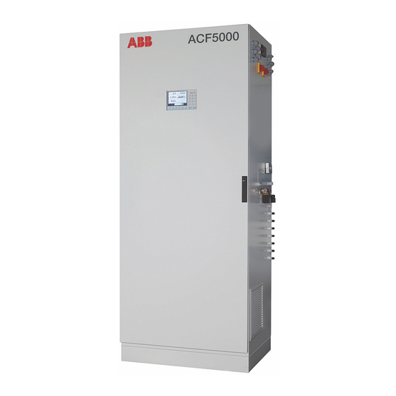
ABB ACF5000 Manual (200 pages)
Multi-component FTIR analyzer system
Brand:
ABB
| Category:
Measuring Instruments
| Size: 4 MB
Table of Contents
Table of Contents
3
Preface
6
Safety Instructions
8
Intended Use
8
Safety Instructions for Handling the Analyzer System
10
Safety Instructions for Handling the Analyzer System with Integrated FID
11
Safety Instructions for Handling the FTIR Spectrometer
12
Safety Instructions for Working with Poisonous Gases
13
Description of the Analyzer System
14
Application and Function of the Analyzer System
14
Components of the Analyzer System
16
Option "Hydrogen Monitoring of the Analyzer Cabinet
18
Preparation for Installation
20
Selection of the Sampling Point, Installation of the Wall Tube
20
Requirements for the Installation Site of the Analyzer Cabinet
22
Sample Gas Inlet Conditions
24
Operating Gases and Test Gases
25
Power Supply
27
Dimensions, Weights and Noise Level
29
Scope of Supply and Delivery
30
Material Required for the Installation (Not Supplied)
31
Installation
33
General Notices
33
Installing the Analyzer Cabinet
34
Installing the Gas Sampling Probe and Filter Unit
37
Installing the Sample Gas Line
40
Installing the Operating Gases
42
Connecting the Electrical Leads
44
Commissioning
47
Recommissioning
47
Operation
50
Display and Operation Unit
50
Display
51
Message Display
52
Status Leds
53
Numeric Keypad
54
Cancel Keys
55
Softkeys
56
Text Entry
58
Operating by Value Input
59
Operating by Key Entry
60
Password Protection
61
Blocking Operation
63
Operating the Analyzer System
64
Menu Structure
66
Display of Measured Value
67
Adjustment: Basics
68
Controlling the Adjustment
68
Manual Adjustment
69
Automatic Adjustment
70
Adjustment Methods
72
FID: Conversion of Concentration Data
74
Adjustment: Configuration
76
Configuring the Automatic Reference FTIR
76
Automatic Adjustment Check (AAC): Configuring the Time Sequence
78
Automatic Adjustment Check (AAC): Settings and Export of the QAL3 Data
80
Configuring the Automatic Drift Check (ADC)
83
Configuring Manual Adjustment
85
Configuring Automatic Adjustment of the FID
86
Configuring Automatic Adjustment of the Oxygen Sensor
88
Check Time Conflicts of the Automatic Processes
90
Output Current Response
91
Adjustment: Operation
92
Carrying out Manual Reference
92
Start Automatic Adjustment Check (AAC) Manually
98
Carry out Manual Adjustment
100
Manual Start of Automatic Adjustment
101
Configuration: Component Functions
102
Configuring Measuring Range
102
Configuring Automatic Measuring Range Switching
107
Configuring Filter
108
Active Component Selection
109
Configuring Limit Monitoring
110
Configuring FTIR Limit Monitoring
111
Configuring Dry Base and O
112
Reference
112
Changing Module Name
113
Configuration: System Functions
114
Setting Time Zone, Date and Time
114
Selecting User Interface Language
115
Change Password
116
Blocking Operation
117
Setting System Modules
118
Add System Module
120
Replace System Module
121
Delete System Module
122
Save Configuration
123
Configuring Status Signals
124
Configuring Ethernet Connection
125
Configuring Modbus Connection
126
Configuring Profibus
127
Configuring Bus I/Os
128
Configuration: Display Functions
129
Display Features
129
Display Overview
131
Page Overview
132
Parameter Overview
133
User Page Configuration
134
Moving a Display Element from One Page to Another
135
Moving a Display Element Within a Page
136
Configuring the Bar Display or Point Display
137
Value Input
138
Configuring Value Input
139
Key Entry
140
Configuring Key Entries
141
Maintenance
142
General Notices
142
Visual Inspection
143
Cleaning the Analyzer Cabinet
144
Seal Integrity Test
145
FID: Seal Integrity and Functional Checks
147
Maintenance Switch
149
Emergency Purging
150
Monitoring the Internal Cabinet Temperature
151
Connecting Gas Paths and Inserting Validation Cells
152
Changing Analog Output Current Range
153
Adjustment Reset
154
Basic Adjustment
155
FID: Standby/Restart
156
Configuring Saving of FTIR Spectral Data
158
Configuring Automatic Back-Purging of the Gas Extraction Probe
159
Replacing Wearing Parts
161
Replacing Filter on the Gas Sampling Probe
162
Replacing Sample Gas Filter in the ASP Block
164
Replacing Filter in the Compressed Air Main Regulator (-J85)
166
Replacing Filters in the Sample Gas Pressure Regulator
167
Replacing Filter Cells in Air Purifier AU5
168
Replacing Filter Pad in the Fan
169
Replacing the Battery on the System Controller
170
Replacing Pressure Equalization Screws
171
Status Messages, Troubleshooting
172
Dynamic QR Code
172
Process Status
174
System Status: Status Messages
175
System Status: Status Signals
176
Status Message Categories
177
Status Message System
179
Status Messages FTIR
187
Analyzer System: Troubleshooting
191
FID: Troubleshooting
192
Notify Service
194
Decommissioning
195
Shutting down the Analyzer System
195
Packing the Analyzer Cabinet
195
Disposal
196
Index
197
Advertisement
ABB ACF5000 Manual (164 pages)
Multi-component FTIR emission monitoring system
Brand:
ABB
| Category:
Industrial Equipment
| Size: 9 MB
Table of Contents
Table of Contents
2
Safety
4
General Information and Instructions
4
System Documentation
4
Further Documents
4
Warnings
4
Warranty Provisions
5
Intended Use
5
Improper Use
5
Safety Instructions
6
National Regulations
6
Potential Equalization
6
Safety Instructions for the Control Cabinet Fan
7
General Information
7
Requirements for Operation
7
Warranty
7
Safety Instructions for the Control Cabinet Cooling Unit
8
Safety Instructions for the FID Analyzer Module
8
Safety Instructions for the FTIR Spectrometer Module
10
Electric Safety
10
Laser Safety
10
Cyber Security Disclaimer
11
Software Downloads
11
Services and Ports on the Ethernet Interface
11
Manufacturer's Address
11
Service Address
11
Design and Function
12
Area of Application and Function of the Analyzer System
12
Functional Description
12
Design
13
Air Purifier
14
Hydrogen Monitoring of the Analyzer Cabinet (Optional)
15
Product Identification
16
Name Plate
16
Plates and Symbols
17
Scope of Delivery
19
Transport and Storage
20
Safety Instructions
20
Inspection
20
Transporting the Device
20
Storing the Device
20
Packaging
21
Returning Devices
21
Preparation for Installation
22
Selection of the Sample Gas Extraction Point and Installation of the Conduit Pipe
22
Requirements for the Installation Site
24
Installation Location
25
Dimensions, Weights and Noise Level
25
Power Supply
26
Safety
27
Material Required for Installation
27
Sample Gas Inlet Conditions
28
Corrosive Gases
28
Operating Gases and Test Gases
29
Instrument Air
30
Installation
31
Safety Instructions
31
General Notes
31
Installing the Analyzer Cabinet
32
Installing the Gas Sampling Probe and Filter Unit
34
Installing the Sample Gas Line
36
Operating Gases and Test Gases
38
Electrical Connections
40
Digital Inputs
40
Commissioning
42
Safety Instructions
42
Initial Commissioning
42
Recommissioning
42
Start of the Measurement
43
FID Recommissioning
43
Igniting the Flame
44
Operation
45
General
45
LCD-Indicator
47
Status Leds
48
Numeric Keypad
49
Entering Text
50
Selecting and Changing Parameters
51
Value Input
51
Password Protection
52
Factory Setting
53
Change Password
53
Menu Structure
54
Process Display
55
Adjusting the Analyzer System
56
Principles
56
Adjustment Methods
58
FID - Conversion of Concentration Data
60
Configuration
62
Adjustment Method
71
Automatic Adjustment
82
Configuration
83
Sample Component Functions
83
Configure Filter
86
Standard Configuration
87
System Functions
90
Daylight Saving Time
90
Analog Outputs
96
Digital Communication
97
LCD Display
103
Display Features
103
Display Elements
103
Display Overview
104
Page Overview
105
Parameter Overview
106
Key Entry
111
Diagnosis / Troubleshooting
113
Safety Instructions
113
The Dynamic QR Code
113
Process and Device Status
115
Status Message Categories
117
Possible Status Messages
119
Possible Status Messages - FTIR
127
Troubleshooting
131
FID - Troubleshooting
132
Temperature Problem
132
Zero Drift
132
Notify Service
133
Returning Devices
134
Maintenance
135
Safety Instructions
135
Visual Inspection
136
Cleaning the Analyzer Cabinet
137
Seal Integrity Test
137
FID - Leak and Function Tests
138
Maintenance Switch
140
Emergency Purging
141
Monitoring the Internal Cabinet Temperature
141
Connecting Gas Paths and Inserting Validation Cells
142
Adjustment Reset
143
Basic Adjustment
143
FID - Standby / Restart
144
Configure Saving of FTIR Spectra
145
Configure Automatic Back-Purging of the Gas Extraction Probe
146
Replacement of Wear Parts
148
Spare Part Information
148
Replacing Filter on the Gas Sampling Probe
149
Replacing Sample Gas Filter in the ASP Block
150
Wearing Parts
150
Removing the Filter
151
Replacing Filter in the Compressed Air Main Regulator (-J85)
152
Replacing the Filter Element
152
Replacing Filters in the Sample Gas Pressure Controller
153
Replace Filter Cartridges in Air Purifier AU5
154
Replacing Filter Pad in the Fan
155
Replacing the System Controller Battery
155
Replace Pressure Equalization Screws
156
Decommissioning
157
Safety Instructions
157
Shutting down the Analyzer System
157
Packaging the Analyzer System
158
Recycling and Disposal
159
Specification
159
Appendix
160
Return Form
160
Advertisement
Related Products
ABB ACF-NT
ABB ACX
ABB AX416
ABB AX430
ABB AX411
ABB AX456
ABB A43
ABB A44
ABB AX400 Series
ABB AK101
ABB Categories
Industrial Equipment
Controller
Measuring Instruments
Battery Charger
DC Drives
More ABB Manuals
Login
Sign In
OR
Sign in with Facebook
Sign in with Google
Upload manual
Upload from disk
Upload from URL