Sign In
Upload
Manuals
Brands
ABB Manuals
Transmitter
266 HART Series
ABB 266 HART Series Manuals
Manuals and User Guides for ABB 266 HART Series. We have
2
ABB 266 HART Series manuals available for free PDF download: Operating Instruction
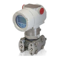
ABB 266 HART Series Operating Instruction (80 pages)
2600T Series Pressure Transmitters Engineered solutions for all applications
Brand:
ABB
| Category:
Transmitter
| Size: 8.01 MB
Table of Contents
Table of Contents
2
Introduction
4
Instruction Manual Structrure
4
Models Covered by this Manual
4
Worlwide Service Support Centers
4
Product Description
4
Safety Notes
5
General Safety Information
5
Improper Use
6
Technical Lomit Values
6
Warranty Prevision
6
Plates and Symbols
6
Operator Liability
7
Qualified Personnel
7
Returning Devices
7
Disposal
7
Information on WEEE Directive
7
Transport and Storage
7
Safety Information for Electrical Installation
7
Saferty Information for Inspection and Maintenance
8
Transmitter Overview
9
Transmitter Components Overview
9
Range and Span Consideration
10
Opening the Box
10
Packaging Content
10
Identification
10
Optional Wired-On SST Plate (I1)
11
Handling
11
Storage
11
Mounting
12
General
12
IP Protection and Designation
12
Mounting the Transmitter
12
Transmitter Factory Configuration Consideration
12
Hazardous Area Consideration
13
Pressure Equipment Directive (PED) (97/23/CE)
13
Devices with PS >200 Bar
13
Mounting a Differential Pressure Sensor Transmitter
13
Bracket Mounting
14
B2 Pipe and Wall Mounting Bracket Details
18
B5 Flat Type Bracket Details
19
Mounting a P Style Pressure Transmitter
19
B1 and B2 Barrel Housing Bracket Details
20
B2 DIN Housing Bracket Details
21
Transmitter Housing Rotation
22
Integral Display Rotation
22
Impulse Piping Connection for Standard Instruments
22
Process Connection Considerations
23
Kynar Inserts Connection
23
Installation Recommandations
24
Transmitter Wiring
28
Cable Connection
28
Analogue Output (HART) Transmitter Wiring
29
Supply Requirement
29
Wiring Procedure
30
Electrical Connection Via Connectors
30
Grounding
31
Protective Grounding
31
Integrated Lightening Protection
31
Commissioning
32
Analogue and HART Communication Models
32
Standard Setting for Normal Operation
32
Standard Setting for Error Detection (Alarm)
32
Write Protect
33
Correcting the Lower Range Value / Zero Shift
33
Set Lower Range Value
33
Correct the Zero Shift
33
Installing/Removing the External Pushbuttons
34
Installing/Removing the LCD Display
34
Securing the Housing Cover in Flameproof Areas
34
Operation
34
Local Pushbuttons Functionality
34
Factory Settings
35
Configuration Types
35
Configuring the Transmitter Without an Integral LCD HMI
35
LRV an URV Configuration
35
Correction of Zero Shift (Zero Bias / Offset)
36
Configuration of the Pressure Transmitter Using LCD HMI
36
LCD (L1) Activation Considerations
37
LCD (L5) Activation Considerations
37
Activation Procedure for TTG (L5) and LCD (L1)
37
HMI Menu Structure
37
Easy Set-Up
39
Device Set-Up
40
Display
44
Process Alarm
47
Calibrate
48
Totalizer
49
Diagnostics
52
Device Info
53
Communication
54
Damping
55
Transfer Function
55
Transfer Functions Description
55
Linear
55
Square Root
55
Square Root to the 3Rd Power
56
Square Root to the 5Th Power
56
Custom Linearization Curve
56
Bidirectional Flow
57
Cylindric Lying Tank
57
Spherical Tank
57
Configuration with the PC / Laptop or HHT
57
Configuration with Graphical User Interface
59
Error Messages
59
LCD Display
59
Error States and Alarms
60
Error List
60
Maintenance
63
Returns and Removal
63
Pressure Transmitter Sensor
63
Removing/Installing the Process Flanges
64
Pressure Transducer Replacement
65
Hazardous Area Consideration
66
Ex Safety Aspects and IP Protection (Europe)
66
Entities for L5 Optional Integral LCD Display
70
Ex Safety Aspects and IP Protection (North America)
70
Additional Instruction for IEC 61508 Certified Device
71
Safety Philosophy
71
Application
71
Physical Environment
71
Role and Responsibilities
71
Management of Functional Safety
71
Information Requirements
71
Overall Safety Life-Cycle Information
71
Applicable Laws and Standards
71
System Safety Requirement Assignment
72
System Structure
72
Safety Requirement Allocation
72
Safety Routines
72
Commissioning
72
Overall System Functionality
72
Faults Outside the Functional Safety
72
Other Consideration
72
Architecture Description and Principle of Operation
73
Principle of Operation
73
Commissioning and Configuration Issues
73
Operating Mode Enabling and Disabling
73
Proof Tests
73
Safety-Related Parameters
74
Trouble Sheet
75
Control of Substances Hazardous to Health (C.O.S.H.H.)
76
EC Declaration of Conformity
77
Advertisement
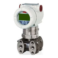
ABB 266 HART Series Operating Instruction (76 pages)
Pressure transmitters
Brand:
ABB
| Category:
Transmitter
| Size: 14.07 MB
Table of Contents
Table of Contents
3
1 Introduction
5
Instruction Manual Structure
5
Models Covered by this Manual
5
Product Description
5
2 Safety
6
General Safety Information
6
Improper Use
6
Technical Limit Values
6
Warranty Provision
6
Use of Instruction
6
Operator Liability
7
Qualified Personnel
7
Returning Devices
7
Disposal
7
Information on WEEE Directive 2012/19/UE (Waste Electrical and Electronic Equipment)
7
Transport and Storage
7
Safety Information for Electrical Installation
7
Safety Information for Inspection and Maintenance
7
3 Transmitter Overview
8
Transmitter Components Overview
8
Range & Span Consideration
9
4 Opening the Box
10
Identification
10
Optional Wired-On SST Plate (I1)
11
Handling
11
Storage
11
5 Mounting
12
General
12
IP Protection & Designation
12
Mounting the Transmitter
12
Transmitter Factory Configuration Consideration
12
Hazardous Area Considerations
12
Pressure Equipment Directive (PED) (2014/68/EU)
13
Devices with PS >200
13
Devices with PS ≤200 Bar
13
Mounting a DP Sensor Transmitter (266DSH/266MST/ 266RST/266DRH/266MRT/266RRT)
13
Bracket Mounting (Optional)
14
B2 Pipe and Wall Mounting Bracket Details
17
B5 Flat Type Bracket Details
18
Mounting a P Style Pressure Transmitter
19
B6 and B7 Barrel Housing Bracket Details
21
B7 DIN Housing Bracket Details
22
Transmitter Housing Rotation
23
Integral Display Rotation
23
Display Removal
23
Impulse Piping Connection for Standard Instruments
23
Process Connections Considerations
24
Kynar Inserts Connection
24
Screw Torques for Models with Kynar Inserts
24
Installation Recommendations
25
Steam or Clean Liquids Flow Measurement
25
Gas or Liquid Flow Measurement
25
Liquid Level on Closed Tanks (Dry Leg)
26
Liquid Level on Closed Tanks (Wet Leg)
26
Liquid Level Measurement with Open Tanks
26
Pressure Measurement on a Tank
27
Pressure Measurement of a Liquid in a Pipe
27
Pressure Measurement of a Vapor in a Pipe
28
Pressure Measurement of a Gas in a Pipe
28
6 Transmitter Wiring
29
Cable Connection
29
Analogue Output (HART) Transmitter Wiring
29
Supply Requirement
30
Wiring Procedure
30
Electrical Connection Via Connectors
30
Harting Connector on DIN Housing
30
Assembling and Connecting the Socket Connector
31
Grounding
31
Surge Protector Equipped Terminal Block (Optional)
31
Common Mode Voltages
31
7 Commissioning
32
Analogue and HART Communication Models
32
Standard Setting for Normal Operation 3.8 Ma / 20.5 Ma
32
Standard Setting for Error Detection (Alarm) 3.7 Ma / 21 Ma
32
Write Protection
32
Write Protection Activation Via External Push Button
32
Write Protection Activation Via Dip Switch
33
Correcting the Lower Range Value / Zero Shift
33
Set Lower Range Value
33
Correct the Zero Shift
33
Installing/Removing the External Push Buttons (Option R1)
33
Local Display
34
Installing/Removing the LCD Display
34
Securing the Housing Cover in Flameproof Areas
34
8 Operation
35
Local Push Buttons Functionality (Option R1)
35
Factory Settings
35
Configuration Types
35
Configuring the Transmitter Without an LCD HMI
35
LRV and URV Configuration (4
35
HMI as Feedback of the Local Push Button Operations
36
Correction of Zero Shift with PV Zero Bias / Offset
36
Hardware Settings
36
Advanced HART
36
Standard HART
37
Configuration Using the LCD HMI with Keypad
37
LCD (L1 and LS Option) Activation Considerations
38
Through the Glass (TTG) (L5 Option) Activation
38
Activation Procedure for Lcds
38
HMI Menu Structure
38
Easy Set-Up -Standard HART Version
40
Device Set-Up
42
Display
46
Process Alarm
49
Calibrate
50
Totalizer
51
Diagnostics
54
Device Info
55
Communication
56
Damping (DAMPING)
57
Transfer Function
57
Linear
57
Square Root
57
Square Root to the 3Rd Power
58
Square Root to the 5Th Power
58
Custom Linearization Curve
58
Bidirectional Flow
58
Is Connected to a Bidirectional Flow Element)
58
Cylindric Lying Tank
59
Spherical Tank
59
Configuration with Pc/Laptop or Handheld Terminal
59
Configuration with Graphical User Interface (DTM)
60
Standard and Advanced HART: Functionality
60
Advanced HART Software Revision History
60
Standard HART Software Revision History
60
9 Error Messages
61
LCD Display
61
Error States and Alarms
61
10 Maintenance
64
Returns and Removal
64
Pressure Transmitter Sensor
64
Removing/Installing the Process Flanges
64
Pressure Transducer Replacement
65
Electronic Replacement
65
Electronic Upgrade from Standard to Advanced HART
65
11 Hazardous Area Considerations
66
Ex Safety Aspects and IP Protection (Europe)
66
Entities for "L5" Option Display with TTG Technology)
70
Ex Safety Aspects and IP Protection (North America)
70
Applicable Standards
70
Classifications
70
Customer Support
73
Advertisement
Related Products
ABB 266HSH
ABB 266H Series
ABB 266FF
ABB 266CRH
ABB 266CR Series
ABB 266JR Series
ABB 266JST
ABB 266Dx
ABB 266DSH
ABB 266VSH
ABB Categories
Industrial Equipment
Controller
Measuring Instruments
Battery Charger
DC Drives
More ABB Manuals
Login
Sign In
OR
Sign in with Facebook
Sign in with Google
Upload manual
Upload from disk
Upload from URL