Sign In
Upload
Manuals
Brands
abaco systems Manuals
PCI Card
PCI-5565PIORC
abaco systems PCI-5565PIORC Manuals
Manuals and User Guides for abaco systems PCI-5565PIORC. We have
1
abaco systems PCI-5565PIORC manual available for free PDF download: Hardware Reference Manual
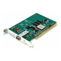
abaco systems PCI-5565PIORC Hardware Reference Manual (66 pages)
Ultrahigh Speed FiberOptic Reflective Memory with Interrupts
Brand:
abaco systems
| Category:
PCI Card
| Size: 0 MB
Table of Contents
Figure 1 Block Diagram of PCI-5565PIORC
8
Figure 2 Typical Reflective Memory Network
9
Table of Contents
13
Handling and Installation
17
Unpacking Procedures
17
Handling Precaution
17
Switch S1 and S2 Configuration
18
Before Installation Switch S1 and S2 Configuration
18
Table 1-1 Example Node ID Switch S2 RFM-5565
19
Table 1-2 Switch S1 Configuration RFM-5565
19
Table 1-3 S1 Memory Size
19
Figure 1-1 S1 and S2 Location PCI-5565PIORC
20
Physical Installation
21
Figure 1-2 Installing the PCI-5565PIORC
21
Front Panel Description
22
Figure 1-3 Front Panel of PCI-5565PIORC
22
LED Description
23
Cable Configuration
23
Connector Specification (Singlemode and Multimode)
23
Table 1-4 LED Descriptions
23
Table 1-5 Cable Specifications for Multimode and Singlemode
23
Figure 1-4 LC Type Fiber-Optic Cable Connector
24
Figure 1-5 Example: Six Node Ring Connectivity PCI-5565PIORC
24
Theory of Operation
25
Basic Operation
25
Front Bezel LED Indicators
25
RFM-5565 Register Sets
26
Reflective Memory RAM
26
Interrupt Circuits
27
Figure 2-1 Interrupt Circuitry Block Diagram
28
Network Interrupts
29
Redundant Transfer Mode of Operation
29
Rogue Packet Removal Operation
30
Programming
31
PCI Configuration Registers
32
Table 3-1 PCI Configuration Registers
32
Table 3-2 PCI Configuration ID Registers
32
Table 3-3 PCI Command Register
33
Table 3-4 PCI Status Register
34
Table 3-5 PCI Revision ID Register
35
Table 3-6 PCI Class Code Register
35
Table 3-7 PCI Cache Line Size Register
35
Table 3-8 PCI Latency Timer Register
35
Table 3-9 PCI Header Type Register
35
Table 3-10 PCI Built-In Self Test Register
36
Table 3-11 PCI Base Address Register 0 for Access to Local Configuration Registers
36
Table 3-12 PCI Base Address Register 1 for Access to Local Configuration Registers
37
Table 3-13 PCI Base Address Register 2 for Access to RFM Control and Status Registers
37
Table 3-14 PCI Base Address Register 3 for Access to Reflective Memory
38
Table 3-15 PCI Base Address Register 4
38
Table 3-16 PCI Base Address Register 5
39
Table 3-17 PCI Cardbus CIS Pointer Register
39
Table 3-18 PCI Subsystem Vendor ID Register
39
Table 3-19 PCI Subsystem ID Register
39
Table 3-20 PCI Expansion ROM Base Register
39
Table 3-21 PCI Capability Pointer Register
40
Table 3-22 PCI Interrupt Line
40
Table 3-23 PCI Interrupt Pin
40
Table 3-24 PCI Min_Gnt
40
Table 3-25 PCI Max_Lat
40
Local Configuration Registers
41
Table 3-26 Local Configuration and DMA Control Registers
41
Table 3-27 Mode/Dma Arbitration Register
42
Table 3-28 Big/Little Endian Descriptor Register
42
Table 3-29 Interrupt Control and Status Register
43
Table 3-30 INTCSR Interrupt Enables
43
Table 3-31 INTCSR Interrupt Status
44
Table 3-32 PCI Core/Features Revision ID
44
Table 3-33 DMA Channel 0 Mode Register
44
Table 3-34 DMA Channel 0 PCI Address Register
44
Table 3-35 DMA Channel 0 Local Address Register
45
Table 3-36 DMA Channel 0 Transfer Size (Bytes) Register
45
Table 3-37 DMA Channel 0 Descriptor Pointer Register
45
Table 3-38 DMA Channel 0 Command/Status Register
45
Table 3-39 DMA Channel 0 PCI Dual Address Cycles Upper Address
46
Table 3-40 PCI PIO Direct Slave Local Address Range
46
Table 3-41 PCI PIO Direct Slave Local Base Address (Remap)
46
RFM Control and Status Registers
48
Table 3-42 Memory Map of the Local Control and Status Registers
48
Board Revision Register
49
Board ID Register
49
Board Revision Build Register
49
Node ID Register
49
Local Control and Status Register 1
49
Table 3-43 Local Control and Status Register 1
49
Table 3-44 PCI PIO Window Sizes
51
Table 3-45 Config 1 and Config 0 Memory Size
51
Table 3-46 Offset 1 and Offset 0
52
Local Interrupt Control Registers
53
Table 3-47 Local Interrupt Status Register
53
Network Target Data Register
56
Network Target Node Register
56
Network Interrupt Command Register
56
Table 3-48 Local Interrupt Enable Register
56
Interrupt 1 Sender Data FIFO
57
Interrupt 1 Sender ID FIFO
57
Interrupt 2 Sender Data FIFO
57
Table 3-49 Network Interrupt Command Register
57
Interrupt 2 Sender ID FIFO
58
Interrupt 3 Sender Data FIFO
58
Interrupt 3 Sender ID FIFO
58
Interrupt 4 Sender Data FIFO
58
Interrupt 4 Sender ID FIFO
58
Figure 3-1 Block Diagram of the Network Interrupt Reception Circuitry
59
Example of a Block DMA Operation for RFM-5565
60
Table 3-50 DMA Registers
60
Example of a Scatter-Gather DMA Operation for RFM-5565
61
Table 3-51 DMA Channel 0 Mode Settings
62
Example of a PCI PIO Sliding Window Operation for RFM-5565
63
Table 3-52 PCI PIO Window Selections
63
Example of Network Interrupt Handling
65
Setup
65
Servicing Network Interrupts
65
Advertisement
Advertisement
Related Products
abaco systems PPC11A
abaco systems PEX430
abaco systems PMC423
abaco systems Categories
Motherboard
Single board computers
Computer Hardware
Adapter
PCI Card
More abaco systems Manuals
Login
Sign In
OR
Sign in with Facebook
Sign in with Google
Upload manual
Upload from disk
Upload from URL