Sign In
Upload
Manuals
Brands
AAON Manuals
Controller
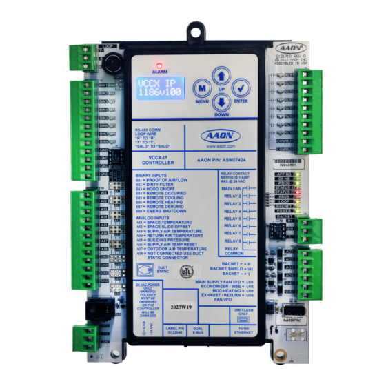
VCCX-IP
AAON VCCX-IP HVAC Controller Manuals
Manuals and User Guides for AAON VCCX-IP HVAC Controller. We have
1
AAON VCCX-IP HVAC Controller manual available for free PDF download: Technical Manual
AAON VCCX-IP Technical Manual (96 pages)
Brand:
AAON
| Category:
Controller
| Size: 13 MB
Table of Contents
Table of Contents
3
Table of Figures
5
Table of Tables
6
Overview
7
Features
7
Applications
8
Part Number Cross Reference
9
VCCX-IP Controller Components
11
Figure 1: VCCX-IP Controller Components
11
Dimensions
12
VCCX-IP Controller
12
Figure 2: VCCX-IP Controller Dimensions
12
VCC-X EM1 Expansion Module
13
Figure 3: VCC-X EM1 Expansion Module Dimensions
13
12 Relay E-BUS Module
14
Relay E-BUS Module Dimensions
14
Wiring
15
Important Wiring Considerations
15
Table 1: Voltage and Environment Requirements
15
VCCX-IP Controller
16
Figure 5: VCCX-IP Controller Input Wiring
16
Figure 6: VCCX-IP Controller Output Wiring
17
VCC-X EM1 Expansion Module
18
Figure 7: Entering Water Temperature Sensor, Return Air Plenum Pressure and Return/Exhaust Proof of Flow
18
Figure 8: Direct Fire Wiring
18
Figure 9: VCC-X EM1 Exhaust Duct Static Pressure and Economizer Actuator Feedback Wiring
19
Figure 10: VCC-X EM1 Expansion Module Output Wiring
20
12 Relay E-BUS Expansion Module
21
Airflow Station
22
Figure 12: EBTRON GTC116 or HTN104 Series, Greentrol GA-200-N Series, and Paragon Microtranseq Series Airflow Measurement Digital Transmitter Wiring
22
Start-Up and Commissioning
23
Powering up and Configuration
23
Figure 13: Operator Interfaces
23
Inputs and Outputs
24
VCCX-IP Controller and EM1 Module Inputs/Outputs Maps
24
Table 2: VCCX-IP Controller Analog Inputs
24
Table 3: VCCX-IP Controller Binary Inputs
24
Table 4: VCCX-IP Controller Analog Outputs
24
Table 5: VCCX-IP Controller Relay Outputs
24
Table 6: VCC-X EM1 Expansion Module Analog Inputs
25
Table 7: VCC-X EM1 Expansion Module Binary Inputs
25
Table 8: VCC-X EM1 Expansion Module Analog Outputs
25
Table 9: VCC-X EM1 Expansion Module Relay Outputs
25
VCCX-IP Controller Inputs/Outputs Descriptions
26
VCC-X EM1 Expansion Module Inputs/Outputs Descriptions
28
User Configurable Relay Outputs
29
Table 10: User-Configurable Relay Outputs
29
Sequence of Operations
30
Configuration Options
30
Modes of Operation
32
Alarms
47
Figure 14: Prism 2 ALARM Button
47
Figure 15: Prism 2 ALARM Menu
47
Figure 16: Prism 2 Direct Fire Alarms Screen
49
Figure 17: Prism 2 Compressor Alarms Screen
50
Figure 18: Prism 2 EVAP Module Alarms Screen
50
Trend Logs
51
Table 11: VCCX-IP Controller Trend Logs
51
Table 12: RSMZ Module Trend Log
51
Table 13: RSMV/RSMD Module Trend Logs
52
Table 14: RSMZ Trend Log Enumerated Values
52
Table 15: RSMZ Module Comp Status Trend Log
53
Table 16: RSMZ Module RSM Alarm Trend Log
53
Table 17: RSMZ Module VFD Status Trend Log
53
Table 18: VCCX-IP Trend Log Bit Strings
55
Table 19: VCCX-IP Trend Log Bit Strings (Continued)
56
Updating Via USB
57
LED Diagnostics
58
Figure 19: VCCX-IP Controller LED Locations
59
Figure 20: VCC-X EM1 Expansion Module LED Locations
59
Temperature Sensor Testing
60
Table 20: 0-5V Temperature Sensor - Voltage and Resistance for Type III Sensors
60
Pressure Sensor Testing
61
Table 21: Duct Static Pressure/Voltage for Duct Static Pressure Sensors
61
Table 22: Building Static Pressure/Voltage for Building Pressure Sensors
61
Appendix A: System Configuration
62
Options
62
Stand-Alone System Layout
63
Figure 21: Typical Stand-Alone System Layout
63
Networked System Single Loop Layout
64
Figure 22: Typical Networked Single Loop System Layout
64
Networked System Multiple Loop Layouts
65
Figure 23: Typical Networked Multiple Loop System Layout
65
Appendix B: Lcd Screens
66
LCD Display Screen and Navigation Keys
66
Figure 24: LCD Display and Navigation Keys
66
Table 23: Navigation Key Functions
66
Table 24: Editing Key Functions
66
Main Screens Map
67
Screen Descriptions
68
Table 25: Main Screens
68
Table 26: Controller Screens
68
Table 27: Settings Screens - BAC Type MSTP
69
Table 28: Settings Screens - BAC Type IP
69
Table 29: Status Screens
70
Table 30: Alarms Screens
71
Table 31: Output Override Screens
72
Table 32: Air Balance Screens
72
Appendix C: Bacnet Guide
73
Bacnet Connection to MS/TP or IP Network
73
Figure 25: VCCX-IP Bacnet Connection to MS/TP or IP Network
73
Analog Inputs
74
Analog Values
82
Binary Inputs
88
Enumerated Fields
92
Table 33: VCCX Control Mode = Enumerated
92
Table 34: VCCX Control Status = Enumerated
92
Table 35: VCCX Mode Status = Enumerated
92
Bitfields
93
Table 36: RSMZ Warnings Status Bit Strings
93
Table 37: RSMZ Faults Status Bit Strings
93
Table 38: RSMZ Lockout Status Bit Strings
93
Table 39: RSMZ Drive Status Bit Strings
93
Table 40: RSMZ Module VFD1 Alarm Trend Log
94
Table 41: RSMZ Module VFD2 Alarm Trend Log
94
Bacnet Protocol Implementation Conformance Statement - VCCX-IP
95
Advertisement
Advertisement
Related Products
AAON Orion VCCX2
AAON VCCX-454
AAON V07150
AAON V12100 MHGRV-X
AAON V82790
AAON V3-C
AAON V3-E
AAON V3-D
AAON V3 Series
AAON V3-B
AAON Categories
Controller
Control Unit
Air Handlers
Heat Pump
Air Conditioner
More AAON Manuals
Login
Sign In
OR
Sign in with Facebook
Sign in with Google
Upload manual
Upload from disk
Upload from URL