Table of Contents
Advertisement
Copyright
This publication, including all photographs, illustrations and software, is protected
under international copyright laws, with all rights reserved. Neither this manual, nor
any of the material contained herein, may be reproduced without written consent of
the author.
Version 1.0A
Disclaimer
The information in this document is subject to change without notice. The manufac-
turer makes no representations or warranties with respect to the contents hereof and
specifically disclaims any implied warranties of merchantability or fitness for any
particular purpose. The manufacturer reserves the right to revise this publication and
to make changes from time to time in the content hereof without obligation of the
manufacturer to notify any person of such revision or changes.
Trademark Recognition
Microsoft, MS-DOS and Windows are registered trademarks of Microsoft Corp.
AMD, Phenom, Athlon, Sempron and Duron are registered trademarks of AMD
Corporation.
Other product names used in this manual are the properties of their respective
owners and are acknowledged.
Federal Communications Commission (FCC)
This equipment has been tested and found to comply with the limits for a Class B
digital device, pursuant to Part 15 of the FCC Rules. These limits are designed to
provide reasonable protection against harmful interference in a residential installa-
tion. This equipment generates, uses, and can radiate radio frequency energy and, if
not installed and used in accordance with the instructions, may cause harmful inter-
ference to radio communications. However, there is no guarantee that interference
will not occur in a particular installation. If this equipment does cause harmful
interference to radio or television reception, which can be determined by turning the
equipment off and on, the user is encouraged to try to correct the interference by one
or more of the following measures:
•
Reorient or relocate the receiving antenna
•
Increase the separation between the equipment and the receiver
•
Connect the equipment onto an outlet on a circuit different from that to
which the receiver is connected
•
Consult the dealer or an experienced radio/TV technician for help
Shielded interconnect cables and a shielded AC power cable must be employed with
this equipment to ensure compliance with the pertinent RF emission limits govern-
ing this device. Changes or modifications not expressly approved by the system's
manufacturer could void the user's authority to operate the equipment.
Preface
Preface
Advertisement
Table of Contents

Related Manuals for ECS HDC-M


Summary of Contents for ECS HDC-M
- Page 1 Preface Copyright This publication, including all photographs, illustrations and software, is protected under international copyright laws, with all rights reserved. Neither this manual, nor any of the material contained herein, may be reproduced without written consent of the author. Version 1.0A Disclaimer The information in this document is subject to change without notice.
-
Page 2: Declaration Of Conformity
Declaration of Conformity This device complies with part 15 of the FCC rules. Operation is subject to the following conditions: • This device may not cause harmful interference • This device must accept any interference received, including interfer- ence that may cause undesired operation Canadian Department of Communications This class B digital apparatus meets all requirements of the Canadian Interference- causing Equipment Regulations. -
Page 3: Table Of Contents
T T T T T ABLE OF CONTENTS ABLE OF CONTENTS ABLE OF CONTENTS ABLE OF CONTENTS ABLE OF CONTENTS Preface Chapter 1 Introducing the Motherboard Introduction..................1 Feature....................2 Motherboard Components.............5 Chapter 2 7 7 7 7 7 Installing the Motherboard Safety Precautions................7 Choosing a Computer Case............7 Installing the Motherboard in a Case..........7... - Page 4 Security Menu..............40 Save & Exit Setup...............41 Updating the BIOS..............43 Chapter 4 45 45 45 45 Using the Motherboard Software About the Software DVD-ROM/CD-ROM.........45 Auto-installing under Windows XP/Vista/7.......45 Running Setup..............46 Manual Installation................48 Utility Software Reference............48 Chapter 5 Trouble Shooting Start up problems during assembly..........49 Start up problems after prolong use..........50 Maintenance and care tips..............50 Basic Troubleshooting Flowchart...........51...
-
Page 5: Introducing The Motherboard
Chapter 1 Introducing the Motherboard Introduction Thank you for choosing the HDC-M motherboard of high performance, enhanced ® function. This motherboard has an onboard APU AMD Brazos C-60 ual Core processor with AMD Radeon HD 6290 Graphics, design with a Micro-ATX form factor of 225 x 170 mm. -
Page 6: Feature
Feature Processor The motherboard uses onboard AMD FT1 CPU that carries the following fea- tures: The AMD FT1 processor combines the central processing unit (CPU) • with the graphics processing unit (GPU) in a single-chip Accelerated Processing Unit (APU) package. •... -
Page 7: Bios Firmware
Audio This motherboard may support the following Audio chipset: • 5.1 Channel High Definition Audio Codec • ADCs support 44.1k/48k/96kHz sample rate • Meets Microsoft WLP 3.10 Vista premium and mobile PCs audio requirements Direct Sound 3D TM compatible • Expansion Options The motherboard comes with the following expansion options: Two PCI slots... -
Page 8: Specifications
Specifications ® • Onboard APU AMD Brazos C-60 ual Core processor with AMD Radeon HD 6290 Graphics Chipset • AMD Hudson D1 FCH Memory • Single-channel DDR3 memory architecture • 2 x 240-pin DDR3 DIMM sockets support up to 8 GB •... -
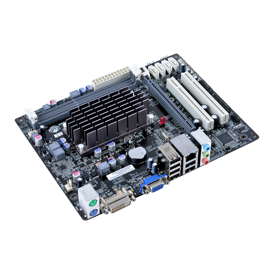
Page 9: Motherboard Components
Motherboard Components Table of Motherboard Components LABEL COMPONENTS 1. CPU_FAN CPU cooling fan connector 2. DDR3_1~2 240-pin DDR3 SDRAM slots 3. ATX_POWER Standard 24-pin ATX power connector 4. SATA1~4 Serial ATA 3Gb/s connectors 5. SPK Speaker header 6. F_PANEL Front panel switch/LED header 7. - Page 10 Memo Introducing the Motherboard...
-
Page 11: Installing The Motherboard
Chapter 2 Installing the Motherboard Safety Precautions • Follow these safety precautions when installing the motherboard • Wear a grounding strap attached to a grounded device to avoid dam- age from static electricity • Discharge static electricity by touching the metal case of a safely grounded object before working on the motherboard •... -
Page 12: Checking Jumper Settings
Do not over-tighten the screws as this can stress the motherboard. Checking Jumper Settings This section explains how to set jumpers for correct configuration of the motherboard. Setting Jumpers Use the motherboard jumpers to set system configuration options. Jumpers with more than one pin are numbered. -
Page 13: Checking Jumper Settings
Checking Jumper Settings The following illustration shows the location of the motherboard jumpers. Pin 1 is labeled. Jumper Settings Jumper Type Description Setting (default) 1-2: NORMAL 2-3: CLEAR CLR_CMOS 3-pin CLEAR CMOS Before clearing the CMOS, make sure to CLR_CMOS turn the system off. -
Page 14: Installing Hardware
Installing Hardware Installing Memory Modules This motherboard accommodates two memory module. It can support two 240-pin DDR3 1333(OC)/1066. The total memory capacity is 8 GB. DDR3 SDRAM memory module table Memory module Memory Bus DDR3 1333(OC) 667 MHz DDR3 1066 533 MHz You must install at least one module in any of the two slots. -
Page 15: Expansion Slots
Expansion Slots Installing Add-on Cards The slots on this motherboard are designed to hold expansion cards and connect them to the system bus. Expansion slots are a means of adding or enhancing the motherboard’s features and capabilities. With these efficient facilities, you can in- crease the motherboard’s capabilities by adding hardware that performs tasks that are not part of the basic system. - Page 16 Follow these instructions to install an add-on card: Remove a blanking plate from the system case corresponding to the slot you are going to use. Install the edge connector of the add-on card into the expansion slot. Ensure that the edge connector is correctly seated in the slot. Secure the metal bracket of the card to the system case with a screw.
-
Page 17: Connecting Optional Devices
Connecting Optional Devices Refer to the following for information on connecting the motherboard’s optional devices: F_AUDIO: Front Panel Audio header This header allows the user to install auxiliary front-oriented microphone and line- out ports for easier access. Signal Name Signal Name PORT 2L AUD_GND PORT 2R... - Page 18 CASE: Chassis Intrusion Detect Header This detects if the chassis cover has been removed. This function needs a chassis equipped with instrusion detection switch and needs to be enabled in BIOS. Pin 1-2 Function Short Case Open Open Case Close F_USB1~3: Front Panel USB 2.0 headers The motherboard has six USB 2.0 ports installed on the rear edge I/O port array.
- Page 19 SPDIFO: SPDIF out header This is an optional header that provides an S/PDIF (Sony/Philips Digital Interface) output to digital multimedia device through optical fiber or coaxial connector. Signal Name Function SPDIF SPDIF digital output +5VA 5V analog Power No pin Ground LPT: Onboard parallel port header This is a header that can be used to connect to the printer, scanner or other devices.
-
Page 20: Installing A Hard Disk Drive/Cd-Rom/Sata Hard Drive
Installing a SATA Hard Drive This section describes how to install a SATA hard drive. About SATA Connectors Your motherboard features four SATA connectors supporting a total of four drives. SATA refers to Serial ATA (Advanced Technology Attachment) is the standard inter- face for the IDE hard drives which are currently used in most PCs. -
Page 21: Connecting I/O Devices
Connecting I/O Devices The backplane of the motherboard has the following I/O ports: PS2 Mouse Use the upper PS/2 port to connect a PS/2 pointing device. PS2 Keyboard Use the lower PS/2 port to connect a PS/2 keyboard. DVI Port Connect the DVI port to the monitor. -
Page 22: Connecting Case Components
Connecting Case Components After you have installed the motherboard into a case, you can begin connecting the motherboard components. Refer to the following: Connect the CPU cooling fan cable to CPU_FAN. Connect the System cooling fan connector to SYS_FAN. Connect the case switches and indicator LEDs to the F_PANEL. Connect the standard power supply connector to ATX_POWER. - Page 23 CPU_FAN: CPU Cooling FAN Power Connector Signal Name Function System Ground Power +12V +12V Sense Sensor Control CPU FAN control Users please note that the fan connector supports the CPU cooling fan of 1.1A ~ 2.2A (26.4W max) at +12V. ATX_POWER: ATX 24-pin Power Connector Signal Name Signal Name...
-
Page 24: Front Panel Header
Front Panel Header The front panel header (F_PANEL) provides a standard set of switch and LED headers commonly found on ATX or Micro ATX cases. Refer to the table below for information: Signal Function Signal Function HD_LED_P Hard disk LED(+) 2 FP PWR/SLP *MSG LED(+) HD_LED_N Hard disk LED(- ) FP PWR/SLP *MSG LED(-) -
Page 25: Using Bios
Chapter 3 Using BIOS About the Setup Utility The computer uses the latest “American Megatrends Inc. ” BIOS with support for Windows Plug and Play. The CMOS chip on the motherboard contains the ROM setup instructions for configuring the motherboard BIOS. The BIOS (Basic Input and Output System) Setup Utility displays the system’s configuration status and provides you with options to set system parameters. -
Page 26: Resetting The Default Cmos Values
Press the delete key to access BIOS Setup Utility. Aptio Setup Utility - Copyright (C) 2010 American Megatrends, Inc. Main Advanced Chipset M.I.B III Boot Security Save & Exit Choose the system default BIOS Information laguage. System Laguage [English] :Select Screen System Date [Fri 04/22/2011] System Time... -
Page 27: Using Bios
In this manual, default values are enclosed in parenthesis. Submenu items are denoted by a triangle The default BIOS setting for this motherboard apply for most conditions with optimum performance. We do not suggest users change the default values in the BIOS setup and take no responsibility to any damage caused by changing the BIOS settings. -
Page 28: Advanced Menu
System Language (English) This item is used to set the language. System Date & Time The Date and Time items show the current date and time on the computer. If you are running a Windows OS, these items are automatically updated whenever you make changes to the Windows Date and Time Properties utility. -
Page 29: Lan Configuration
LAN Configuration The item in the menu shows the LAN-related information that the BIOS automatically detects. Aptio Setup Utility - Copyright (C) 2010 American Megatrends, Inc. Main Advanced Chipset M.I.B III Boot Security Save & Exit Enable or Disable Onboard LAN LAN Configuration Onboard LAN Controller [Enabled]... -
Page 30: Pc Health Status
PC Health Status On motherboards support hardware monitoring, this item lets you monitor the parameters for critical voltages, temperatures and fan speeds. Aptio Setup Utility - Copyright (C) 2010 American Megatrends, Inc. Main Advanced Chipset M.I.B III Boot Security Save & Exit Smart Fan Function CPU Tct1 System temperature... - Page 31 Smart Fan Mode (Normal) This item allows you to select the fan mode (Normal, Quiet, Silent, or Manual) for a better operation environment. If you choose Normal mode, the fan speed will be auto adjusted depending on the CPU temperature. If you choose Quite mode, the fan speed will be auto minimized for quiet environment.
-
Page 32: Power Management Setup
Power Management Setup This page sets up some parameters for system power management operation. Aptio Setup Utility - Copyright (C) 2010 American Megatrends, Inc. Main Advanced Chipset M.I.B III Boot Security Save & Exit Power Management Setup About Resume by RING Resume By RING [Disabled] Resume By USB (S3) -
Page 33: Acpi Settings
ACPI Settings The item in the menu shows the highest ACPI sleep state when the system enters suspend. Aptio Setup Utility - Copyright (C) 2010 American Megatrends, Inc. Main Advanced Chipset M.I.B III Boot Security Save & Exit ACPI Setting Select the highest ACPI sleep state the system will enter ACPI Sleep State... -
Page 34: Cpu Configuration
CPU Configuration The item in the menu shows the CPU configuration. Aptio Setup Utility - Copyright (C) 2010 American Megatrends, Inc. Main Advanced Chipset M.I.B III Boot Security Save & Exit Enable /Disable the AMD C&Q CPU Configuration Function. Nodeo: AMD E-350 Processor Dual Core Running @ 1623 MHz 1300 mV Max Speed: 1600 MHz... -
Page 35: Sata Configuration
SATA Configuration Use this item to show the mode of Serial ATA configuration options. Aptio Setup Utility - Copyright (C) 2010 American Megatrends, Inc. Main Advanced Chipset M.I.B III Boot Security Save & Exit Enable/Disable SATA Controller SATA Configuration Serial -ATA Controller [Enabled] SATA Mode [IDE]... -
Page 36: Usb Configuration
USB Configuration Use this item to show the information of USB configuration. Aptio Setup Utility - Copyright (C) 2010 American Megatrends, Inc. Main Advanced Chipset M.I.B III Boot Security Save & Exit USB Configuration All USB Devices [Enabled] Legacy USB Support [Enabled] :Select Screen :Select Item... - Page 37 Serial Port 0 Configuration Use this item to show the information of Serial Part 0 configuration. Aptio Setup Utility - Copyright (C) 2010 American Megatrends, Inc. Main Advanced Chipset M.I.B III Boot Security Save & Exit Serial Part 0 Configuration Enable or Disable Serial Serial Port [Enabled]...
- Page 38 Parallel Port Configuration Use this item to show the information of Parallel port configuration. Aptio Setup Utility - Copyright (C) 2010 American Megatrends, Inc. Main Advanced Chipset M.I.B III Boot Security Save & Exit Parallet Part O Configuration Enable or Disable Parellel Port (LPT/LPTE) Parallel Port [Enabled]...
-
Page 39: Trusted Computing
Trusted computing Use this item to show the information of trusted computing configuration. Aptio Setup Utility - Copyright (C) 2010 American Megatrends, Inc. Main Advanced Chipset M.I.B III Boot Security Save & Exit Enables or Disables TPM TPM Configuration support.O.S.will not show TPM SUPPORT [Disabled] TPM.Reset of platform is... -
Page 40: Chipset Menu
Chipset Menu The chipset menu items allows you to change the settings for the North Bridge chipset, South Bridge chipset and other system. Aptio Setup Utility - Copyright (C) 2010 American Megatrends, Inc. Main Advanced Chipset M.I.B III Boot Security Save & Exit North Bridge Parameters North Bridge South Bridge... - Page 41 South Bridge Scroll to this item and press <Enter> to view the following screen: Aptio Setup Utility - Copyright (C) 2010 American Megatrends, Inc. Main Advanced Chipset M.I.B III Boot Security Save & Exit SB Chipset Configuration Specify what state to go to when power is re-applied after Restore AC Power Loss [Power Off]...
-
Page 42: M.i.b Iii
M.I.B III Menu This page enables you to set the clock speed and system bus for your system. The clock speed and system bus are determined by the kind of processor you have installed in your system. Aptio Setup Utility - Copyright (C) 2010 American Megatrends, Inc. Main Advanced Chipset M.I.B III Boot... -
Page 43: Boot Menu
Boot Menu This page enables you to set the keyboard NumLock state. Aptio Setup Utility - Copyright (C) 2010 American Megatrends, Inc. Main Advanced Chipset M.I.B III Boot Security Save & Exit Select the keyboard NumLock Boot Configuration state Bootup NumLock State [On] Boot Option Priorities :Select Screen... -
Page 44: Security Menu
Security Menu This page enables you to set setup administrator and password. Aptio Setup Utility - Copyright (C) 2010 American Megatrends, Inc. Main Advanced Chipset M.I.B III Boot Security Save & Exit Set Setup Administrator Administrator Password Password :Select Screen :Select Item Enter : Select +/- :Change Opt. -
Page 45: Save & Exit Setup
Save & Exit Menu This page enables you to exit system setup after saving or without saving the changes. Aptio Setup Utility - Copyright (C) 2010 American Megatrends, Inc. Main Advanced Chipset M.I.B III Boot Security Save & Exit Exit system setup after saving Save Changes and Exit Discard Changes and Exit Save Changes and Reset... - Page 46 SATA: INTEL SSDSA2M080G2GC This items sets the system boot order. Using BIOS...
-
Page 47: Updating The Bios
Updating the BIOS You can download and install updated BIOS for this motherboard from the manufacturer’s Web site. New BIOS provides support for new peripherals, improve- ments in performance, or fixes for known bugs. Install new BIOS as follows: If your motherboard has a BIOS protection jumper, change the setting to allow BIOS flashing. - Page 48 Memo Using BIOS...
-
Page 49: Using The Motherboard Software
Chapter 4 Using the Motherboard Software About the Software DVD-ROM/CD-ROM The support software DVD-ROM/CD-ROM that is included in the motherboard package contains all the drivers and utility programs needed to properly run the bundled products. Below you can find a brief description of each software program, and the location for your motherboard version. -
Page 50: Running Setup
Drivers Click the Setup button to run the software installation program. Setup Select from the menu which software you want to install. Utilities Click the Utilities button to display the application software and other software utilities that are available on the disk. Select the sofware you want to install then follow installation procedure. - Page 51 Click Next. The following screen appears: Check the box next to the items you want to install. The default options are recom- mended. Click Next run the Installation Wizard. An item installation screen appears: Follow the instructions on the screen to install the items. Drivers and software are automatically installed in sequence.
-
Page 52: Manual Installation
Windows Vista/7 will appear below UAC (User Account Control) message after the system restart. You must select “Allow” to install the next driver. Continue this process to complete the drivers installation. Manual Installation Insert the disk in the DVD-ROM/CD-ROM drive and locate the PATH.DOC file in the root directory. -
Page 53: Trouble Shooting
Chapter 5 Trouble Shooting Start up problems during assembly After assembling the PC for the first time you may experience some start up problems. Before calling for technical support or returning for warranty, this chapter may help to address some of the common questions using some basic troubleshooting tips. -
Page 54: Start Up Problems After Prolong Use
2. From the BIOS setting, try to disable the Smartfan function to let the fan run at default speed. Doing a Load Optimised Default will also disable the Smartfan. Start up problems after prolong use After a prolong period of use your PC may experience start up problems again. This may be caused by breakdown of devices connected to the motherboard such as HDD, CPU fan, etc. - Page 56 Memo Trouble Shooting...
Need help?
Do you have a question about the HDC-M and is the answer not in the manual?
Questions and answers