Table of Contents
Advertisement
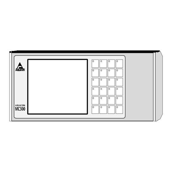
ARLACON MC300
Control system
User's manual
Product code 1003418
ARLACON MC300
Control system
user's manual
COMPACT SYSTEM
• up to 8 axes
• graphigal display
• ASCII keyboard
• McDos / McBasic
• RS232, RS232/422/485
• McWay 504/504 i/o each, 1,25ms
Arlacon Motion Controls
Control Techniques SKS Oy
Martinkyläntie 50 01720 VANTAA
tel +358-9-852 678 fax +358-9-852 6740
1.4.1997, Ari Lindvall
MC300MAE
1
Advertisement
Table of Contents

Summary of Contents for Arlacon MC300
- Page 1 ARLACON MC300 MC300MAE Control system User's manual Product code 1003418 ARLACON MC300 Control system user's manual COMPACT SYSTEM • up to 8 axes • graphigal display • ASCII keyboard • McDos / McBasic • RS232, RS232/422/485 • McWay 504/504 i/o each, 1,25ms...
- Page 2 Control Techniques SKS Oy Address: Control Techniques SKS Oy Martinkyläntie 50 SF-01720 Vantaa Finland Product: MC300 control units conform to the following Directives and Regulations EMC: Directive 89/336/EEC Generic Standards: EN 50081-2 EN 50082-2 The purpose of this equipment is to be used as a part of the electrical system of an industrial machine.
-
Page 3: Table Of Contents
Product code 1003418 Table of contents: 1. INTRODUCTION _______________________________________________________________ 4 1.1 GENERAL ............................4 1.2 MC300 FLUSH MOUNT CONTROL UNIT ..................4 1.3 MC300 CONTROL UNIT WITH ENCLOSURE ................5 1.4 MCWAY I/O SYSTEM ........................5 1.5 MCBASIC PROGRAMMING LANGUAGE ..................5 2. -
Page 4: Product Code 1003418
ASCII keyboard and a McWay connection for the i/o system. To get the MC300 operating you only need a 24Vdc power supply and a terminal or a PC for programming. The MC300 can also be configured as a "Dumb terminal" for use as user interface terminals for ARLACON control systems or other systems using RS-232, RS-422 or optical fibre communications. -
Page 5: Mc300 Control Unit With Enclosure
MC300 supports 16 logical axes of which up to 8 can be physical axes controlled by the system simultaneously. Up to 504 input bits and 504 output bits can be connected via the McWay I/O system. -
Page 6: Installation And Assembly
Product code 1003418 2. INSTALLATION AND ASSEMBLY This chapter describes the different versions of MC300 and the procedures for installing them in your system. For any work on the connections or inside parts of the unit, the power supply must be disconnected. - Page 7 The display/keyboard plastic membrane of the MC300 has transparent windows over the keyswitches to enable use of custom legends on the switches. A white plastic background with holes for the led lamps is also supplied for use with legends printed on transparent plastic.
-
Page 8: Mc300 With Enclosure
ENTER Fig 2.1.2, Keypad legend slip 2.2 MC300 with enclosure The MC300HTR with aluminium enclosure is designed for use as a hand terminal or for mounting on machines, walls etc. A support bracket with hand screws is also available. The enclosure is also equipped with two D-15 and a 5 pin DIN female connectors for electrical connections. -
Page 9: Control Unit Electrical Connections
Fig. 2.3.1 shows the MC300 control unit system board. Additionally, a daughter board DPI02410 is used in panel/flush mount versions for connections. In the MC300 with enclosure the connections go through D-15 connectors via a connector card at the end plate of the... - Page 10 ARLACON MC300 MC300MAE Control system User's manual Product code 1003418 +24V Fig. 2.3.1, MC300 system board The following significant parts are located on the system board: MC300 Power supply connector (20-28Vdc) Communications connector Analog I/O connector CPU service connector Memory type jumpers...
-
Page 11: Power Supply
When building complete systems with MC300 and McWay i/o modules note the system overall power requirement when using the same power supply. In the MC300 flush version the power supply is connected to the S1 connector on the system board. - Page 12 McBasic program being run. Redirecting console can be used to avoid this when running protocols written to use also ctrl-X. The MC300 can also connect to McNet RS485 local network via the CN: or LP: channel as a network peripheral device (see McNet documentation).
-
Page 13: Communications Connections
2.3.3 Communications connections MC300 with DPI02410 connection board The MC300 flush mount version is equipped with the DPI02410 connection board as standard. Two versions of this board are available, version A with connections for RS232/422 and version B with connections for RS232 / optical fibre. Use of optical fibre is recommended for McWay I/O system to ensure optimum EMC performance. - Page 14 Further stop switches can be connected in series with the emergency switch by removing the right jumper S5 on the ADP02908 connector board in the MC300 enclosure. After removing the left jumper on S5, the emergency loop is open at CN: connector S3 +EMRG and -EMRG pins.
-
Page 15: Wgt02310 Optical Fibre/ Rs232 /Rs422 General Transceiver
McWay equipment. It can be used for several purposes: To connect McWay modules to MC300 systems with optical fibre To connect McWay modules to MC300 systems with RS-422 with optical isolation in each segment. To provide isolation/optical fibre connection for MC300 serial communications... - Page 16 ARLACON MC300 MC300MAE Control system User's manual Product code 1003418 Fig. 2.3.4.1 shows the parts of a WGT02310 module FIBER IN FIBER OUT S3 RS-422 or RS-232 in/out S1 RS-422 IN A S5 emergency switch for S3 IN B EMRG+...
- Page 17 0V in WGT02310. If used with MC300 version with enclosure, pins 6 and 14 can be used for connecting power from WGT 24V supply to terminal. In this case, do not connect pins 9,10 and 13.
-
Page 18: Mcway I/O Modules
ARLACON MC300 series control unit. Modules are available for connecting position feedback controlled axes with either incremental or absolute encoders, digital and analog inputs and outputs. Up to 504 output bits and 504 input bits can be connected to the MC300 McWay loop with a refresh period of down to 1ms. -
Page 19: The European Emc Directive
These installations are described in ARLACON MC manuals. By following these installation practices the ARLACON components in the electrical system of the machine generally do not obstruct compliance. In complex cases, where it is difficult to install according to all instructions, and when the influence of other components must be considered, additional testing may be necessary to ensure compliance. - Page 20 ARLACON MC300 MC300MAE Control system User's manual Product code 1003418 Whenever possible, earth from control components and signal wiring shields should be connected to a separate earth called technical earth (TE), which is connected to the protective earth (PE) as near the factory earth potential as possible.
-
Page 21: Enclosure
TE to reduce common mode interference and load to TE. 2.6.5 Power supply Use a 24V power supply delivered by your ARLACON distributor. To comply with EN50081-2 requirements use a twisted pair of wire to feed the control unit and install the ferrite ring... -
Page 22: Mc300 Flush Mount Connections
If EN50081-1 levels for conducted emissions are necessary, use an additional RF filter available from your Arlacon distributor. 2.6.6 MC300 flush mount connections, Fig. 2.6.6.1 shows the recommended power supply and earth connections for MC300 flush mount control unit. good... -
Page 23: Mc300 With Enclosure, Connections
Fig. 2.6.6.1, MC300 flush mount, power supply and earth connections 2.6.7 MC300 with enclosure, connections Fig. 2.6.7.1 shows the recommended power supply and earth connections for MC300 control unit with enclosure. The same cable with a sufficient number of twisted pairs can be used for other signals such as communications signals. - Page 24 ARLACON MC300 MC300MAE Control system User's manual Product code 1003418 FERRITE RING SIGNAL CABLE SIGNAL WIRES Fig. 2.6.9 Signal cable ferrite suppressor...
-
Page 25: Power Up And Testing
McDos operating system of the MC300. The prompt D8:/> shows that the current drive and path is D8:/. There are 3(4) memory devices in the MC300 relevant for McDos all using a similar file and directory structure as found on diskettes etc. These are named:... -
Page 26: Initializing The System
To be able to use certain system functions such as the McWay i/o system or servo control, some initialization procedures are necessary. 3.2.1 McWay configuration To use McWay modules in MC300 their communication baud rate must be set to 1,25M. Set the configuration of the installed I/O system using the McBasic WAYMOD$= command. - Page 27 To determine the right settings for each I/O module type please refer to the ARLACON McWay Distributed I/O System User’ s Manual. MC300 has a McWay I/O loop with 504 bits in and 504 bits out. The number of bits used by different modules depends on the module type.
-
Page 28: Starting The Servo System
FOLLOW and MOVEPROF. The default DRIVETYPE for the first four axes (X,Y,Z,W) in MC300 is 1 (standard closed loop with ±10V reference) and 176 (virtual) for all other axes. Use the McBasic DRIVETYPE= command to set axes according to your needs. - Page 29 FOR n=0 TO 15 GAIN(n)=150 : INTG(n)=0 : DERV(n)=2 NEXT n See McBasic manual for more information. Fig 3.3 shows the principle of the servo control system for one axis. ARLACON MOTION CONTROL SYSTEM SERVO DRIVE SERVO- POSITION McBASIC MOTION...
- Page 30 ARLACON MC300 MC300MAE Control system User's manual Product code 1003418 PIDFREQ=500 RESX=125 ' 125 pulse edges/mm MAXERRX=10 ' poserr >10mm cuts off servo GAINX=100 ' gain INTGX=0 : DERVX=0 : SCOMPX=0 ' others off SPEEDX=200 ' 200 mm/s ACCELX=400 ' 0.5 s ramp (200/400=0.5) FILTERSIZEX=20 ‘...
-
Page 31: Programming The Mc300
RAM drives of different sizes can be used, only one device can be set as FLASH and one as EPROM. 4.2 DISPLAY AND KEYBOARD The display and keyboard in the MC300 can be used from programs by opening it for a suitable logical device number: OPEN #5,”TR:”... - Page 32 ASCII -keyboard An ASCII keyboard can be connected to the standard 5-pin connector in the end of the MC300 version with enclosure. In the MC300 flush mount version a keyboard can be connected to S6 on the system board using an optional adapter cable (50cm) supplied separately. With the adapter cable the keyboard connector can be installed conveniently near the unit.
-
Page 33: I/O Usage
DO UNTIL INP(35)=1 : LOOP 'wait until INP(35) on For more details refer to McBasic manual. A special feature of the MC300 McWay based i/o is the error values. In addition to the usual 0 and 1 the INP( ) and OUT( ) funtions can return negative values if there is a fatal communications error in McWay data transmission. - Page 34 ARLACON MC300 MC300MAE Control system User's manual Product code 1003418 The following default settings can be used (PROCOMM +): Line/port setup (Alt P) Use the port you wish with 9600 baud 8 bit data no parity 2 stop bits Terminal options (general) (Alt S)
-
Page 35: Memory
To ensure reliable operation and minimize down-time of applications it is advisable to save the application program and possible critical data files in the MC300 FLASH EPROM after finishing program development. Saving the program with the filename “ WAKEUP.BA” allows automatic loading of the program in case the program is lost from the work memory. -
Page 36: Ram Memory
4.6.5 Emergency stop switch An emergency stop switch is available for the MC300 with enclosure. It is installed as shown in fig. 2.2.2. Pushing the emergency stop switch cuts the connection between pins 8 and 15 at the :CN...
Need help?
Do you have a question about the MC300 and is the answer not in the manual?
Questions and answers