Table of Contents
Advertisement
Advertisement
Table of Contents

Subscribe to Our Youtube Channel
Related Manuals for ECS G43T-M


Summary of Contents for ECS G43T-M
- Page 3 Preface Copyright This publication, including all photographs, illustrations and software, is protected under international copyright laws, with all rights reserved. Neither this manual, nor any of the material contained herein, may be reproduced without written consent of the author. Version 1.0 Disclaimer The information in this document is subject to change without notice.
-
Page 4: Declaration Of Conformity
Declaration of Conformity This device complies with part 15 of the FCC rules. Operation is subject to the following conditions: • This device may not cause harmful interference, and • This device must accept any interference received, including interfer- ence that may cause undesired operation Canadian Department of Communications This class B digital apparatus meets all requirements of the Canadian Interference- causing Equipment Regulations. -
Page 5: Table Of Contents
T T T T T ABLE OF CONTENTS ABLE OF CONTENTS ABLE OF CONTENTS ABLE OF CONTENTS ABLE OF CONTENTS Preface Chapter 1 Introducing the Motherboard Introduction..................1 Feature....................2 Motherboard Components.............4 Chapter 2 7 7 7 7 7 Installing the Motherboard Safety Precautions................7 Choosing a Computer Case............7 Installing the Motherboard in a Case..........7... - Page 6 Integrated Peripherals............35 Power Management Setup..........36 PNP/PCI Configurations...........37 PC Health Status...............38 Frequency/Voltage Control..........40 Load Default Settings............41 Supervisor Password............41 User Password..............4 Save & Exit Setup..............42 Exit Without Saving............42 43 43 43 43 Chapter 4 Using the Motherboard Software About the Software CD-ROM............43 Auto-installing under Windows XP/Vista........43 Running Setup..............44 Manual Installation................48...
-
Page 7: Introducing The Motherboard
Chapter 1 Introducing the Motherboard Introduction Thank you for choosing the G43T-M motherboard. This motherboard is a high performance, enhanced function motherboard designed to support the LGA775 socket ® Intel Yorkfield/Wolfdale family processors for high-end business or personal desk- top markets. -
Page 8: Feature
Feature Processor ® The motherboard uses an LGA775 type of Intel Yorkfield/Wolfdale family processors that carries the following features: ® • Accommodates Intel Yorkfield/Wolfdale family processors • Supports a system bus (FSB) of 1333/1066/800 MHz • Supports “Hyper-Threading” technology CPU “Hyper-Threading”... -
Page 9: Onboard Lan
Audio • 8 Channel High Definition Audio Codec • All DACs support 192K/96K/48K/44.1KHz DAC sample rate • High-quality analog differential CD input • Meets Microsoft WLP 3.08 audio requirements • Direct Sound 3D compatible Onboard LAN • Integrated 10/100/1000 Mbps IEEE 802.3 compliant Expansion Options The motherboard comes with the following expansion options: •... -
Page 10: Motherboard Components
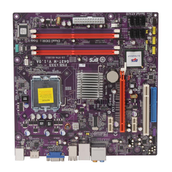
Motherboard Components Introducing the Motherboard... - Page 11 Table of Motherboard Components LABEL COMPONENTS 1. CPU Socket ® LGA775 socket for Intel Yorkfield/Wolfdale CPUs 2. CPU_FAN CPU cooling fan connector Onboard Serial Port header 3. COM 240-pin DDR2 SDRAM slots 4. DDR2_DIMM1~4 5. ATX_POWER Standard 24-pin ATX power connector System cooling fan connector 6.
- Page 12 Memo Introducing the Motherboard...
-
Page 13: Installing The Motherboard
Chapter 2 Installing the Motherboard Safety Precautions • Follow these safety precautions when installing the motherboard • Wear a grounding strap attached to a grounded device to avoid dam- age from static electricity • Discharge static electricity by touching the metal case of a safely grounded object before working on the motherboard •... -
Page 14: Checking Jumper Settings
Do not over-tighten the screws as this can stress the motherboard. Checking Jumper Settings This section explains how to set jumpers for correct configuration of the motherboard. Setting Jumpers Use the motherboard jumpers to set system configuration options. Jumpers with more than one pin are numbered. -
Page 15: Checking Jumper Settings
Checking Jumper Settings The following illustration shows the location of the motherboard jumpers. Pin 1 is labeled. Jumper Settings Jumper Type Description Setting (default) 1-2: NORMAL 2-3: CLEAR CLR_CMOS 3-pin CLEAR CMOS Before clearing the CMOS, make sure to CLR_CMOS turn the system off. -
Page 16: Connecting Case Components
To avoid the system instability after clearing CMOS, we recommend users to enter the main BIOS setting page to “Load Optimized Defaults” and then “Save & Exit Setup”. 2. Make sure the power supply provides enough 5VSB voltage before se- lecting the 5VSB function. -
Page 17: Atx 24-Pin Power Connector
CPU_FANS/SYS_FAN: FAN Power Connector Signal Name Function System Ground Power +12V +12V Sense Sensor Users please note that the fan connector supports the CPU cooling fan of 1.1A ~ 2.2A (26.4W max) at +12V. ATX_ POWER: ATX 24-pin Power Connector Signal Name Signal Name +3.3V... -
Page 18: Front Panel Header
Front Panel Header The front panel header (F_PANEL) provides a standard set of switch and LED headers commonly found on ATX or Micro ATX cases. Refer to the table below for informa- tion: Signal Function Signal Function HD_LED_P Hard disk LED(+) 2 FP PWR/SLP *MSG LED(+) HD_LED_N Hard disk LED(- ) FP PWR/SLP *MSG LED(-) -
Page 19: Installing Hardware
Installing Hardware Installing the Processor Caution: When installing a CPU heatsink and cooling fan make sure that you DO NOT scratch the motherboard or any of the surface-mount resistors with the clip of the cooling fan. If the clip of the cooling fan scrapes across the motherboard, you may cause serious damage to the motherboard or its components. -
Page 20: Cpu Installation Procedure
CPU Installation Procedure The following illustration shows CPU installation components. A. Read and follow the instructions shown on the sticker on the CPU cap. B. Unload the cap · Use thumb & forefinger to hold the lifting tab of the cap. ·... -
Page 21: Installing Memory Modules
Installing Memory Modules This motherboard accomodates four memory modules. It can support four 240-pin DDR2 800/667. The total memory capacity is 8 GB*. DDR2 SDRAM memory module table Memory module Memory Bus DDR2 667 333 MHz DDR2 800 400 MHz You must install at least one module in any of the four slots. - Page 22 Due to chipset limitation, please follow closely the table below when installing memory for dual channel or single channel mode operation. Memory Installation Combination For dual channel configuration, you must always install identical (the same board, speed, size and chip-type) DDR2 DIMM pair in the slots of the same color. Mem ory Installation Com bination -- Dual Channel Mode DS =>...
- Page 23 Table A: DDR2 (memory module) QVL (Qualified Vendor List) The following DDR2 800/667 memory modules and combination have been tested and qualified for use with this motherboard. DIMM Slot: DS-Double side, SS-Single Side, 0-No DIMM socket DIMM Slot Type Size Vendor Module Nam e Infineon...
-
Page 24: Installing Sata Hard Drive
Installing a Hard Dish Drive/CD-ROM/SATA Hard Drive This section describes how to install IDE devices such as a hard disk drive and a CD- ROM drive. About IDE Devices Your motherboard has one IDE channel interface. An IDE ribbon cable supporting two IDE devices is bundled with the motherboard. - Page 25 Refer to the illustration below for proper installation: Attach either cable end to the connector on the motherboard. Attach the other cable end to the SATA hard drive. Attach the SATA power cable to the SATA hard drive and connect the other end to the power supply.
-
Page 26: Installing Add-On Cards
Installing Add-on Cards The slots on this motherboard are designed to hold expansion cards and connect them to the system bus. Expansion slots are a means of adding or enhancing the motherboard’s features and capabilities. With these efficient facilities, you can in- crease the motherboard’s capabilities by adding hardware that performs tasks that are not part of the basic system. - Page 27 Follow these instructions to install an add-on card: Remove a blanking plate from the system case corresponding to the slot you are going to use. Install the edge connector of the add-on card into the expansion slot. Ensure that the edge connector is correctly seated in the slot. Secure the metal bracket of the card to the system case with a screw.
-
Page 28: Connecting Optional Devices
Connecting Optional Devices Refer to the following for information on connecting the motherboard’s optional devices: F_AUDIO: Front Panel Audio header This header allows the user to install auxiliary front-oriented microphone and line- out ports for easier access. Signal Name Signal Name PORT 1L AUD_GND PORT 1R... - Page 29 SATA1~6: Serial ATA connectors These connectors are use to support the new Serial ATA devices for the highest date transfer rates (3.0 Gb/s), simpler disk drive cabling and easier PC assembly. It elimi- nates limitations of the current Parallel ATA interface. But maintains register com- patibility and software compatibility with Parallel ATA.
- Page 30 COM: Onboard Serial Port header Connect a serial port extension bracket to this header to add a second serial port to your system. Signal Name Function DCDB Data Carrier Detect SINB Serial Input SOUTB UART B Serial Output DTRB UART B Data Terminal Ready Ground DSRB Data Set Ready...
-
Page 31: Connecting I/O Devices
Connecting I/O Devices The backplane of the motherboard has the following I/O ports: PS2 Mouse Use the upper PS/2 port to connect a PS/2 pointing device. PS2 Keyboard Use the lower PS/2 port to connect a PS/2 keyboard. VGA Port Connect your monitor to the VGA port. - Page 32 Memo Installing the Motherboard...
-
Page 33: Using Bios
Chapter 3 Using BIOS About the Setup Utility The computer uses the latest “American Megatrends Inc.” BIOS with support for Windows Plug and Play. The CMOS chip on the motherboard contains the ROM setup instructions for configuring the motherboard BIOS. The BIOS (Basic Input and Output System) Setup Utility displays the system’s configuration status and provides you with options to set system parameters. -
Page 34: Bios Navigation Keys
Press DEL to enter SETUP Press the delete key to access the BIOS Setup Utility. CMOS Setup Utility -- Copyright (C) 1985-2008, American Megatrends, Inc. Standard CMOS Setup Frequency/Voltage Control Advanced Setup Load Default Settings Advanced Chipset Setup Supervisor Password Integrated Peripherals User Password Power Management Setup... -
Page 35: Updating The Bios
Updating the BIOS You can download and install updated BIOS for this motherboard from the manufacturer’s Web site. New BIOS provides support for new peripherals, improve- ments in performance, or fixes for known bugs. Install new BIOS as follows: If your motherboard has a BIOS protection jumper, change the setting to allow BIOS flashing. -
Page 36: Standard Cmos Setup
Standard CMOS Setup This option displays basic information about your system. CMOS Setup Utility - Copyright (C) 1985-2008, American Megatrends, Inc. Standard CMOS Setup Date (www mm:dd:yy) Mon 04/28/2008 Help Item Time (hh:mm:ss) 05 : 30 : 04 User [Enter], [TAB] SATA1 Not Detected or [SHIFT-TAB] to... - Page 37 Type (Auto) Use this item to configure the type of the IDE device that you specify. If the feature is enabled, it will enhance hard disk performance by reading or writing more data during each transfer. LBA/Large Mode (Auto) Use this item to set the LAB/Large mode to enhance hard disk performance by optimizing the area the hard disk is visited each time.
-
Page 38: Advanced Setup
Advanced Setup This page sets up more advanced information about your system. Handle this page with caution. Any changes can affect the operation of your computer. CMOS Setup Utility - Copyright (C) 1985-2008, American Megatrends, Inc. Advanced Setup Thermal Management Enabled Help Item TM Status... - Page 39 APIC Mode (Enabled) This item allows you to enable or disable the APCI (Advanced Programmable Inter- rupt Controller) mode. APIC provides symmetric multi-processing (SMP) for sys- tems, allowing support for up to 60 processors. 1st/2nd/3rd Boot Device (Hard Disk Drive/CD/DVD/Removable Dev.) Use this item to determine the device order the computer used to look for an operating system to load at start-up time.
-
Page 40: Advanced Chipset Setup
Advanced Chipset Setup This page sets up more advanced information about your system. Handle this page with caution. Any changes can affect the operation of your computer. CMOS Setup Utility - Copyright (C) 1985-2008, American Megatrends, Inc. Advanced Chipset Setup DRAM Frequency Auto Help Item... -
Page 41: Integrated Peripherals
Integrated Peripherals This page sets up some parameters for peripheral devices connected to the system. CMOS Setup Utility - Copyright (C) 1985-2008, American Megatrends, Inc. Integrated Peripherals Onboard SATA Mode Enhanced Help Item Onboard LAN Function Enabled Onboard LAN Boot ROM Disabled Options Onboard AUDIO Function... -
Page 42: Power Management Setup
Power Management Setup This page sets up some parameters for system power management operation. CMOS Setup Utility - Copyright (C) 1985-2008, American Megatrends, Inc. Power Management Setup Help Item ACPI Suspend Type S3 (STR) Soft-off by PWR-BTTN Instant Off PWRON After PWR-Fail Power Off Select the ACPI Resume by Ring... -
Page 43: Pnp/Pci Configurations
Resume By PS2 MS (S3) (Disabled) This item enables or disables you to allow mouse activity to awaken the system from power saving mode. Resume on RTC Alarm (Disabled) The system can be turned off with a software command. If you enable this item, the system can automatically resume at a fixed time based on the system’s RTC (realtime clock). -
Page 44: Pc Health Status
PC Health Status On motherboards support hardware monitoring, this item lets you monitor the parameters for critical voltages, temperatures and fan speeds. CMOS Setup Utility - Copyright (C) 1985-2008, American Megatrends, Inc. PC Health Status Help Item -=- System Hardware Monitor-=- Smart Fan Function Press Enter Shutdown Temperature... - Page 45 ECS supports the latest PECI host technology. While using Wolfdale or Yorkfield CPU, the original images of the BIOS item “PC Health Status” and “Smart FAN Function” will be replaced by PECI mode and negative number. (The max data from PECI is zero.) CMOS Setup Utility - Copyright (C) 1985-2008, American Megatrends, Inc.
-
Page 46: Frequency/Voltage Control
Shutdown Temperature (Disabled) Enable you to set the maximum temperature the system can reach before powering down. System Component Characteristics These items display the monitoring of the overall inboard hardware health events, such as System & CPU temperature, CPU & DIMM voltage, CPU & system fan speed,...etc. -
Page 47: Load Default Settings
CPU Over-clocking Func. (Disabled) This item decides the CPU over-clocking function/frequencyinstalled in your sys- tem. If the over-clocking fails, please turn offthe system power. And then, hold the PageUp key (similar to theClear CMOS function) and turn on the power, the BIOS willrecover the safe default. -
Page 48: User Password
User Password This page helps you install or change a password. CMOS Setup Utility - Copyright (C) 1985-2008, American Megatrends, Inc. User Password User Password : Not Installed Help item Change User Password Press Enter Install or Change the password. : Move Enter : Select +/-/: Value... -
Page 49: Using The Motherboard Software
Chapter 4 Using the Motherboard Software About the Software CD-ROM The support software CD-ROM that is included in the motherboard package contains all the drivers and utility programs needed to properly run the bundled products. Below you can find a brief description of each software program, and the location for your motherboard version. -
Page 50: Running Setup
Setup Tab Setup Click the Setup button to run the software installation program. Select from the menu which software you want to install. Browse CD The Browse CD button is the standard Windows command that allows you to open Windows Explorer and show the contents of the support CD. - Page 51 Click Next. The following screen appears: Check the box next to the items you want to install. The default options are recom- mended. Click Next run the Installation Wizard. An item installation screen appears: Follow the instructions on the screen to install the items. 1.
- Page 52 Method 1. Run Reboot Setup Windows Vista will block startup programs by default when installing drivers after the system restart. You must select taskbar icon Run Blocked Program and run Reboot Setup to install the next driver, until you finish all drivers installation. Method 2.
- Page 53 Select Classic View. Set User Account. Select Turn User Account Control on or off and press Continue. Using the Motherboard Software...
-
Page 54: Manual Installation
Disable User Account Control (UAC) to help protect your computer item and press OK, then press Restart Now. Then you can restart your computer and continue to install drivers without running blocked programs. Manual Installation Insert the CD in the CD-ROM drive and locate the PATH.DOC file in the root directory. -
Page 55: Hdmi Audio Setting Sop
HDMI Audio setting SOP OS: XP system 1. Control Panel-->Sound and Audio Device Properties a. Audio--> Sound playback--> Default device--> HD Auido Output b. Audio--> Sound playback--> Default device--> HDMI Auido Output a. User Playback Audio speaker function working b. User Playback HDMI speaker function working Using the Motherboard Software... - Page 56 OS: Vista system Control Panel--> Soundback--> Sound--> Digital Output Device (HDMI) --> Set Default 1. Volume --> Playback 2. Digital Output Device (HDMI) --> Set Default --> OK User HDMI Playback function working Using the Motherboard Software...
- Page 57 3. Speaker --> Set Default --> OK User Speaker Palyback function working 4. SPDIF-Out --> Set Default --> OK User SPDIF-Out Playback function working This concludes chapter 4. Using the Motherboard Software...
- Page 58 Memo Using the Motherboard Software...
Need help?
Do you have a question about the G43T-M and is the answer not in the manual?
Questions and answers