
Related Manuals for Honda WX10T


Summary of Contents for Honda WX10T
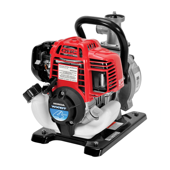
- Page 1 Owner s Manual WATER PUMP WX10T Click to Save As Includes US and Canadian Models 2014 Honda Motor Co., Ltd. -All Rights Reserved...
- Page 2 The information and specifications included in this publication were in effect at the time of approval for printing. Honda Motor Co., Ltd. reserves the right, however, to discontinue or change specifications or design at any time without notice and without incurring any obligation whatsoever.
- Page 3 INTRODUCTION Congratulations on your selection of a Honda water pump. We are certain you will be pleased with your purchase of one of the finest water pumps on the market. We want to help you get the best results from your new water pump and to operate it safely.
- Page 4 INTRODUCTION A FEW WORDS ABOUT SAFETY Your safety and the safety of others are very important. And using this water pump safely is an important responsibility. To help you make informed decisions about safety, we have provided operating procedures and other information on labels and in this manual.
-
Page 5: Table Of Contents
CONTENTS PUMP SAFETY................5 IMPORTANT SAFETY INFORMATION ......... 5 SAFETY LABEL LOCATIONS............7 CONTROLS................. 8 COMPONENT & CONTROL LOCATIONS........8 CONTROLS ................9 Ignition Switch..............9 Choke Lever ................. 9 Throttle Lever ..............10 Recoil Starter Grip ............... 10 BEFORE OPERATION ..............11 ARE YOU READY TO GET STARTED?........ - Page 6 Carburetor Modification for High Altitude Operation....57 Emission Control System Information........58 Air Index ................60 Specifications ..............61 CONSUMER INFORMATION............62 Dealer Locator Information ........... 62 Honda Publications ............. 62 Customer Service Information ..........63 QUICK REFERENCE INFORMATION......Inside back cover...
-
Page 7: Pump Safety
PUMP SAFETY IMPORTANT SAFETY INFORMATION The Honda WX10T pump is designed to pump only fresh water that is not intended for human consumption, and other uses can result in injury to the operator or damage to the pump and other property. - Page 8 PUMP SAFETY Hot Exhaust The muffler becomes very hot during operation and remains hot for a while after stopping the engine. Be careful not to touch the muffler while it is hot. Let the engine cool before transporting the pump or storing it indoors.
-
Page 9: Safety Label Locations
The labels shown here contain important safety information. Please read them carefully. These labels are considered permanent parts of your pump. If a label comes off or becomes hard to read, contact an authorized Honda servicing dealer for a replacement. * *... -
Page 10: Controls
CONTROLS COMPONENT & CONTROL LOCATIONS CHOKE LEVER SPARK PLUG (inside the top cover) PRIMING PUMP TOP COVER MUFFLER (inside the top cover) OIL FILLER CAP RECOIL STARTER STARTER GRIP FUEL TANK FUEL TANK CAP PRIMING WATER FILLER CAP CARRYING HANDLE STRAINER DISCHARGE PORT THROTTLE LEVER... -
Page 11: Controls
CONTROLS CONTROLS Ignition Switch The ignition switch controls the ignition system. The ignition switch must be in the ON position for the engine to run. Turning the ignition switch to the OFF position stops the engine. IGNITION SWITCH Choke Lever CHOKE LEVER The choke lever opens and closes the choke valve in the carburetor. -
Page 12: Throttle Lever
CONTROLS Throttle Lever The throttle lever controls engine THROTTLE LEVER speed. Moving the throttle lever in the SLOW directions shown makes the engine run faster or slower. FAST Pump output is controlled by adjusting the throttle lever. At the FAST position, the pump will deliver the highest output volume. -
Page 13: Before Operation
BEFORE OPERATION ARE YOU READY TO GET STARTED? Your safety is your responsibility. A little time spent in preparation will significantly reduce your risk of injury. Knowledge Read and understand this manual. Know what the controls do and how to operate them. Familiarize yourself with the pump and its operation before you begin pumping. -
Page 14: Check The General Condition Of The Pump
BEFORE OPERATION Check the General Condition of the Pump • Before each use, look around and underneath the engine for signs of oil or gasoline leaks. • Remove any excessive dirt or debris, especially around the engine muffler, and recoil starter. •... -
Page 15: Operation
OPERATION SAFE OPERATING PRECAUTIONS To safely realize the full potential of this pump, you need a complete understanding of its operation and a certain amount of practice with its controls. Before operating the pump for the first time, please review the IMPORTANT SAFETY INFORMATION on page 5 and the chapter titled BEFORE OPERATION. - Page 16 OPERATION Do not allow the pump to tip over or fall in its side during use. If the pump is not positioned upright or if there is not enough space around the pump, cooling air can become restricted or the engine exhaust may be obstructed, causing engine damage.
-
Page 17: Pump Placement
OPERATION PUMP PLACEMENT Always position the pump in an upright position on a firm level surface at least 3 feet (1 meter) away from any walls or other equipment. For best pump performance, place the pump near the water level, and use hoses that are no longer than necessary. -
Page 18: Suction Hose Installation
OPERATION SUCTION HOSE INSTALLATION Use the hose, hose connector, and hose clamp provided with the pump. The suction hose must be reinforced with a noncollapsible wall or braided wire construction to prevent suction hose collapse. The suction hose should be no longer than necessary. Pump performance is best when the pump is near the water level, and the hoses are short. -
Page 19: Discharge Hose Installation
OPERATION DISCHARGE HOSE INSTALLATION 1.Verify that the hose coupling packing is in good condition. 2.Securely tighten the hose connector to the pump discharge port. 3.Install the discharge hose to the hose connector. Use a hose clamp to securely fasten the discharge hose to prevent the discharge hose from disconnecting from the hose connector under high pressure. -
Page 20: Optional Garden Hose Installation (Discharge Only)
OPERATION OPTIONAL GARDEN HOSE INSTALLATION (discharge only) An adapter is supplied with the pump for optional connection of a garden hose to the pump discharge port. Garden hose is a convenient and economical option for carrying the discharged water, though its smaller diameter will reduce the maximum discharge capacity of the pump. -
Page 21: Priming The Pump
OPERATION PRIMING THE PUMP Before starting the engine, remove the filler cap from the pump chamber, and fill the pump chamber with water up to its priming water filling level. Reinstall the filler cap, and tighten it securely. Operating the pump dry will destroy the pump seal. If the pump has been operated dry, stop the engine immediately, and allow the pump to cool before priming. - Page 22 OPERATION If the discharge hose must run across a roadway, the hose should cross the roadway perpendicular to traffic flow. Also, heavy boards should be placed next to the hose so the motor vehicle weight does not shut off the discharge as vehicles cross over the hose. BOARDS DISCHARGE HOSE Driving over a discharge hose while the pump is running, or even...
-
Page 23: Starting The Engine
OPERATION STARTING THE ENGINE 1.To start a cold engine, move the choke lever to the CLOSED position. To restart a warm engine, leave the choke lever in the OPEN position. CHOKE LEVER CLOSED 2.Move the throttle lever away from the SLOW position, about 1/3 of the way toward the FAST position. - Page 24 OPERATION 3.Press the priming pump repeatedly until fuel can be seen in the clear-plastic fuel return tube. FUEL RETURN TUBE (clear-plastic tube) PRIMING PUMP 4.Turn the ignition switch to the ON position. IGNITION SWITCH...
- Page 25 OPERATION 5.Hold the carrying handle securely and pull the starter grip lightly until you feel resistance, then pull briskly in the direction of the arrow as shown below. Do not allow the recoil starter grip to snap back against the engine. Return it gently to prevent damage to the starter.
-
Page 26: Setting Engine Speed
OPERATION SETTING ENGINE SPEED After starting the engine, move the throttle lever to the FAST position for self-priming, and check pump output. Pump output is controlled by adjusting engine speed. Moving the throttle lever in the FAST direction will increase pump output, and moving the throttle lever in the SLOW direction will decrease pump output. -
Page 27: Stopping The Engine
OPERATION STOPPING THE ENGINE To stop the engine in an emergency, simply turn the ignition switch to the OFF position. Under normal conditions, use the following procedure. 1.Move the throttle lever to the SLOW position. SLOW THROTTLE LEVER 2.Turn the ignition switch to the OFF position. IGNITION SWITCH After use, remove the pump drain plug (see page 47), and drain the pump chamber. -
Page 28: Servicing Your Pump
Remember that an authorized Honda servicing dealer knows your pump best and is fully equipped to maintain and repair it. To ensure the best quality and reliability, use only new, Honda Genuine parts or their equivalents for repair and replacement. -
Page 29: Maintenance Safety
SERVICING YOUR PUMP MAINTENANCE SAFETY Some of the most important safety precautions follow. However, we cannot warn you of every conceivable hazard that can arise in performing maintenance. Only you can decide whether or not you should perform a given task. Failure to properly follow maintenance instructions and precautions can cause you to be... -
Page 30: Maintenance Schedule
— (1) Service more frequently when used in dusty areas. (2) These items should be serviced by your Honda servicing dealer, unless you have the proper tools and are mechanically proficient. Refer to the Honda shop manual for service procedures. See "Honda Publications" on page 62 for ordering information. -
Page 31: Refueling
SERVICING YOUR PUMP REFUELING Check the fuel level by looking through the translucent fuel tank. If the fuel level is low, refuel in a well-ventilated area with the engine stopped. If the engine has been running, allow it to cool first. Never refuel the engine inside a building where gasoline fumes can reach flames or sparks. -
Page 32: Fuel Recommendations
SERVICING YOUR PUMP To refuel, rest the engine on the ground with the fuel tank cap facing up, as shown. Remove the fuel tank cap, and fill the tank with gasoline to the maximum fuel level. Refuel carefully to avoid spilling fuel. Do not overfill. -
Page 33: Engine Oil Level Check
SERVICING YOUR PUMP ENGINE OIL LEVEL CHECK Check the engine oil level before each use, or every 10 hours if operated continuously. Check the engine oil level with the engine stopped and in a level position. 1.Remove the oil filler cap. 2.Check the oil level. -
Page 34: Engine Oil Change
SERVICING YOUR PUMP ENGINE OIL CHANGE Drain the used oil while the engine is warm. Warm oil drains quickly and completely. 1.Check that the fuel tank cap is tightened securely. 2.Place a suitable container next to the engine to catch the used oil. 3.Remove the oil filler cap and drain the oil into the container by tipping the engine toward the oil filler neck. - Page 35 SERVICING YOUR PUMP 4.With the engine in a level position, fill to the upper limit with the recommended oil (see page 34). Some oil will remain in the engine after draining. When refilling with fresh oil, start with less than 2 oz (0.08 L). Slowly add enough oil to fill to the upper limit as shown below.
-
Page 36: Engine Oil Recommendations
SERVICING YOUR PUMP ENGINE OIL RECOMMENDATIONS Oil is a major factor affecting performance and service life. Use 4-stroke automotive detergent oil. Use 4-stroke motor oil that meets or exceeds the requirements for API service category SJ or later (or equivalent). Always check the API service label on the oil container to be sure it includes the letters SJ or later (or equivalent). -
Page 37: Servicing Your Pump (Continued)
SERVICING YOUR PUMP AIR CLEANER SERVICE Move the choke lever to the CLOSED (upwards) position (see page 9). Press the latch tab on the top of the air cleaner cover. Tilt the top of the air cleaner cover back and unhook the two lower tabs, and remove the cover. -
Page 38: Air Filter Cleaning
SERVICING YOUR PUMP AIR FILTER CLEANING A dirty air filter will restrict air flow to the carburetor, reducing engine performance. If you operate the pump in very dusty areas, clean the air filter more frequently than specified in the Maintenance Schedule (see page 28). -
Page 39: Spark Plug Service
SERVICING YOUR PUMP SPARK PLUG SERVICE Recommended spark plug: CMR5H (NGK) Incorrect spark plugs can cause engine damage. 1.Loosen the 5 mm hex bolt with a hexagon wrench, and then remove the top cover. • You may be injured from rotating parts or burned by the muffler. - Page 40 SERVICING YOUR PUMP 2.First remove any dirt from around the spark plug area, and then disconnect the spark plug cap. 3.Remove the spark plug with a spark plug wrench. SPARK PLUG CAP SPARK PLUG WRENCH 4.Inspect the spark plug. Replace it SIDE ELECTRODE if the electrodes are worn, or if the insulator is cracked or...
- Page 41 SERVICING YOUR PUMP 7.After the spark plug seats, tighten with a spark plug wrench to com- press the washer. If reinstalling the used spark plug, tighten 1/8–1/4 turn after the spark plug seats. If installing a new spark plug, tighten 1/2 turn after the spark plug seats.
-
Page 42: Cooling Fin Inspection
SERVICING YOUR PUMP COOLING FIN INSPECTION 1.Remove the top cover (see page 37). 2.Inspect the engine cooling fins, and clean out debris if they are clogged. COOLING FINS 3.Install the top cover, and tighten the 5 mm hex bolt securely with a hexagon wrench. -
Page 43: Fuel Filter Inspection And Fuel Tank Cleaning
SERVICING YOUR PUMP FUEL FILTER INSPECTION and FUEL TANK CLEANING 1.Check that the oil filler cap is tightened securely. 2.Remove the fuel tank cap, and drain the fuel into an approved gasoline container by tipping the engine toward the fuel filler neck. Gasoline is highly flammable and explosive. - Page 44 SERVICING YOUR PUMP 3.Pull the fuel filter out through the fuel filler neck by hooking the black fuel tube with a piece of wire, such as a partly straightened paper clip. 4.Inspect the fuel filter. If the fuel filter is dirty, wash it gently with nonflammable or high flashpoint solvent.
-
Page 45: Fuel Tube Inspection
Check the fuel supply and clear-plastic fuel return tubes, and replace any tube that is damaged, cracked, stiff, or leaking. Refer to the Honda shop manual for tube replacement instructions, or take the pump to a Honda pump servicing dealer. -
Page 46: Spark Arrester Service
SERVICING YOUR PUMP SPARK ARRESTER SERVICE The spark arrester must be serviced every 100 hours to keep it functioning as designed. If the engine has been running, the muffler will be very hot. Allow the muffler to cool before servicing the spark arrester. 1.Remove the top cover (see page 37). - Page 47 SERVICING YOUR PUMP 3.Use a brush to remove carbon deposits from the spark arrester screen. Be careful to avoid damaging the screen. The spark arrester must be free of breaks and holes. Replace the spark arrester if it is damaged. SPARK ARRESTER SCREEN 4.Install the spark arrester in the reverse order of disassembly.
-
Page 48: Storage
STORAGE STORAGE PREPARATION Proper storage preparation is essential for keeping your pump trouble-free and looking good. The following steps will help to keep rust and corrosion from impairing your pump’s function and appearance, and will make the engine easier to start when you use the pump again. - Page 49 STORAGE 4.Stop the engine, and allow it to cool. 5.Remove the pump drain plug, and flush the pump with clean, fresh water. Allow the water to drain from the pump chamber, and then reinstall the drain plug. 6.After the pump is clean and dry, touch up any damaged paint, and coat areas that may rust with a light film of oil.
-
Page 50: Fuel
STORAGE Fuel Depending on the region where you operate your equipment, fuel formulations may deteriorate and oxidize rapidly. Fuel deterioration and oxidation can occur in as little as 30 days and may cause damage to the carburetor and/or fuel system. Please check with your servicing dealer for local storage requirements. - Page 51 STORAGE Adding a Fuel Stabilizer to Extend Fuel Storage Life Short Term Storage (30-90 days) If your equipment will not be used for 30-90 days, we recommend the following to prevent fuel-related problems. 1.Add fuel stabilizer following the manufacturer’s instructions. When adding a fuel stabilizer, fill the fuel tank with fresh gasoline.
- Page 52 STORAGE Draining the Fuel Tank and Carburetor Long Term or Seasonal Storage (greater than 90 days) 1.Check that the oil filler cap is tightened securely. 2.Remove the fuel tank cap and drain the fuel into an approved gasoline container by tipping the engine toward the fuel filler neck. 3.Press the priming pump several times until there is no more fuel in the clear-plastic fuel return tube.
-
Page 53: Engine Oil
STORAGE Engine Oil Change the engine oil (see page 32). Engine Cylinder 1.Remove the top cover (see page 37). 2.Remove the spark plug (see page 38). 3.Apply a couple of drops of clean engine oil into the cylinder. 4.Install the top cover temporarily. 5.Pull the starter grip several times to distribute the oil in the cylinder. -
Page 54: Storage Precautions
STORAGE STORAGE PRECAUTIONS If your pump will be stored with gasoline in the fuel tank and carburetor, it is important to reduce the hazard of gasoline vapor ignition. Select a well-ventilated storage area away from any appliance that operates with a flame, such as a furnace, water heater, or clothes dryer. -
Page 55: Transporting
TRANSPORTING If the pump has been running, allow the engine to cool for at least 15 minutes before loading the pump on the transport vehicle. A hot engine and exhaust system can burn you and can ignite some materials. Keep the pump level when transporting to reduce the possibility of fuel leakage. -
Page 56: Taking Care Of Unexpected Problems
(flooded engine). throttle lever in FAST position, with choke lever in OPEN position. Fuel filter clogged, carburetor Take the pump to an authorized Honda servicing malfunction, ignition dealer, or refer to shop manual. malfunction, valves stuck, etc. Engine Lacks Power... -
Page 57: Pump
TAKING CARE OF UNEXPECTED PROBLEMS PUMP No Pump Output Possible Cause Correction Throttle lever not in the FAST Move the throttle lever to the FAST position (see position. page 24). Pump not primed. Prime pump (see page 19). Suction hose collapsed, cut, or Replace suction hose (see page 16). -
Page 58: Technical Information
TECHNICAL INFORMATION Serial Number Locations ENGINE SERIAL NUMBER FRAME SERIAL NUMBER Record the frame serial number and the engine serial number in the space below. You will need these serial numbers when ordering parts, and when making technical or warranty inquiries (see page 63). Engine serial number: Frame serial number: Date of purchased:... -
Page 59: Carburetor Modification For High Altitude Operation
TECHNICAL INFORMATION Carburetor Modification for High Altitude Operation At high altitude, the standard carburetor air-fuel mixture will be too rich. Performance will decrease, and fuel consumption will increase. A very rich mixture will also foul the spark plug and cause hard starting. Operation at an altitude that differs from that at which this engine was certified, for extended periods of time, may increase emissions. -
Page 60: Emission Control System Information
Carbon monoxide does not react in the same way, but it is toxic. Honda utilizes appropriate air/fuel ratios and other emissions control systems to reduce the emissions of carbon monoxide, oxides of nitrogen, and hydrocarbons.... - Page 61 • Black exhaust smoke or high fuel consumption Replacement Parts The emission control systems on your new Honda engine were designed, built, and certified to conform with U.S. EPA California, and Canadian emission regulations. We recommend the use of Honda Genuine parts whenever you have maintenance done.
-
Page 62: Air Index
TECHNICAL INFORMATION Air Index Models certified for sale in California. An Air Index Information hang tag/label is applied to engines certified to an emission durability time period in accordance with the requirements of the California Air Resources Board. The bar graph is intended to provide you, our customer, the ability to compare the emissions performance of available engines. -
Page 63: Specifications
3,100±200 rpm Valve clearance Intake: 0.08±0.02 mm See your (cold) Exhaust: 0.11±0.02 mm authorized Honda dealer. Other specifications No other adjustments needed. Pump Suction port diameter 1.0 in (25 mm) Discharge port diameter 1.0 in (25 mm) Total head (maximum) -
Page 64: Consumer Information
CONSUMER INFORMATION Dealer Locator Information To find an authorized Honda Servicing Dealer For USA: Visit our website: http://powerequipment.honda.com/dealer-locator For Canada: Call 1-888-946-6329 or visit our website: www.honda.ca Honda Publications (For USA) Shop Manual This manual covers complete maintenance and overhaul procedures. -
Page 65: Customer Service Information
CONSUMER INFORMATION Customer Service Information Honda Power Equipment dealership personnel are trained professionals. They should be able to answer any question you may have. If you encounter a problem that your dealer does not solve to your satisfaction, please discuss it with the dealership’s management. ... - Page 66 MEMO...
-
Page 67: Quick Reference Information
QUICK REFERENCE INFORMATION Regular unleaded gasoline with an ethanol content of no more than Fuel Type 10% and a pump octane rating of 86 or higher (see page 30) SAE 10W-30, API SJ or later (or Engine Oil Type equivalent), for general use (see page 34) Type NGK: CMR5H... - Page 68 31YH4600 英 Printed in Thailand 00X31-YH4-6000...
Need help?
Do you have a question about the WX10T and is the answer not in the manual?
Questions and answers