Advertisement
Quick Links
Manual Part No: 932871-01
Manual Rev No: 1
MV
MV 2 2 2 2 SERIES
SERIES
MV
MV
SERIES
SERIES
GENERAL PURPOSE
GENERAL PURPOSE
GENERAL PURPOSE
GENERAL PURPOSE
OPEN TOP RANGES
OPEN TOP RANGES
OPEN TOP RANGES
OPEN TOP RANGES
OWNER'S MANUAL
OWNER'S MANUAL
OWNER'S MANUAL
OWNER'S MANUAL
Country of Destination
GB and IE
MD Gas Range
- Page 1 of 32 –
Advertisement

Related Manuals for Moorwood Vulcan MV 2 Series


Summary of Contents for Moorwood Vulcan MV 2 Series
- Page 1 MV 2 2 2 2 SERIES SERIES SERIES SERIES GENERAL PURPOSE GENERAL PURPOSE GENERAL PURPOSE GENERAL PURPOSE OPEN TOP RANGES OPEN TOP RANGES OPEN TOP RANGES OPEN TOP RANGES OWNER’S MANUAL OWNER’S MANUAL OWNER’S MANUAL OWNER’S MANUAL Country of Destination GB and IE Manual Part No: 932871-01 MD Gas Range...
-
Page 2: Manual Part No
IMPORTANT CUSTOMER INFORMATION Please check the gas tap and thermostat will press and release freely prior to lighting the burner, as this is part of the unit’s safety mechanism. It is particularly important to check this following spillage as solidified fats and carbonised meat juices can impair the valves correct operation. - Page 3 Model No. Product Description Rev. Date Flexible Hose Size Mv2 Gas Ranges Gas Ranges Gas Ranges Gas Ranges MV2RGP60-OT-NG 600 Open Top 4 Burner Range NG 01-02-08 ¾” BSP hose MV2RGP60-OT-NG-C 600 Open Top 4 Burner Range NG With 01-02-08 ¾”...
-
Page 4: Table Of Contents
INDEX INDEX INDEX INDEX Page Cover Sheet: Important Information Sheet Revision Sheet: Index: Introduction: 5 & 6 General Introduction Important Note Specification: 7 – 11 Gas Pressure / Connection 7 & 8 Overall Dimensions 9 - 11 Installation: 12 – 14 Important Note1 Positioning 12 &... - Page 5 INTRODUCTION INTRODUCTION INTRODUCTION INTRODUCTION This manual contains all the required information to ensure that your new appliance is installed and serviced correctly and that you have all the information necessary to identify and order spare parts. It also contains comprehensive instructions for the user and for cleaning the appliance. To maintain peak performance, it is recommended that the appliance be regularly serviced and that when ordering spare parts, reference is made to the appropriate list quoting the Part Number and Description contained therein.
- Page 6 Introduction Introduction (cont.) Introduction Introduction Important Before installing any item please refer to the installation instructions. We recommend that all servicing other than routine cleaning be carried out by our authorised service agents and will accept no responsibility for work carried out by other persons. For satisfactory operation, parts of catering equipment become hot.
- Page 7 SPECIFICATION SPECIFICATION SPECIFICATION SPECIFICATION 900 Open Top Range 6 Open Top Burners with Oven 600 Open Top Range 4 Open Top Burners with Oven 1200 Open Top Range 8 Open Top Burners with Two Ovens Gas Pressure Supply Pressure Adjusted Pressure Natural Gas 20 mbar ( 8”...
- Page 8 Specification Specification (cont.) Specification Specification Burner Injectors Natural gas Propane Gas 900 Oven 2.44mm (41M) 1.32mm (55M) 900 Oven By-pass ADJUSTABLE 0.55mm 600 Oven 1.99mm (47M) 1.18mm (56M) 600 Oven By-pass ADJUSTABLE 0.55mm Open Top Burner 2.0mm (51M) 1.2mm (59M) Open Top Burner Low Rate Adjustable 0.60mm...
- Page 9 Specification Specification (cont.) Specification Specification 600mm Open Top Range Manual Part No: 932871-01 MD Gas Range - Page 9 of 32 – Manual Rev No: 1...
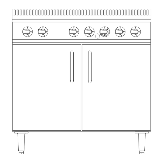
- Page 10 Specification Specification (cont.) Specification Specification 900mm Open Top Range Manual Part No: 932871-01 MD Gas Range - Page 10 of 32 – Manual Rev No: 1...
- Page 11 Specification Specification (cont.) Specification Specification 1200mm Open Top Range 1422 Manual Part No: 932871-01 MD Gas Range - Page 11 of 32 – Manual Rev No: 1...
- Page 12 INSTALLATION INSTALLATION INSTALLATION INSTALLATION Important Your attention is drawn to the latest GAS SAFETY (INSTALLATION & USE) REGULATIONS 2000. This appliance MUST be installed by a competent person in accordance with these and any other relevant regulations. Users, too, should be aware of the regulations governing the use of gas appliances, particularly with respect to the need for regular servicing.
-
Page 13: Important Note
Installation Installation (cont.) Installation Installation Important Note MUST NOT be connected DIRECTLY to a flue or ventilating system, although the flue The appliance products of two or more appliances may be directed into a common outlet when building a suite of appliances (see separate instructions for suiting appliances). -
Page 14: Checking & Commissioning
Installation Installation (cont.) Installation Installation Checking and Commissioning (cont.) ALTHOUGH EVERY APPLIANCE IS TESTED AND SET BEFORE IT LEAVES THE FACTORY, IT IS IMPORTANT THAT THE INSTALLER RE-CHECKS CERTAIN FUNCTIONS BEFORE LEAVING THE SITE. CHECK THE GAS PRESSURE AT THE APPLIANCE THUS : - The pressure test point is located on the manifold rail behind the front control panel, which is secured by screws. -
Page 15: Important Note
USERS INSTRUCTIONS USERS INSTRUCTIONS USERS INSTRUCTIONS USERS INSTRUCTIONS Important Note! GAS SAFETY (INSTALLATION & USE ) The attention of the user is drawn to the requirements of the REGULATIONS 2000 . This appliance MUST be used in accordance with those, particularly so in respect of the need for regular servicing. - Page 16 Users Instructions Users Instructions (cont.) Users Instructions Users Instructions Pan size The maximum pan size to be used is 34cm and the minimum pan size to be used is 12cm to ensure satisfactory combustion and stability Lighting Instructions: Open Hotplates To turn on an individual open top hotplate burner, push in the appropriate gas tap knob and turn it anti-clockwise to the double flame position, the “Full ON”...
- Page 17 Users Instructions Users Instructions (cont.) Users Instructions Users Instructions Keep the thermostat knob depressed for a further 20 seconds until the flame is established. If the flame is extinguished on releasing knob, wait 3 minutes then repeat steps 2 & 3. When the flame is established, turn the thermostat knob to the required setting and note the FULL ON .
- Page 18 Users Instruc Users Instructions tions (cont.) Users Instruc Users Instruc tions tions Lighting Instructions: (cont.) When setting the thermostat knob to the required temperature, turn the knob to Mark 9 (maximum) AND THEN back to the required setting. Note! Note! Note! Note! When first lighting the appliance or after installation or after an extended shut-down period, it may be necessary for gas control knob to remain pushed in for some time before burner will light, owing...
- Page 19 Users Instructions Users Instructions (cont.) Users Instructions Users Instructions Cooking identical foods on three different shelves is seldom satisfactory and is not recommended, but the “cool zone” at the oven bottom can be sometimes used for slow casseroles, whilst general and specialised cooking is carried out on the two shelves.
- Page 20 Users In Users Instructions structions (cont.) Users In Users In structions structions Cleaning the Equipment (cont.) Open Top Hotplates Wipe the open top pan support grids clean of grease and spillage’s regularly - even during cooking sessions - a crust of burned on carbon, coating the pan supports is unsightly, is a health hazard and will impair cooking efficiency.
- Page 21 Users Instructions Users Instructions (cont.) Users Instructions Users Instructions Cleaning the Equipment (cont.) The Oven DO NOT USE CAUSTIC OR ABRASIVE CLEANING AGENTS. Leave the oven drip tray in position while you clean the oven, it will collect all the bits and drips and can be removed for cleaning at the sink.
- Page 22 Users Instructions Users Instructions (cont.) Users Instructions Users Instructions General Maintenance and Care (cont.) All gas taps and gas controls must operate smoothly and freely without sticking or jerking. A QUALIFIED SERVICE ENGINEER MUST carry out re-lubrication. WE RECOMMEND THAT ALL EQUIPMENT IS SERVICED AT LEAST ONCE A YEAR, BUT MAY BE AS WE RECOMMEND THAT ALL EQUIPMENT IS SERVICED AT LEAST ONCE A YEAR, BUT MAY BE AS WE RECOMMEND THAT ALL EQUIPMENT IS SERVICED AT LEAST ONCE A YEAR, BUT MAY BE AS WE RECOMMEND THAT ALL EQUIPMENT IS SERVICED AT LEAST ONCE A YEAR, BUT MAY BE AS...
-
Page 23: Operation
SERVICE AND MAINTENANCE SERVICE AND MAINTENANCE SERVICE AND MAINTENANCE SERVICE AND MAINTENANCE MUST only be carried out by a competent person. Ensure that the gas and electricity Maintenance OFF ” before dismantling any components. supply to the appliance has been turned “ Routine Maintenance Procedure: ON ”... - Page 24 Service and Maintenance Service and Maintenance (cont.) Service and Maintenance Service and Maintenance Fault Possible Cause Remedy O O O O PEN TOP BURNER PEN TOP BURNER PEN TOP BURNER PEN TOP BURNER Burners will not stay Faulty connection at Make re-connection alight.
- Page 25 Service and Maintenance Service and Maintenance (cont.) Service and Maintenance Service and Maintenance ENSURE THAT THE GAS SUPPLY TO THE APPLIANCE HAS BEEN TURNED OFF BEFORE REMOVING OR DISMANTLING ANY GAS CONTROLS. Removal of Oven Thermostat/FFD. Remove the shelves and drip tray from the oven together with the hotplate drip tray(s). Pull off all the control knobs from the horizontal control panel, and remove by unscrewing the two fixing screws.
-
Page 26: Cleaning
Service and Maintenance Service and Maintenance (cont.) Service and Maintenance Service and Maintenance Removal of Oven Burner or Burner Injector. Remove the shelves and drip tray from inside the oven. This exposes the burner and its supply tube. The oven burner injector can be removed for cleaning, etc., without disturbing the burner. Disconnect the burner supply tube at the union on the injector elbow (immediately before the burner). - Page 27 Service and Maintenance Service and Maintenance (cont.) Service and Maintenance Service and Maintenance To Remove or clean a Open Top Burner Injector. Remove the pan supports. Remove, by lifting clear, the burner cap, ring, support (skirt) and full width drip shield. The injector can be unscrewed using a suitable socket spanner.
- Page 28 Service and Maintenance Service and Maintenance (cont.) Service and Maintenance Service and Maintenance To Convert NG Appliances to LP Gas. (Open Top) Remove the control knobs and control panel, which is secured by two fixing screws. Remove the pan supports. Remove the hotplate burner injectors as described in Section 5 and fit replacement 1.2mm LP injectors (932869-02) and re-fit burner caps etc.
- Page 29 Service and Maintenance Service and Maintenance (cont.) Service and Maintenance Service and Maintenance SPARE PARTS LIST SPARE PARTS LIST SPARE PARTS LIST SPARE PARTS LIST Part Number Description Quantity 927123-S1 Thermostat/FFD (0.55mm) (Open Top) 932329-01 Thermocouple (Oven) 1or 2 930875-02 Thermostat Knob 929344-02 Piezo Ignition Unit...
- Page 30 SPARE PARTS LIST SPARE PARTS LIST (Cont.) SPARE PARTS LIST SPARE PARTS LIST Part Number Description Quantity 932811-01 Castor swivel braked 932811-02 Castor swivel Un-braked 930735-S1 Burner Assy (900) Spares Kit 930735-S2 Burner Assy (600) Spares Kit 932948-S1 Conversion Kit NG to LPG 90R (Open Top) Spares Kit 932948-S2...
-
Page 31: Routine Maintenance
W W W W A A A A R R R R R R R R A A A A N N N N T T T T Y Y Y Y C C C C O O O O V V V V E E E E R R R R... -
Page 32: Instructions
CHECK LIST FOR 600/900 MEDIUM DUTY RANGES CHECK LIST FOR 600/900 MEDIUM DUTY RANGES CHECK LIST FOR 600/900 MEDIUM DUTY RANGES CHECK LIST FOR 600/900 MEDIUM DUTY RANGES Description Part Number Checked by DATA PLATE CONTROL KNOBS Top Burners 930875-01 Thermostat 930875-02 SHELVES 600 Ranges 924435-02 x 2...
Need help?
Do you have a question about the MV 2 Series and is the answer not in the manual?
Questions and answers