
Related Manuals for Moorwood Vulcan MV 2 SERIES


Summary of Contents for Moorwood Vulcan MV 2 SERIES
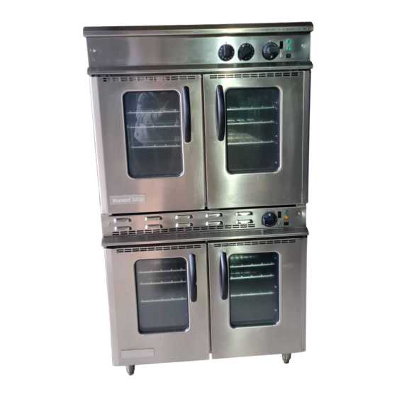
- Page 1 MV 2 SERIES GAS CONVECTION OVEN OWNER’S MANUAL Country of Destination GB and IE Manual Part No: 932971-01 MD Gas Convection Oven Page 1 of 32 Manual Rev No: 1...
-
Page 2: Manual Part No
Model No. Product Description Rev. Date Flexible Hose Size MV Gas Convection Oven MV2OCO90-1T-NG 900 Single Tier Gas Convection Oven 08/01/08 ½” BSP hose MV2OCO90-1T-NG-C 900 Single Tier Gas Convection Oven 08/01/08 ½” BSP hose On Castors MV2OCO90-1T-NG-LO 900 Single Tier Gas Convection Oven 08/01/08 ½”... -
Page 3: Table Of Contents
INDEX Page Cover Sheet: Revision Sheet: Index: Warning Sheet : Introduction: 5 & 6 General Introduction Important Note Specification: 7 - 12 Gas Pressure/Connection 7 & 8 Overall Dimensions 9 & 10 Wiring Diagrams 11 & 12 Installation: 13 - 16 Important Note Positioning 14 &... - Page 4 Manual Part No: 932971-01 MD Gas Convection Oven Page 4 of 32 Manual Rev No: 1...
-
Page 5: Introduction
INTRODUCTION This manual contains all the required information to ensure that your new appliance is installed correctly and that you have all the information necessary to identify and order spare parts. It also contains comprehensive instructions for the user and for cleaning the appliance. To maintain peak performance, it is recommended that the appliance be regularly serviced and that when ordering spare parts, reference be made to the appropriate list quoting the Part No. - Page 6 Introduction (Cont.) Important Before installing any item please refer to the installation instructions. We recommend that our authorised service agents carry out all servicing, other than routine cleaning, and will accept no responsibility for work carried out by other persons. For satisfactory operation, parts of catering equipment become hot.
-
Page 7: Specification
SPECIFICATION 900 Single Tier Gas Convection Oven 900 Two Tier Gas Convection Oven Gas Pressure Supply Pressure Adjusted Pressure Natural Gas 20 mbar ( 8” wg) 15 mbar ( 6” wg) Propane Gas 37 mbar (14.8” wg) 37 mbar (14.8” wg) Gas Connection 1/2”... - Page 8 Specification (Cont.) Burner Injectors Natural Gas Propane Gas Oven 2.44 1.51 Pilot Injector 0.75 0.26 Oven Dimensions Oven Cavity – Width 785mm Oven Cavity – Depth 530m Oven Cavity – Height 375mm Nominal Volume 0.16m (5.65ft Shelf Size 665mm x 510mm suitable for 2 off 1x1containers Volume of Cooking Space 0.12m...
- Page 9 Specification (cont.) 900mm Single Tier Gas Convection Oven Manual Part No: 932971-01 MD Gas Convection Oven Page 9 of 32 Manual Rev No: 1...
- Page 10 Specification (cont.) 900mm Two Tier Gas Convection Oven Manual Part No: 932971-01 MD Gas Convection Oven Page 10 of 32 Manual Rev No: 1...
- Page 11 Specification (cont.) Wiring Diagram: Single Tier Manual Part No: 932971-01 MD Gas Convection Oven Page 11 of 32 Manual Rev No: 1...
-
Page 12: Specification
Specification (cont.) 933161-01 Wiring Diagram: Two Tier Manual Part No: 932971-01 MD Gas Convection Oven Page 12 of 32 Manual Rev No: 1... -
Page 13: Installation
INSTALLATION Important GAS SAFETY (INSTALLATION & USE) REGULATIONS 2000. Your attention is drawn to the MUST This appliance be installed by a competent person in accordance with these and any other relevant regulations. Users, too, should be aware of the regulations governing the use of gas appliances, particularly with respect to the need for regular servicing. -
Page 14: Important Note
Installation (cont.) Positioning Place the appliance in position allowing a minimum gap of 150mm (6 ) at the rear and at least 150mm ” ) between the sides of the appliance and any adjacent wall. If the appliance is being suited then please ”... - Page 15 Installation (cont.) Gas Connection (cont.) BEFORE Ensure that all the pipes to the appliance are clean and free from swarf etc, making the final connection. EXCEPT MUST Propane Gas: Follow the same procedure as that for Natural Gas that the Gas Governor be fitted –...
-
Page 16: Installation
Installation (cont.) Checking and commissioning (cont.) Remove the cap in order to gain access to the pressure adjusting screw. Turn the pressure adjusting screw clockwise to increase the pressure or anti-clockwise to decrease it. When the pressure reading is correct, refit the cap to the governor. Turn the gas supply to the unit at the stopcock and disconnect the manometer (U Tube). -
Page 17: Important Note
USERS INSTRUCTIONS Important Note GAS SAFETY (INSTALLATION & USE) The attention of the user is drawn to the requirements of the REGULATIONS 2000 . This appliance must be used in accordance with those, particularly so in respect of the need for regular servicing. The attention of the user is also drawn to the requirement that those parts, which have been protected by the manufacturer or his agent, are not to be adjusted by the user. - Page 18 Users Instructions (cont.) Oven Green Light - Is alight when there is an electrical supply to the unit. Amber Light - Is on when the oven burner is lit. When the amber light goes out the oven has reached temperature. Ignition Switch - Initiates the ignition sequence.
- Page 19 Users Instructions (cont.) The following guide is for temperature settings. Cooking times will vary according to food weight and BUT IT WILL BE SHORTER THAN CONVENTIONAL COOKING size Cooking Guide Mark No Temp °C Temp °F ROASTING Beef joint on bone 2 or 3 140 - 160 284 –...
-
Page 20: Cleaning
Users Instructions (cont.) Cleaning the Equipment It will be found that it takes less time and effort if appliances are cleaned every day, particularly while they are still warm and before grease and spillage are burnt on. PROPRIETARY OVEN CLEANER MUST BE USED WITH CARE. THEY ARE HIGHLY CORROSIVE AND MAY CAUSE DAMAGE TO SURACES AND COMPONENTS. -
Page 21: User Instructions
Users Instructions (cont.) Cleaning the Equipment (cont.) General Maintenance and Care This equipment is designed and manufactured to give you a long, satisfactory service at low cost, provided that it is given proper care and attention at all times. Frequent cleaning and regular checking of correct adjustment will be rewarded by reduced operating and maintenance costs, minimum downtime and regular results from your cooking. -
Page 22: Service & Maintenance
SERVICE AND MAINTENANCE MUST Maintenance only be carried out by a competent person. Ensure that the gas and electricity supplies to the appliance have been Isolated before dismantling any components. Routine Maintenance Procedure Turn “ ” the oven and check that the gas pressure at the pressure test point is as stated on the Date Plate. -
Page 23: Fault Finding
Service and Maintenance (cont.) Fault Finding. FAULT POSSIBLE CAUSE REMEDY NO SPARK AT Poor or broken connections to the Remake connections or replace ELECTRODE. Electrode or damaged insulation Damaged lead Spark gap should be 3 – 4 mm Spark gap is incorrect Adjust as necessary The insulation on the electrode is Replace the electrode... - Page 24 Service and Maintenance (cont.) Fault Finding. FAULT POSSIBLE CAUSE REMEDY PILOT LIGHTS Poor or broken earth wire. Polarity Repair poor or broken wire MOMENTARILY Of live and neutral incorrect Connection. Ensure that live and AND ELECTRODE Neutral connections are correct CONTINUES TO The pilot flame is too low in height Check pilot injector size.
-
Page 25: Fault Finding
Service and Maintenance (cont.) Fault Finding. FAULT POSSIBLE CAUSE REMEDY OVEN FAILING Pilot burn down. When the oven is WHILST IN COOKING cold, the pilot flame should have a Check injector size. If partially CYCLE length of approx. 25-35mm, or blocked clean and re-fit. - Page 26 Service and Maintenance (cont.) ENSURE THAT THE GAS/ELECTRICITY SUPLY TO THE APPLIANCE HAS BEEN ISOLATED BEFORE REMOVING OR DISMANTLING ANY CONTROLS. Removal of Oven Thermostat. Remove all control knobs and control panel, secured by two M5 screws. Withdraw control panel and remove two fixing screws securing thermostat.
- Page 27 Service and Maintenance (cont.) Removing the Igniter/Sensing Electrode Assembly. Proceed as described in Section 3. Working from the rear of the appliance, remove the electric’s cover, secured by four screws. Disconnect the igniter/sensor electrode from the two-way terminal block. The electrode can now be removed from inside the oven.
- Page 28 Service and Maintenance (cont.) To Remove Fan and/or Motor. From inside the oven cavity, remove the oven shelves and the fan guard, which is secured by four fixing screws. Remove the single fixing screw securing the fan, then withdraw the fan (this can be done using the fan extractor, located at the rear of the appliance on the back panel, between the flues).
-
Page 29: Service & Maintenance
Service and Maintenance (cont.) To Convert LP appliances to NG Gas. (Single & Two Tier Ovens) Remove the oven furniture. Switch off and disconnect the supplies. Remove the oven burner (Section 2) and unscrew the injector. Remove Aeration Plate (927438-01) by drilling out the 1/8 pop rivets. -
Page 30: Spare Parts
SPARE PARTS LIST Part Number Description Quantity 930021-01 Full Sequence Controller 1 or 2 929358-01 Pressure Switch 1 or 2 930094-01 Thermostat 1 or 2 930022-01 Re-Set Switch 1 or 2 927447-01 Ignition Switch 1 or 2 926173-01 Neon - Amber 1 or 2 926173-02 Neon - Green... -
Page 31: Spare Parts
Spare Parts List (Cont.) Part Number Description Quantity 932853-01 Leg 65mm Dia 932811-01 Castor Swivel Braked 932811-02 Castor Swivel Unbraked 922088-G1 Pilot Assy NG 1 or 2 922088-G2 Pilot Assy LP 1 or 2 931897-S1 Conversion Kit NG to LPG 1 or 2 931897-S2 Conversion Kit LPG to NG... - Page 32 The Company offer twelve months warranty with each new piece of equipment subject to our normal conditions of sale and will undertake responsibility for warranty subject to the additional following conditions. Notice of the defect/damage is given within 48 hours of breakdown or in the case of damage four days from the date of despatch and the manufacturer given adequate opportunity to examine the goods in order that appropriate action can be taken.
Need help?
Do you have a question about the MV 2 SERIES and is the answer not in the manual?
Questions and answers