
Subscribe to Our Youtube Channel
Related Manuals for Revo REHSPTZ30-1


Summary of Contents for Revo REHSPTZ30-1
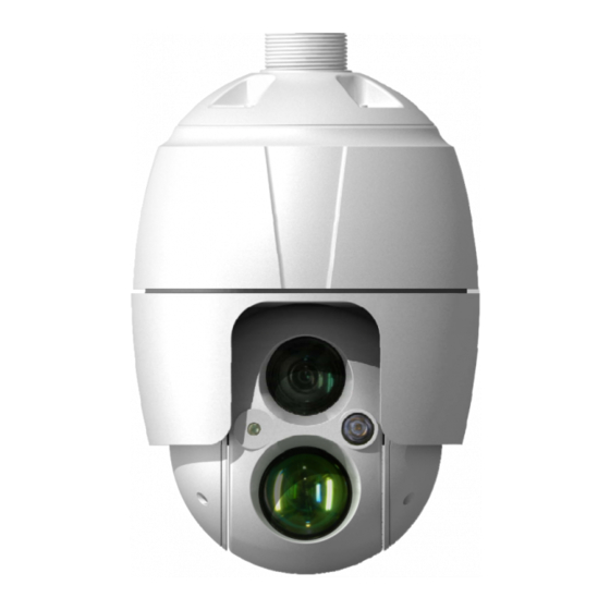
- Page 1 INSTRUCTION MANUAL REHSPTZ30-1 REVO ELITE HD 30x Full-HD IR SPEED DOME NETWORK CAMERA Please read this manual thoroughly before use and keep it handy for future reference.
-
Page 2: Explanation Of Graphical Symbols
WARNING TO REDUCE THE RISK OF FIRE OR ELECTRIC SHOCK, DO NOT EXPOSE THIS PRODUCT TO RAIN OR MOISTURE. DO NOT INSERT ANY METALLIC OBJECTS THROUGH THE VENTILATION GRILLS OR OTHER OPENINGS ON THE EQUIPMENT. CAUTION EXPLANATION OF GRAPHICAL SYMBOLS The lightning flash with arrowhead symbol, within an equilateral triangle, is intended to alert the user to the presence of uninsulated “dangerous voltage”... -
Page 3: Fcc Compliance Statement
FCC COMPLIANCE STATEMENT FCC INFORMATION: This equipment has been tested and found to comply with the limits for a Class A digital device, pursuant to Part 15 of the FCC Rules. These limits are designed to provide reasonable protection against harmful interference when the equipment is operated in a commercial environment. -
Page 4: Important Safety Instructions
IMPORTANT SAFETY INSTRUCTIONS Read these instructions. Keep these instructions. Heed all warnings. Follow all instructions. Do not use this apparatus near water. Clean only with dry cloth. Do not block any ventilation openings. Install in accordance with the manufacturer’s instructions. Do not install near any heat sources such as radiators, heat registers, stoves, or other apparatus (including amplifiers) that produce heat. -
Page 5: Table Of Contents
TABLE OF CONTENTS 1. Description ........................7 1.1 Components ......................... 7 1.2 Key Features......................... 8 2. Installation........................9 2.1 Installation ..........................9 2.2 Basic Configuration of Camera System ................12 2.3 Connections........................13 2.4 Network Connection & IP assignment ................14 3. Operation........................15 3.1 Access from a browser...................... - Page 6 2) Tour ..........................45 3) Motor Setup ........................46 4) RS485 ..........................47 5) View Angle........................47 6) System Menu ......................... 48 7) Privacy Zone........................49 3.5.7 System .......................... 50 1) Information ........................50 2) Security.......................... 50 3) Date & Time ........................52 4) Network..........................
-
Page 7: Description
1. Description The network camera supports the network service for a sensor image with progressive scan, which can be monitored on a real-time screen regardless of distances and locations. By using its dedicated program, many users are able to have an access to the network camera at once or a single user can monitor various network cameras at the same time. -
Page 8: Key Features
1.2 Key Features Brilliant video quality The network camera offers the highly efficient H.264 video compression, which drastically reduces bandwidth and storage requirements without compromising image quality. Motion JPEG is also supported for increased flexibility. Triple Streams The network camera can deliver triple video streams simultaneously at full frame rate in all resolutions up to 1920 x 1080 using Motion JPEG and H.264. -
Page 9: Installation
2. Installation 2.1 Installation You need one optional mount kit of the wall mount and the ceiling mount to install. The wall or ceiling mount must be attached to a structural object such as hard wood, concrete that will support the weight of the mount and dome camera. The use of a solid backboard is recommended when attaching to gypsum walls. - Page 10 2.1.1 Installation - Wall Mount The wall mounting plate must be attached to a structural object such as concrete that will support the weight of the mount and Dome Camera. 1. Select a suitable mounting location and verify there is sufficient cable to reach the middle of the Wall Mount.
- Page 11 2.1.2 Installation - Ceiling Mount The ceiling mounting plate must be attached to a structural object such as concrete that will support the weight of the mount and Dome Camera. 1. Select a suitable mounting location and verify there is sufficient cable to connect with cables from the housing.
-
Page 12: Basic Configuration Of Camera System
2.2 Basic Configuration of Camera System CONNECTOR COLOR DESCRIPTION DC JACK BLACK 12VDC Ethernet, RJ-45 port RJ-45 BLACK compatible with 10/100Mbps BLACK AUDIO INPUT GRAY AUDIO OUTPUT GRAY 3P Cable ALARM INPUT BLUE ALARM OUTPUT BROWN RS485+(A) 2P Cable BROWN/WHITE RS485-(B) 1P Cable YELLOW/GREEN... -
Page 13: Connections
2.3 Connections Connecting the Network Connect a standard RJ-45 cable to the network port of the camera. Generally a cross-over cable is used for directly connection to PC, while a direct cable is used for connection to a hub. ... -
Page 14: Network Connection & Ip Assignment
2.4 Network Connection & IP assignment The camera supports the operation through the network. When a camera is first connected to the network, it has no IP address. So, it is necessary to allocate an IP address to the device with the “SmartManager”... -
Page 15: Operation
3. Operation The network camera can be used with Windows® operating system and browsers. The recommended browsers are Internet Explorer®, Safari®, Firefox®, Opera™ and Google® Chrome® with Windows. NOTE: To view streaming video in Microsoft Internet Explorer, set your browser to allow ActiveX controls. -
Page 16: Access From The Internet
3.2 Access from the internet Once connected, the network camera is accessible on your local network (LAN). To access the network camera from the Internet you must configure your broadband router to allow incoming data traffic to the network camera. To do this, enable the NAT traversal feature, which will attempt to automatically configure the router to allow access to the network camera. - Page 17 1) General controls Live View Page Setup Page Help Page The video drop-down list allows you to select a customized or pre-programmed video stream on the Live View page. Stream profiles are configured under Setup > Basic Configuration > Video & Image. For more information, please see “3.5.1 Basic Configuration >...
-
Page 18: Network Camera Setup
3.5 Network Camera Setup This section describes how to configure the network camera, and is intended for product. Administrators, who have unrestricted access to all the Setup tools; and Operators, who have access to the settings for Basic Configuration, Live View, Video & Image, Audio, Event, Dome Configuration, System You can configure the network camera by clicking Setup in the top right-hand corner of the Live View page. -
Page 19: Users
1) Users User access control is enabled by default. An administrator can set up other users, by giving these user names and passwords. It is also possible to allow anonymous viewer login, which means that anybody may access the Live View page, as described below: The user list displays the authorized users and user groups (levels): User Group Authority... -
Page 20: Network
2) Network The network camera supports both IP version 4 and IP version 6. Both versions may be enabled simultaneously, and at least one version must always be enabled. When using IPv4, the IP address for the network camera can be set automatically via DHCP, or a static IP address can be set manually. -
Page 21: Video & Image
3) Video & Image Sensor Setting: - Capture mode: Use can select video frame rate at either 60/50fps or 30/25fps of resolution 1920x1080. Stream 1 Setting: - Codec: The codec settings are separated into H.264. H.264 is also known as MPEG-4 Part 10. - Page 22 Users can reset the selected screen size anytime while monitoring the screen on a real- time basis. - Bit rate control: Limiting the maximum bit rate helps control the bandwidth used by the H.264 video stream. Leaving the Maximum bit rate as unlimited maintains consistently good image quality but increases bandwidth usage when there is more activity in the image.
-
Page 23: Audio
4) Audio The network camera can transmit audio to other clients using an external microphone and can play audio received from other clients by attaching a speaker. The Setup page has an additional menu item called Audio, which allows different audio configurations, such as full duplex and simplex. -
Page 24: Date & Time
5) Date & Time Current Server Time: This displays the current date and time (24h clock). The time can be displayed in 12h clock format in the overlay (see below). New Server Time: Select your time zone from the drop-down list. If you want the server clock to automatically adjust for daylight saving time, select “Automatically adjustment for daylight saving time changes”. -
Page 25: Live View
3.5.2 Live View Video Input Mode: - Video Mode: Choose Video Mode you wish to use from the drop-down list: NTSC or PAL 3.5.3 Video & Image 1) Basic Refer to “3.5.1 Basic Configuration > Video & Image” for more details. -
Page 26: Image
2) Image Image Appearance: - Brightness: The image brightness can be adjusted in the range 1 ~ 12, where a higher value produces a brighter image. - Sharpness: Controls the amount of sharpening applied to the image. A sharper image might increase image noise especially in low light conditions. -
Page 27: Auto Exposure
3) Auto Exposure Auto Exposure Setting: Exposure is the amount of light detected by the camera sensor. A scene with correct exposure settings has adequate detail and contrast between white and dark values. An image with too little or too much exposure may lose detail in the scene. The camera features Auto and Manual Exposure Settings. - Page 28 WDR Control: Wide Dynamic Range (WDR) improves video exposure quality in scenes with high contrast between bright and dark areas, for example, if a shady area and a bright light area are in the same scene. - Mode: Select On or Off. ...
-
Page 29: Day & Night
4) Day & Night Day & Night Control: Select the day & night mode from among three modes. - Mode: * Automatic: Normally displays color image, and switches automatically to black & white image after the ambient light level reaches a pre-defined threshold. * Day: Always displays color image. -
Page 30: Auto Focus
- Off level: Specify the illumination level that deactivates the IR mode. If the illumination is above the specified level, the indicator will turn off. (31 ~ 99) - Fixed IR Bright: Specify the bright of the Fixed IR illuminator. (0 ~ 4) - Moving IR Bright: Specify the bright of the Moving IR illuminator. -
Page 31: Dis
6) DIS Digital Image Stabilization Setting: Controls DIS level from 0 to 9 and usage of 4 suppress: Local motion, Illumination, Plain background, and Slow motion. 7) Webcasting The network camera can stream live video to a website. Copies the HTML code generated on the screen and pastes it in page code of the website you want to display live video. -
Page 32: Audio
3.5.4 Audio Refer to “3.5.1 Basic Configuration > Audio” for more details. 3.5.5 Event 1) Event In On Boot This is used to trigger the event every time the network camera is started. Select “Enable” to activate the motion event. - Page 33 Alarm In This page allows you to configure the input supported by the camera. The Port can be given as Normally Open or Normally Close state, and their Normal state can be configured. An input will be inactive as long as its Normal state equals its Current state. The 2 options for Normal state are NO (Normally Open) and NC (Normally Close).
- Page 34 Manual Trigger This option makes use of the Manual Trigger button provided on the Live View page, which is used to start or stop the event type manually. Alternatively, the event can be triggered via the product's API (Application Programming Interface). ...
- Page 35 Pre-Viewer: Motion detection windows are configured by Motion or Mask windows. Each window can be selected by clicking with the mouse. It is also possible to resize, delete or move the window, by selecting the appropriate window at the mouse menu on the video screen.
-
Page 36: Event Out
Tampering This is used to trigger the event when camera tampering occurs. Select “Enable” to activate the Tempering event. 2) Event Out SMTP (E-Mail) The network camera can be configured to send event and error email messages via SMTP (Simple Mail Transfer Protocol). - Page 37 - Mail Server/Port: Enter the host names (or IP addresses) and port numbers for your mail server in the fields provided to enable the sending of notifications and image email messages from the network camera to predefined addresses via SMTP. - Sender: Enter the email address to be used as the sender for all messages sent by the network camera.
- Page 38 NOTE: A DNS server must be specified in the TCP/IP network settings if using a host name. - Port: Enter the port number used by the FTP server. The default is 21. - Use passive mode: Under normal circumstances the network camera simply requests the target FTP server to open the data connection.
- Page 39 HTTP Server Setting: - Name: The name of the HTTP event server. Use a descriptive name. - URL: The network address to the server and the script that will handle the request. For example: http://192.168.12.244/cgi-bin/upload.cgi - User name/Password: Provide your log-in information. ...
- Page 40 Audio Alert When the network camera detects an event, it can output predefined audio data to an external speaker. Check the box to enable the service. Audio Alert Setting: To use the Audio Alert with the network camera, an audio data file made by the user must be uploaded from your PC.
- Page 41 PTZ Preset When the camera detects an event, you can move the camera to a predefined preset position. Check the box to enable the service and return to the Home position once the event has ended. Event Notification When the network camera detects an event, Notification server is used to receive notification messages as a type of XML data format.
-
Page 42: Event Map
Boost The Boost feature is used in conjunction with event detection. When this feature is turned ON, the Frame rate and Bit rate in the boost condition can be set to a different value than the ones in the normal condition field. When an event is detected, the camera will boost the Frame rate and Bit rate from the normal condition to this boosted level for the duration of the event. - Page 43 The event map allows you to change the settings and establish a schedule for each event trigger from the network camera. You can register the event map up to max. 15. Click the Add button to make a new event map: a popup window display as below. •...
-
Page 44: Dome Configuration
3.5.6 Dome Configuration 1) Preset If you need to view specific places routinely, you should program Presets. A Preset is a programmed video scene with automatic pan, tilt, zoom and focus settings. Once programmed, clicking the Preset number or clicking the Go button in the PTZ Control Panel calls up that Preset automatically. -
Page 45: Tour
2) Tour There are 8 programmable Tours. Each Tour consists of up to 100 Presets. • Tour Setting: - Tour Number: The Tour number can be selected in the range 1 - 8. - Title: Up to 12 characters (Alphanumeric characters and space) - Repeat: Select number of repetition from Continuous to 90. -
Page 46: Motor Setup
- Delete Position: If you want to remove Tour position from Tour Position Setup list, select the desired Tour Position, and click the Delete Position button. - Set Position: Click the Set Position button, then show the stored Presets or Home on drop-down list. -
Page 47: Rs485
4) RS485 • RS485 Setting: - DOME ID: Enter identification number for external PTZ device. The DOME ID can be adjusted in the range 1 ~ 3999. - Protocol: Selects PTZ protocol to communicate with external PTZ device. - Baud rate: Selects one of the Baud rate. - Parity: Selects one of the Parity bit. -
Page 48: System Menu
- Flip: * Off: The dome camera moves until 90 vertically. * Auto: When the camera reaches the floor directly a bove the moving object, it will stop. At that time, release the Joystick instantly and pull it down again to run the auto-flip function. -
Page 49: Privacy Zone
7) Privacy Zone Using privacy zone s (masks), you can hide up to 8 unwanted scenes in a camera. The color of privacy zones is gray. • Privacy Zone Setting: Following steps below to configure the privacy zones; 1. After aiming the camera (view direction and lens control) by using the Arrow and Zoom button in PTZ Control Panel, click Set cell of Set column at any inactive row to create privacy zone. -
Page 50: System
3.5.7 System 1) Information You can enter th e system information. This page is very useful when you require device information after installation. • Device Name Configuration: Enter the device name. • Location Configuration: Enter the location information. You can enter up to four locations. 2) Security ... - Page 51 • User List Setting: This section shows how to register a user account. Enter a user nam and password to be added, and register them by pressing the Add button. You will s the pop-u p window as below. HTTPS For greater security, the network camera can be configured to use HTTPS (Hypertext Transfer Protocol over SSL (Secure Socket Layer)).
-
Page 52: Date & Time
P Filtering Checking the Enable IP address filtering box enables the IP address filtering function. Up to 256 IP address entries may be specified (a single entry can contain multiple IP addresses). Click the Add button to add new filtered addresses. When the IP address filter is enabled, addresses added to the list are set as allowed or denied addresses. -
Page 53: Network
• New Server Time: Select your time zone from the drop-down list. If you want the server clock to automatically adjust for daylight saving time, select “Automatically adjustment for daylight saving time changes”. From the Time mode section, select the preferred method to use for setting the time: - Synchronize with computer time: Sets the time from the clock on your computer. - Page 54 - Use the following IP address: To use a static IP address for the network camera, check the radio button and then make the following settings: * IP address: Specify a unique IP address for your network camera. * Subnet mask: Specify the mask for the subnet the network camera is located on. * Default router: Specify the IP address of the default router (gateway) used for connecting devices attached to different networks and network segments.
- Page 55 DDNS • Internet DDNS (Dy namic Domain Name Service): When using the high-speed Internet with the telephone o r cable network, users can operate the network camera even on the floating IP environment in which IPs are changed at every access. sers should receive an account and password by visiting a DDNS service like tp://www.dyndns.com/ or http://www.cctv-network.co.kr/.
- Page 56 RTP sers can configure settings for sending and receiving audio or v ideo on a real-time basis. These settin gs are the IP address, port number, and Time-To-Live value to use for t ia stream(s) in multicast H.264 format. Only certain IP addresses and port numbers shou ld be used for multicast streams.
- Page 57 UPnP The network camera includes support for UPnP™. UPnP is enabled by default, and the network camera is then automatically detected by operating systems and clients that support this protocol. NOTE: UPnP must be installed on your workstation if running Windows XP. To do this, open the Control Panel from the Start Menu and select Add/Remove Programs.
- Page 58 QoS Quality of Service (QoS) provides the means to guarantee a certain level of a specified resource to selected traffic on a network. Quality can be defined as a maintained level of bandwidth, low latency, and no packet losses. The main benefits of a QoS-aware network are: - The ability to prioritize traffic and thus allow critical flows to be served before flows with lesser priority.
- Page 59 A broadband router allows devices on a private network (LAN) to share a single connectio to the Internet. This is done by forwarding netwo rk traffic from the private network to the “outside,” that is, the Internet. Security on the priv ate network (LAN) is increased since most oadband routers are pre-configured to stop attempts to access the private network (LAN) m the public network/Internet.
- Page 60 Zeroconfig Zeroconfig allows the network camera to create and assign the IP address for network cameras and connect to a network automatically. ro configuration networking (zeroconf) is a set of techniques t hat automatically creates a able Internet Protocol (IP) network without manual operator intervention or special conf iguration servers.
-
Page 61: Language
Bonjour The network camera includes support for Bonjour. When enabled, the network camera is automatically detected by operating systems and clients that support this protocol. NOTE: Bonjour - Also known as zero-configuration networking, Bonjour enables devic es to automatically di scover each other on a network, without having to enter IP addresses or configure DNS servers. -
Page 62: Maintenance
6) Maintenance • Maintenance: - Restart: The unit is restarted without changing any of the settings. Use this method if the unit is not behaving as expected. - Reset: The unit is restarted and most current settings are reset to factory default values. The settings that are not affected are: * the boot protocol (DHCP or static) -
Page 63: Support
7) Support The support page provides valuable information on troubleshooting and contact information, should you require technical assistance. • L ogs: The network camera supports system and event log information. Click the System g button to get the system log data or the Event Log button to get information on events. - Page 64 - Networks Check: Click the Network Check button to get the information about the camera’s network setting and traffic. You can see the pop-up window below. - Hardware Check: Click the Hardware Check button to diagnose the camera’s hardware like video.
-
Page 65: Help
3.6 H The Help inf ormation window will be provided as a popup window so that users can open and re it without needing to log-in. It will offer a description of the setting and Help page so that users can manipulate the network camera without a reference to the manual. -
Page 66: Appendix
4. Appendix 4.1 Troubleshooting Troubleshooting if problems occur, verify the installation of the network camera with the instructions in this manual and with other operating equipment. Isolate the problem to the specific piece of equipment in the system and refer to the equipment manual for further information. Problems/Symptoms Possible Causes or Corrective Actions The camera cannot be... -
Page 67: Alarm Connection
4.2 Alarm Connection he following connection diagram gives an example of how to connect a network camera. .3 Preventiv e Maintena Preventive maintena nce allows d etection and correction of minor that faults before they become erious and cause e quipment fai lure. -
Page 68: Product Specification
4.4 Product Specification 30x Full-HD IR SPEED DOME NETWORK CAMERA MODEL IMAGE Image Sensor 1/2.8” SONY Exmor CMOS 4.3mm ~ 129.0mm Lens 30x A/F Optical Zoom, 16x Digital Zoom Scanning Mode Progressive Scan Min. Illumination Color: 0.5Lux, B/W: 0.1Lux AE/AWB D&N True D&N (IR-cut filter) Synchronized IR LED &... - Page 69 NETWORK Max. Connections IPv4/IPv6, Manual, TCP/IP, UDP, HTTP, RTP, RTSP, Protocols NTP, DHCP, SMTP, DDNS, HTTPS, RTCP, FTP, Bonjour NAS Support JPEG push DDNS Remote Client Web browse r, SmartManager, N CTitanium Installation Tool SmartManager, NCTitanium MISCELLANEOUS Weatherproof IP66 12VDC ± 10% Power Power Consumption A (36W...
-
Page 70: System Requirement For Web Browser
.5 System Requirement for Web Browser Operating Syst em: Microsoft Windows OS Series CPU: In tel Core 2 Duo 2Ghz or higher , 1GB RAM or more, 10GB free disk or higher VGA: AGP, Video RAM 32MB or higher (1024x768, 24bpp or higher) .6 General Performance Considera tions... - Page 71 REVO ELITE HD 30x Full-HD IR SPEED DOME NETWORK CAMERA Rev.A...
Need help?
Do you have a question about the REHSPTZ30-1 and is the answer not in the manual?
Questions and answers