Table of Contents
Advertisement
HEATING DIVISION
Winterhay Lane
Ilminster, Somerset TA19 9PQ
Tel: 01460 53535 Fax: 01460 52341
Every effort is made to ensure accuracy at time of going to press. However as part of our policy of continual product improvement, we reserve the right to alter specifications without prior notice.
Supplied By www.heating spares.co Tel. 0161 620 6677
BSI Registered Firm
FM 414
Ind. & Comm. Air Heaters;
Air Moving Equipment;
Flues & Chimneys; Natural
Smoke & Heat Ventilators;
Powered Supply & Extract
Fans & Systems.
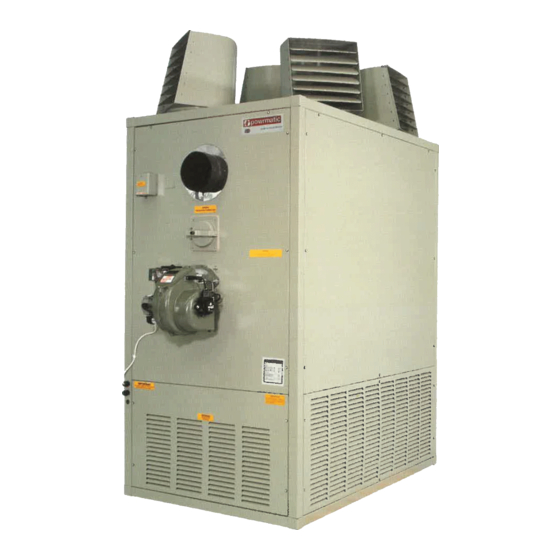
T h e CA-G R a n g e
Installation and Servicing
Instructions
W ARNING: THIS APPLIANCE MUST BE EARTHED
CE
Advertisement
Table of Contents

Related Manuals for Powrmatic CA-G series


Summary of Contents for Powrmatic CA-G series
- Page 1 T h e CA-G R a n g e Installation and Servicing Instructions BSI Registered Firm W ARNING: THIS APPLIANCE MUST BE EARTHED FM 414 Ind. & Comm. Air Heaters; Air Moving Equipment; Flues & Chimneys; Natural Smoke & Heat Ventilators; HEATING DIVISION Powered Supply &...
-
Page 2: Table Of Contents
Section Title Page Introduction Technical Data General Requirements Installation Air Distribution System Commissioning & Testing Servicing Connections to Powrmatic External Controls Fault Finding Short List of Parts Tables Title Page Dimensions (S.I. Units) Dimensions (Imperial Units) Specifications (S.I. Units) Specifications (Imperial Units) -
Page 3: Introduction
1. INTRODUCTION Gas Safety (Installation & Use) Regulations 1994 Supplied By www.heating spares.co Tel. 0161 620 6677... -
Page 4: Technical Data
2 Technical Data 2.1 Dimensions CA-G 400 - 2000 UF & UD Models FRONT SIDE FRONT SIDE CA-G 400UF SHOWN CA-G 800UF SHOWN CA-G 100 - 2000 CF & HD Models CA-G 800HD SHOWN CA-G 200HD SHOWN CA-G 800CF SHOWN Supplied By www.heating spares.co Tel. -
Page 5: A. Dimensions (S.i. Units)
Table 1a. Dimensions (S.I. Units) D #1 D #2 CA-G 100 1645 1390 CA-G 150 1822 1530 CA-G 200 CA-G 300 2076 1080 1810 CA-G 400 1060 2356 1035 2058 CA-G 500 CA-G 600 1568 1010 1873 1055 1562 1468 CA-G 700 CA-G 800 2025... -
Page 6: B. Specifications (Imperial Units)
0.62 1.00 10.0 15.0 2"BSP 7281 Table 3.1 Burner Pressures - Natural Gas - Group H - G20 - Net CV (H ) = 34.02MJ/m³ Powrmatic Burners Riello Burners Gas Rate Start Gas Main Burner Start Gas Main Burner Pressure... -
Page 7: General Requirements
Table 4 Electrical Loadings Standard Larger Horsepower Motor NOM. PLATE START FUSE NOM. PLATE START FUSE RUN AMPS MODEL MOTOR AMPS AMPS RATING MOTOR AMPS AMPS AMPS RATING R.P.M. R.P.M. CA-G 100 1000 CA-G 150 1500 10.0 CA-G 200 CA-G 300 1000 18.0 CA-G 400... - Page 8 3.4 Flue System Low Level (inlet) High Level (outlet) 3.6 Air Distribution System 3.5 Air Supply 3.7 Electrical Supply Supplied By www.heating spares.co Tel. 0161 620 6677...
-
Page 9: Installation
4.3 Connection of Air Heater(s) to Flue 4. Installation of Air Heater(s) System 4.1 General For flue sizes refer to Tables 1a Before installation, check that the local distribution condi- and 1b Page 4 tions, nature of gas and pressure, and adjustment of the appli- ance are compatible. -
Page 10: Air Distribution System
Table 2a & 2b (Page5). 5. Air Distribution System 5.1 General 6.4 Lighting the Air Heater 6.4.1 Gas Controls Assembly - Soundness Check 5.2 Noise Reduction 6.4.2 Sequence Check closed 5.3 Room Thermostat Siting 6.4.3 Final Adjustment For electrical connections of external controls see the 6.4.3.1 CA-G 100 - 300 accompanying wiring diagram. - Page 11 (Refer to the Burner Supplement) (Fig 2c - 3). (Refer to the 6.4.3.2 CA-G 400 - 2000 Burner Supplement) IMPORTANT: (Fig 2c - 4) 6.4.4 Final Soundness Test 6.4.5 Flame Safeguard 6.5 Handing over the Air Heater (Fig 2c - 5). Gas Controls Schematics Fig 1a CA-G 100 - 300 1st Main Gas...
-
Page 12: A. Gas Controls Layout Ca-G 100, 150
Fig 2a Gas Controls Layout CA-G 100, 150 1st Main gas safety shut off valves. 2nd Main gas safety shut off valves. Main burner pressure adjustment screw. Notes:- Electrical connection plugs not shown. Gas Inlet To Burner Fig 2b Gas Controls Layout CA-G 200, 300 Main gas safety shut off valves. -
Page 13: Servicing
7.5.2 Gas Controls Assembly 7.5.2.1 CA-G 100, 150 7.5.2.1.1 Gas Valve Coil. 7. Servicing 7.5.2.1.2 Block Valve Assemby. WARNING: NOTE: 7.5.2.2 CA-G 200, 300 7.5.2.2.1 Block Valve Assembly. 7.1 General 7.2 Burner Maintenance 7.5.2.3 CA-G 400 - 2000 Note: 7.3 Heat Exchanger Cleaning 7.5.3 Main Fan Motor(s) Rear Flued Heaters only 7.5.3.1. -
Page 14: Honeywell L4064N
7.5.4 Main Air Fan(s) Fig 4 Honeywell L4064N Note: Set Point Dial Fan Circuit Limit Circuit 7.5.4.1. CA G100 - CA G400 Note: (Refer to Wiring Diagram supplied with the heater) Summer / Winter Switch Limit Reset Fan Circuit Limit Circuit 7.5.4.2. -
Page 15: Connections To Powrmatic External Controls
7.5.5.3 CA-G 500 - CA-G 2000 - High Limit Thermostat. 8. Connections to Powrmatic External Controls 8.1 Powrtrol CA-G connect to Powrtrol Terminals Terminals 8.2 Eurotrol CA-G connect to Eurotrol Terminals Terminals CTRL CCT CTRL CCT FAN CCT FAN CCT... -
Page 16: Short List Of Parts
10. Short List of Parts ITEM APPLICATION PART NUMBER Johnson Controls GM-7742-3503 - ½"BSP. 100,150, 400 - 2000 141379957 Johnson Controls GM-2540-2000 - ¾"BSP. 200 - 600 141379954 Johnson Controls GM-2040-2000 - 1"BSP. 700 - 800 141379955 Johnson Controls GM-4540-3000 - 1½"BSP. 1000 - 2000 141379967 Thermostat - Fan / Limit...
Need help?
Do you have a question about the CA-G series and is the answer not in the manual?
Questions and answers