Advertisement
CE
CP Range
Users, Installation & Servicing Instructions
Gas & Oil Fired Heaters
TESTED
Full mechanical, construction, assembly and electrical sequence check
Full functional test in accordance with Quality System Procedures
Heater Model
Heater Serial No.
Fuel Type
WARNING: THIS APPLIANCE MUST BE EARTHED
CP(2007) Range Issue 3.5 July 2009
Advertisement
Table of Contents

Related Manuals for Powrmatic CP series


Summary of Contents for Powrmatic CP series
- Page 1 CP Range Users, Installation & Servicing Instructions Gas & Oil Fired Heaters TESTED Full mechanical, construction, assembly and electrical sequence check Full functional test in accordance with Quality System Procedures Heater Model Heater Serial No. Fuel Type WARNING: THIS APPLIANCE MUST BE EARTHED CP(2007) Range Issue 3.5 July 2009...
- Page 2 7. Powrmatic ‘General Conditions of Sale’ have been observed. 8. Except for the obligation of Powrmatic Ltd to perform warranty repairs during the guarantee period, Powrmatic will not be liable in respect of any claim for direct or indirect consequential losses, including loss of profits or increased costs arising from loss of use of the appliance, or any event arising there from.
- Page 3 Users Instructions 1. Checks before lighting the Air Heater will automatically start. When the external controls are satisfied the burner will be turned off and approximately 4/5 minutes The following checks should be made before lighting the heater(s) later the heater fan will automatically stop. a) Ensure the electrical supply to the heater is switched OFF.
- Page 4 All Powrmatic heaters use gas and electricity to power them, they may also contain moving parts such as pulley belts. It would be hazardous to tamper with or attempt to service unless you are a competent person in the field of Gas and Electrical work.
-
Page 5: Table Of Contents
Installation & Servicing Instructions Index Section Title Page Introduction Technical data General requirements Installation of air heater(s) Commissioning & testing Servicing Fault finding Short list of parts Appendix A Table Title Page Dimensions Specifications Electrical Data Burner Pressures for Natural Gas - Groupe H – Type G20 Burner Pressures for Propane –... -
Page 6: Introduction
Installation & Servicing Instructions 1. INTRODUCTION The Powrmatic CP range of closed flue, fanned circulation air heaters cover a heat output range of 29.3 kW to 586.1 kW and are intended primarily for heating commercial or industrial premises. They are fitted with either a gas fired forced draught b u r n e r o r a p r e s s u r e j e t o i l f i r e d b u r n e r. -
Page 7: Technical Data
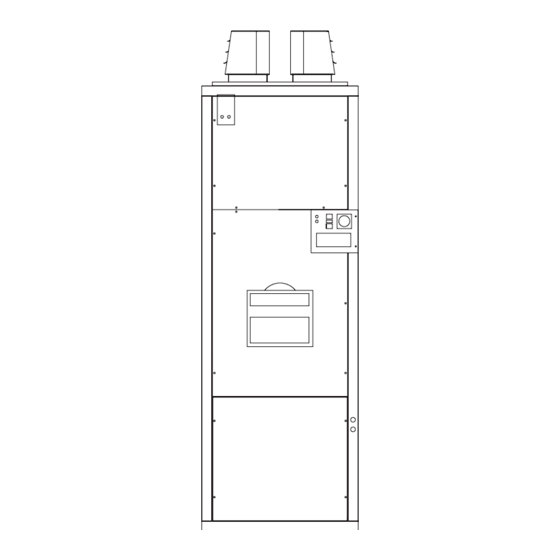
2. TECHNICAL DATA CP 100 - 1250 Standard Style (CP300 Shown) width length height width Front View Side View Rear View as /UF as /UF as /UD (with optional inlet duct spigot) width height Front View Plan View as /HF as /HD (with optional inlet duct spigot) /EA Style... - Page 8 /EA Style continued (CP300/EA Shown) Top View as /UD height width height width LH Side View Front View RH Side View as /SD as /SD as /SD (with fresh air inlet louvre) (with return air inlet duct spigot) /NCA Style (CP300/NCA Shown) width length...
-
Page 9: Dimensions
Table 1. Dimensions Model Connection Connection NCA& EA Size Size CP100 1130 600 1644 304 1386 125 0.5” CP150 For CPO150 see CP100 above, for CPG150 see CP200 below (For /E variant CPG150 see CPG100) CP200 1255 626 1822 1553 125 CP300 1307 2074... - Page 10 0.75 43.78 CP-G 1500 RS 50 0.75 54.00 CP-G 2000 GAS 5 Refer to Powrmatic 71.82 Table 4.2 Burner Pressures - Propane Gas - G31 - Net CV (H ) = 88.0MJ/m³ Riello Burners Start Gas Main Burner Model Type...
-
Page 11: General Requirements
3. General Requirements 3.2 Oil Fired Heaters 3.2.1 Related Documents 3.1 Gas Fired Heaters The installation of the air heater(s) must be in accordance with 3.1.1 Related Documents the rules in force and the relevant requirements of the Building The installation of the air heater(s) must be in accordance with Regulations and the I.E.E. -
Page 12: Installation Of Air Heater(S)
Advice in these or flooded or in any position adjacent to an extraction system instances may be obtained from Powrmatic Ltd. which is carrying flammable vapour. In areas subjected to significant negative pressures due to Grilles or louvres should be so designed that high velocity air extract systems. -
Page 13: Electrical Connections
4.7 Electrical Connections 540 cm² plus 4.5 cm² per kilowatt in excess of 60 kW total rated input. Wiring external to the air heater must be installed in accordance (b) High Level (outlet) with the I.E.E. Regulations for Electrical Installations and any for heaters of total rated heat input less than local regulations which apply. - Page 14 If necessary suitable barrier rails should be provided to prevent any combustible material being placed within 900mm of the outlets. Joints and seams of supply ducts and fittings must be securely fastened and made airtight. It is recommended that ducting should be connected to the heater spigots via an airtight flexible coupling of noncombustible material.
-
Page 15: Commissioning & Testing
Commissioning & Testing 1. Remove the sealing screw from the pressure test point located on the side of the gas inlet to the burner head and attach a pressure gauge. Remove the sample point cover plug from the Electrical Installation outlet flue length and insert a CO measuring instrument. - Page 16 1. The max. air pressure switch must be set after all other adjustments have been made. 2. Begin with the switch at its highest setting and the burner working at the correct input for high fire. 3. Slowly adjust the pressure switch dial anti-clockwise, to decrease the set point, until the burner locks out.
-
Page 17: Servicing
Servicing ensure that the fan direction of rotation corresponds with the direction of rotation arrow on the fan guard or case. If necessary WARNING: Always switch off and disconnect electricity supply, reverse the direction of rotation by interchanging any two of close the gas service valve or turn off the oil supply before the motor live leads at the terminal strip in the electrical panel. -
Page 18: Thermostat Fan / Limit - Honeywell L4064N
Fig 4 Thermostat Fan / Limit - Honeywell L4064N Mechanical Limiter Set Point Dial Release Point Mechanical limiter Limit Setpoint Adjustment Limit Circuit Fan ON Setpoint Adjustment Fan Circuit Fan OFF Setpoint Adjustment Fan ON Override Limit Reset Fan Circuit Jumper Location Limit Circuit Note: The new L4064N may be supplied with the limit... -
Page 19: Fault Finding
9. Fault Finding Refer also to the burner supplement supplied with the heater Fault Cause Action Main burner will not light Electrical 1. Check electrical supply is ON. 2. Check controls are ON or calling for heat. 3. Faulty burner control unit. 4. -
Page 20: Appendix A
Appendix A Calculation Of Flue System Equivalent Resistance The pressure resistance of the flue system (Pr) can be calculated from Pr = 1.5 * [(PFF*H/D+SRF)Qm/Wm2] Where Pr = Pressure resistance of the flue system in pa PRF = Pipe Friction Factor H = Effective flue height in m D = Internal Diameter of flue in m SRF = Sum of individual resistance factors...
Need help?
Do you have a question about the CP series and is the answer not in the manual?
Questions and answers