Table of Contents
Advertisement
Safety, Operation and Maintenance Manual
Important Information and Safety Instructions
Register your Machine at www.jondon.com
Serial No:
© 2013 Copy Rights Reserved Jon-Don, Inc.
with Parts List
Please read before use!
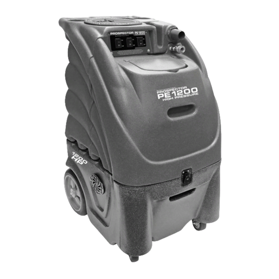
Model No. PE1200
1200 PSI
REGISTER
YOUR
MACHINE
ONLINE!
Reliable Power
Innovative Design
Safe & Easy to Use
Powerful Extracting
Easy Transport
Patented Features
Advertisement
Table of Contents

Related Manuals for Jon-Don PE1200


Summary of Contents for Jon-Don PE1200
- Page 1 YOUR MACHINE ONLINE! Model No. PE1200 Reliable Power Innovative Design Safe & Easy to Use Important Information and Safety Instructions Powerful Extracting Register your Machine at www.jondon.com Easy Transport Serial No: Patented Features © 2013 Copy Rights Reserved Jon-Don, Inc.
-
Page 2: Table Of Contents
Operating Manual Table of Contents Warranty Policy ..............................2 1.0 Safety Instructions ............................3 2.0 Grounding Instructions ..........................3 3.0 Prepare Unit for Use ............................. 4 3.1 Automatic Chemical Feed ........................5 3.2 Pressure Pump System ..........................5 3.3 Vacuum System ............................6 4.0 Set-Up and Operating ........................... -
Page 3: Warranty Policy
The Machine Registration Form must be completed online at the time of purchase. If proof of purchase cannot be identified, the warranty start date is ninety (90) days after the date of sale to an authorized Jon-Don, Inc. -
Page 4: Safety Instructions
1.0 Safety Instructions READ THIS MANUAL BEFORE USING YOUR HARD SURFACE EXTRACTOR. KNOW THE PROPER OPERATION, CORRECT APPLICATIONS AND THE LIMITATIONS OF THIS EQUIPMENT BEFORE USE. Reduce the Risk of Fire, Electric Shock or Injury: • Use only as described in this manual. Use only the attachments recommended by the manufacturer. •... -
Page 5: Prepare Unit For Use
2.0 Grounding Instructions Continued Grounding Method The electric Carpet Extractor is for use on a normal 120 volt circuit. It has a grounded plug that fits the outlet illustrated in Figure A. If a properly grounded outlet is not available, a temporary adapter, such as the adapter illustrated in Figure B and C, may be used to connect the plug into a 2-pole outlet, as shown in Figure C. -
Page 6: Automatic Chemical Feed
3.0 Prepare Unit for Use Continued Automatic Chemical Feed Continued Liquid Concentrates: the Hard Surface Extractor comes with the orange metering tip installed at the factory. This tip is rated for a 0.4 oz. of chemical per gallon of water, which is a standard dilution ratio for the most popular liquid cleaning products on the market. -
Page 7: Vacuum System
Clean or replace hose and/or filter and repeat the priming process. If you are having trouble with the pump, refer to the “Trouble Shooting Guide” section or contact the Jon-Don technical support team for advice or assistance. -
Page 8: Set-Up And Operating
4.0 Set-Up and Operation Electrical Cords Two (2) 25-foot power cords are supplied with your Hard Surface Extractor. Cord 1 powers both vacuum motors and Cord 2 powers the high pressure solution pump and waste pump. The amperage required by each cord requires that the two (2) cords be plugged into separate circuits. -
Page 9: Connection Of Solution Hose
4.0 Set-Up and Operation Continued Water and Chemical Dilution – Auto Fill Continued Metering Tip Kit The Metering Tip Kit contains 14 different colored metering tips, allowing dilution rates from 11:1 up to 427:1. Refer to the chart below to select the tip that meets the dilution rate for your chemical application. •... -
Page 10: Power Priming The High Pressure Pump
Clean or replace hose and/or filter and repeat the priming process. If you are having trouble with the pump, refer to the “Trouble Shooting Guide” section or contact the Jon-Don technical support team for advice or assistance. -
Page 11: Connection Of Auto-Dump Hose
4.0 Set-Up and Operation Continued Optional In-Line Filter An optional in-line filter (OE-ILF-EA) can be purchased and is recommended for use with all jobs. Short Vacuum Hose with Cuffs Vacuum Hose 1-1/2” x 25-Foot with 2” and 1-1/2” Cuffs Connection of Auto-Dump Hose The auto-dump hose is a 50-foot section of a 3/4”... -
Page 12: Adjusting The Pressure
4.0 Set-Up and Operation Continued Connection of Auto-Dump Hose Continued If the auto-dump or vacuum shut-off is not working properly, refer to the “Trouble Shooting Guide” section or contact your distributor for advice or assistance. Float Assembly Part No. 80-0012 Drain Recovery Tank Adjusting the Pressure When the high pressure solution pump is on and primed, pressure will show on the gauge only while the tool is being... -
Page 13: Switch Panel
4.0 Set-Up and Operation Continued Switch Panel Vacuum 1 – Power from Solution Pump Switch – Cord 1 Power from Cord 2 When the switch is turned to the ON When the switch is turned to the position, power is supplied to the ON position, power is supplied vacuum motor (3-Stage Vacuum). -
Page 14: Shutdown Procedures
5.0 Shutdown Procedures • If using the auto-fill system, turn the water supply OFF before finishing each job. This will allow use of the water and chemicals already in the tank and will reduce the amount of excess water to be disposed of later. •... -
Page 15: Maintenance
6.0 Maintenance Continued Clean Chemical Feed Filter Filter and Foot Valve The filter is on the end of the chemical feed hose that is placed in the chemical jug as part of the chemical feed system. Regularly examine the filter and clean as needed. Chemical Feed Hose Clean Chemical Feed Foot Valve The foot valve is on the end of the chemical supply tube of the automatic chemical feed system. -
Page 16: Clean Auto-Dump Pump-Out
6.0 Maintenance Continued Clean Auto-Dump Pump-Out The auto-dump pump-out system is capable of handling most debris that passes through the waste filter. However, for optimum performance, keep the recovery tank clean and remove debris from the filter screen of the auto-dump pump-out. This should be done on a daily basis or as needed, depending upon use and amount of debris. - Page 17 6.0 Maintenance Continued Flush Solution Tank and Pump Continued • Pour two (2) or three (3) gallon of clean water into the solution tank. • With both Cords 1 and 2 plugged in, connect the pump and prime hose to the solution outlet female quick disconnect. •...
-
Page 18: Clean Pump Inlet Filter
6.0 Maintenance Continued 6.10 Clean Pump Inlet Filter A restricted pump inlet filter can prevent the solution pump from providing adequate pressure for cleaning. A restriction of air Solution Tank leak on the pump inlet hose can also damage the solution pump check valves and plunger seals. -
Page 19: Storage And Freeze Protection
6.0 Maintenance Continued 6.11 Flush Chemical System Continued To prevent moisture from damaging the vacuum motors during storage, empty the recovery tank and store with the lid open. Connect auto-fill water supply hose to machine and faucet. Vacuum water out of solution tank. Drain water from recovery tank. 7.0 Storage and Freeze Protection You must winterize your Hard Surface Extractor to protect the pump system from freezing and also damage being caused to fittings and valves. -
Page 20: Trouble Shooting Guide
To reduce the risk of fire, electrical shock or injury, repairs to wiring should only be performed by experienced service technicians. If you are not experienced in checking electrical wiring, contact your nearest Jon-Don service center to perform tests and repairs to wiring and switches. - Page 21 To reduce the risk of fire, electrical shock or injury, repairs to wiring should only be performed by experienced service technicians. If you are not experienced in checking electrical wiring, contact your nearest Jon-Don service center to perform tests and repairs to wiring and switches.
-
Page 22: Wiring Diagram
9.0 Wiring Diagram (21) 12-Gallon, 1200 PSI Hard Surface Extractor... -
Page 23: Solution Tank Schematic Drawing And Parts List
10.0 Solution Tank Schematic Drawing Parts List Drawing No. Item No. Item Description Quantity 10-0852 1/4” 90 Degree Brass Elbow 10-0868 1/4” Female QD for Sniper 80-0011-2 90 Degree Street Elbow 10-0870 1/4” Male QD 80-0115-B 3/8” MPT x 1/2” Barb Brass 80-0107 DEMA Valve 10-0846... -
Page 24: Recovery Tank Schematic Drawing And Parts List
11.0 Recovery Tank Schematic Drawing (23) 12-Gallon, 1200 PSI Hard Surface Extractor... -
Page 25: Parts List
11.0 Recovery Tank Continued Parts List Drawing No. Item No. Item Description Quantity 10-0419-A Screw for Extractor Hatch 10-0804 Hatch Cover for Extractor 10-0804-A Hatch Cover Gasket for Extractor 80-0101 3/4” Check Valve Part of U 80-0100 3/4 Hose x 3/4 MNPT 10-0383-A Complete Pigtail for Extractor 10-0850... -
Page 26: Base With Vac Components Schematic Drawing And Parts List
12.0 Base with Vacuum and Pump Components Schematic Drawing Parts List Drawing No. Item No. Item Description Quantity 10-0848-B 1-1/2” 90 Degree ABS Street Elbow SN-12-MFLD Extractor Motor Manifold 80-0003-A 1-1/2” Black Lined Gray Hose 10-0419-A Screw for Extractor Hatch 10-0822 Exhaust Grate for Extractor 10-0836... -
Page 27: Base With Vac And Pump Components Drawing And Parts List
13.0 Base with Vacuum and Pump Components Schematic Drawing Parts List Drawing No. Item No. Item Description Quantity 10-0832 S/R Strap Bolts 10-0834 Pump Flat Washer 10-0831 S/R Bracket for Extractor 80-0059-4 1200 psi Extractor Gauge 80-0112-UN 1200 psi Unloader Valve/Regulator 10-0838 Pigtail for Extractor (Pigtail Cord only) 2 10-0850... - Page 28 By Jon-Don, Inc. Please fill out the following information: Model No: Serial No: Distributor Name: Distributor Phone No: Date of Purchase: 400 Medinah Road, Roselle, IL 60172 Phone: 800-556-6366 | Fax: 888-344-6878 www.jondon.com © 2013 Copy Rights Reserved Jon-Don, Inc.
Need help?
Do you have a question about the PE1200 and is the answer not in the manual?
Questions and answers
¿Cuántas boquillas tiene el palo de cannabis de su máquina de limpieza de alfombras?